Ok, found a new problem today
I was doing some test cuts so I don’t f* an important bigger job. And I have set my Z depth to 1mm. But after cutting that 1mm looks deep. Measures come in on 1,5~1,8mm.
For most jobs I wouldn’t care but in this case I need to get it right. Anyone an idea how to start troubleshooting?
I’ve checked my gcode and it shouldn’t go deeper than 1mm. In the past I did have some issues in x/y because differences in tooth for the pulleys, but that shouldn’t matter on Z I think?
There are at least a couple or three of likely culprits here.
Your effort to zero to the top of the material, is “pressing” too firmly to start with. Are you using a touch plate? If you are using a touch plate, is its thickness accurately programmed into the script for its use?
Your lead screw pitch is other than what the firmware has in mind.
Your e-steps need adjusted. But that far off in only 1 mm, would be a lot.
There are a few things that add up to that final depth:
How far does your Z move when you tell it to move 10mm. If it moves 20mm, then you probably have some non standard parts and we need to adjust the steps per mm. If it moves 10.7, then it is more likely an issue with the measurement.
How far did the CAM command it to go? Posting the gcode here and we can find the Z values to make it it only commanded it to -1.0
Where did you set the Z=0.0? You need to reset that home position at the top of your workpiece. Similarly, if you have a workpiece that isn’t flat, or held down well, or the spoil board isn’t flattened, that can affect the Z depth. If it is 1mm deep where you set the origin and 1.7mm deep somewhere else, then you probably need to flatten some things.
I homed Z, took measurements, lowered 1cm seems ok. Lowered 10 cm seems ok!
(Going to measure again this evening with a square just to be sure since we’re talking mm’s).
Yes sir! 14mm thick, and that’s what been set in my probing scripts.
I have this one since my LR2 and as far as I remember it should be “stock”. I believe my measurements confirm this.
Now I feel dumb, but where would I do this? Using SKR Pro and Marlin.
Will do when I have a pc to do so.
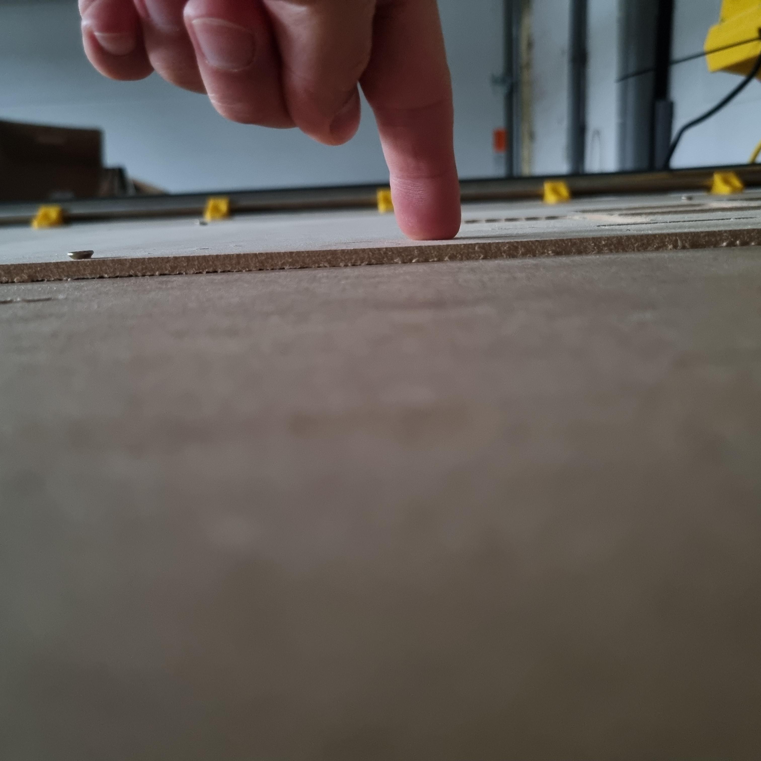
First I homed, moved to my starting point, did probing using g38.2 and g38.3 and moved up a bit to be able to remove the probe.
My stock is just a thin piece of mdf 4mm to test things. There seems to be a small gap between stock and the table. I would think a bad fixture would result in uneven heights but that is not the case. Measuring multiple sides give the same height.
That makes sense. That would mean it is cutting too deep into the material.
I’m not sure what the fixture is here. What is the depth of cut close to where you did the Z probe?
Have you surfaced the spoil board? That actually makes it parallel to the gantry (not necessarily flat). So if your 4mm wood was flat to the spoil board after your surfaced it, then the depth of cut would be consistent across the whole board. It still has to lay flat though.
This is a good idea. You’ll get a real feel for the error.
What is the design? Is it possible you can put a screw through the middle of the wood before cutting? Maybe in a hole you plan to cut out at the end? I sometimes make a separate CAM just to put pilot holes for hold down screws in the right place to hold the middle of the material.
So if you told your LowRider to move a certain distance— and measured and it moved something else other than that, usually off by a small amount, and it’s repeatable, and you determine that it’s because the E steps need adjusted, then there is a place inside the user interface for you to edit the E steps — and save to Eeprom.
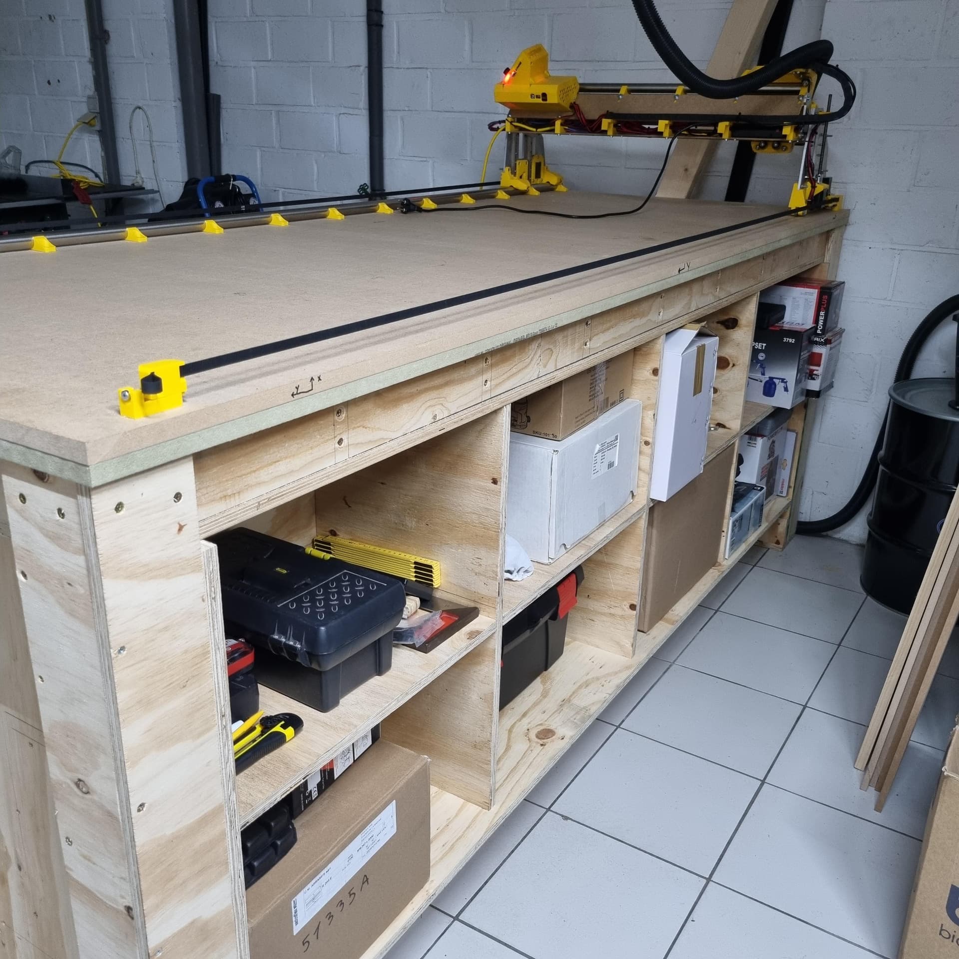
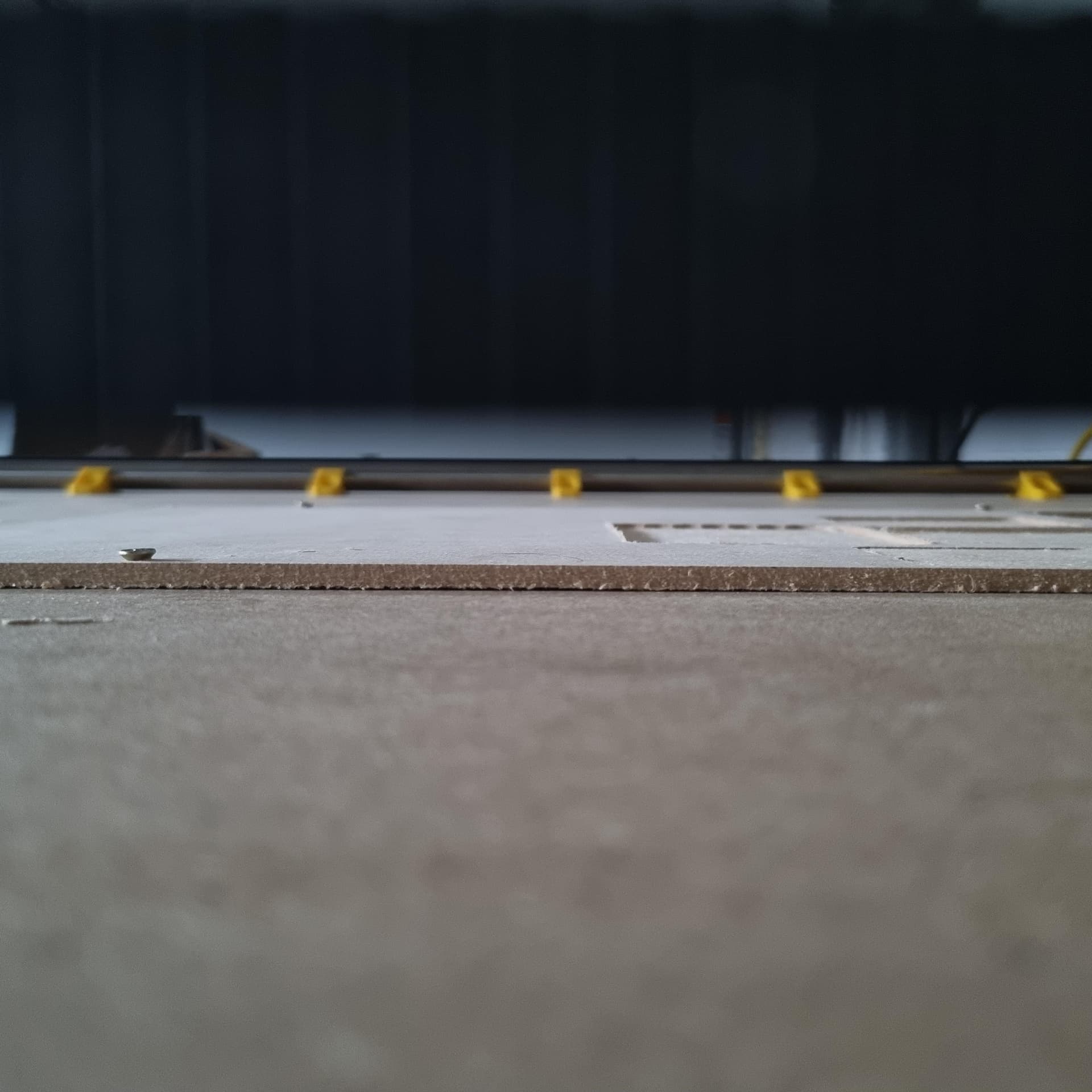
The bed is very flat. I build this table on a large flat construction space where they build industrial wood skeleton houses. The torsion outer walls are made with industrial laminated wood 100mm thick. I´ve measured <1mm between X0 and X640mm. Surfacing is on the to do list, but first have to drill many holes for the nuts to hold clamps.
The test piece I am cutting is super small so that <1mm tolerance should not be any dealbreaker?
Am going to double check tmrw! Will report back.
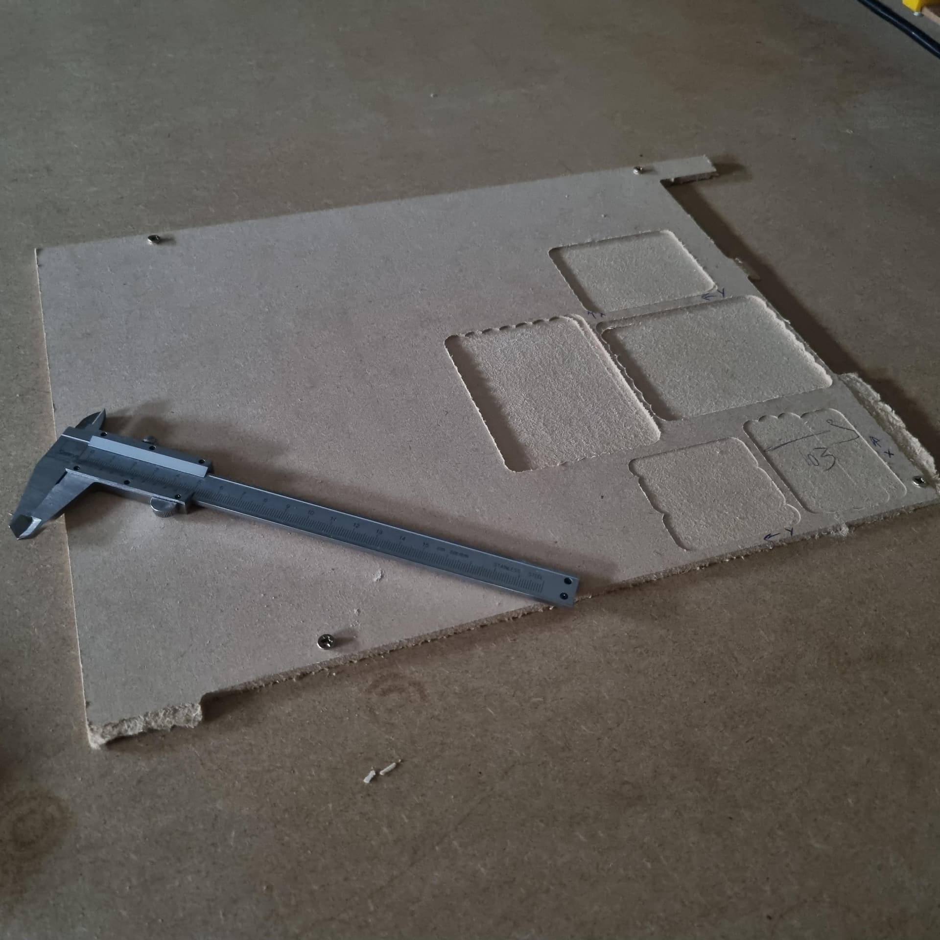
I have a small piece of 4mm MDF I am using, like 300x300mm. Screwed it down in 4 corners.
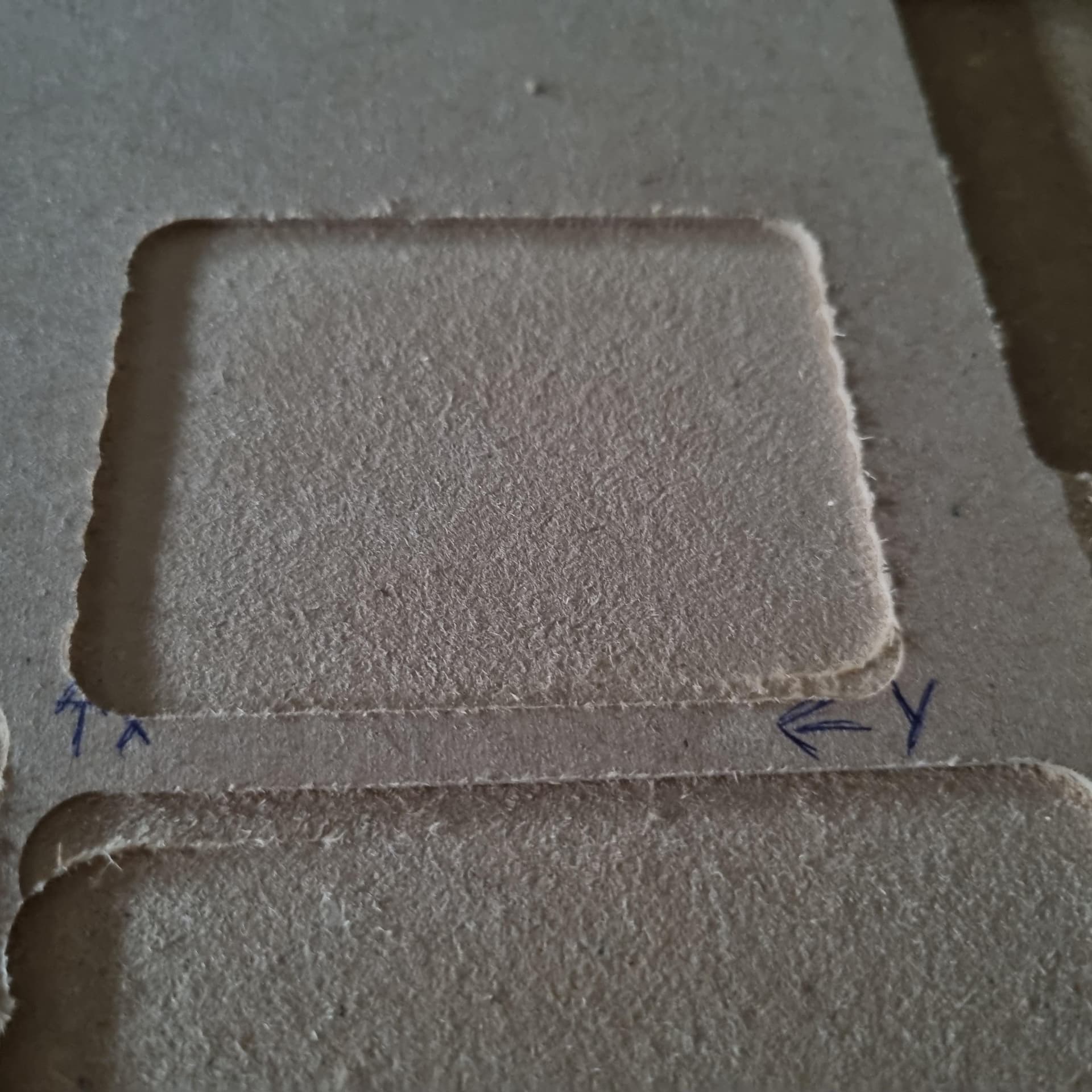
As I am using F360 and a dovetail, so I have a lead-in. Needed to measure few mm´s further away. That´s ± 1,9mm and on the otherside of the cut it is +1,7mm to be correct.
I can try for sure, it is just some scrap (is that the word?) I didn´t try that yet cause was scared to catch the screw. Will test and report back.
Thank you for learning me something new. Love you guys
Here it is!
;Fusion 360 CAM 2.0.16976
; Posts processor: MPCNC.cps
; Gcode generated: Thursday, August 17, 2023 5:10:27 PM GMT
; Document: Test Square Depth v2
; Setup: Setup2
;When using Fusion 360 for Personal Use, the feedrate of
;rapid moves is reduced to match the feedrate of cutting
;moves, which can increase machining time. Unrestricted rapid
;moves are available with a Fusion 360 Subscription.
;
; Ranges Table:
;   X: Min=2.436 Max=45.868 Size=43.431
;   Y: Min=-8.255 Max=56.343 Size=64.598
;   Z: Min=-1 Max=15 Size=16
;
; Tools Table:
;  T1 D=12.7 CR=0 TAPER=14deg - ZMIN=-1 - dovetail mill
;
; Feedrate and Scaling Properties:
;   Feed: Travel speed X/Y = 2500
;   Feed: Travel Speed Z = 300
;   Feed: Enforce Feedrate = true
;   Feed: Scale Feedrate = false
;   Feed: Max XY Cut Speed = 900
;   Feed: Max Z Cut Speed = 180
;   Feed: Max Toolpath Speed = 1000
;
; G1->G0 Mapping Properties:
;   Map: First G1 -> G0 Rapid = false
;   Map: G1s -> G0 Rapids = false
;   Map: SafeZ Mode = Retract : default = 15
;   Map: Allow Rapid Z = false
;
; *** START begin ***
;   Set Absolute Positioning
;   Units = mm
;   Disable stepper timeout
;   Set current position to 0,0,0
G90
G21
M84 S0
G92 X0 Y0 Z0
; COMMAND_TOOL_MEASURE
; Probe to Zero Z
;   Ask User to Attach the Z Probe
;   Do Probing
;   Set Z to probe thickness: Z14
;   Retract the tool to 40
;   Ask User to Remove the Z Probe
M0 Attach ZProbe
G38.3 F500 Z-180
G92 Z14
G0 Z40 F300
M400
M0 Detach ZProbe
; *** START end ***
;
; *** SECTION begin ***
;   X Min: 2.436 - X Max: 45.868
;   Y Min: -8.255 - Y Max: 56.343
;   Z Min: -1 - Z Max: 15
; Face3 - Milling - Tool: 1 -  dovetail mill
; COMMAND_START_SPINDLE
; COMMAND_SPINDLE_CLOCKWISE
; >>> Spindle Speed: Manual
M0 Turn ON 5000RPM
; COMMAND_COOLANT_ON
M117  Face3
; MOVEMENT_CUTTING
G1 X2.436 Y-8.255 Z15 F480
G1 Z5 F480
; MOVEMENT_PLUNGE
G1 Z0.27 F100
; MOVEMENT_LEAD_IN
G1 Y-8.251 Z0.17 F480
G1 Y-8.239 Z0.071 F480
G1 Y-8.22 Z-0.026 F480
G1 Y-8.193 Z-0.122 F480
G1 Y-8.158 Z-0.216 F480
G1 Y-8.117 Z-0.307 F480
G1 Y-8.068 Z-0.394 F480
G1 Y-8.012 Z-0.476 F480
G1 Y-7.951 Z-0.555 F480
G1 Y-7.883 Z-0.628 F480
G1 Y-7.81 Z-0.696 F480
G1 Y-7.731 Z-0.757 F480
G1 Y-7.649 Z-0.813 F480
G1 Y-7.562 Z-0.862 F480
G1 Y-7.471 Z-0.903 F480
G1 Y-7.377 Z-0.938 F480
G1 Y-7.281 Z-0.965 F480
G1 Y-7.184 Z-0.984 F480
G1 Y-7.085 Z-0.996 F480
G1 Y-6.985 Z-1 F480
G1 Y0 F480
; MOVEMENT_FINISH_CUTTING
G1 Y52 F480
; MOVEMENT_LINK_TRANSITION
G2 X11.123 I4.343 F480
; MOVEMENT_FINISH_CUTTING
G1 Y0 F480
; MOVEMENT_LINK_TRANSITION
G3 X19.809 I4.343 F480
; MOVEMENT_FINISH_CUTTING
G1 Y52 F480
; MOVEMENT_LINK_TRANSITION
G2 X28.495 I4.343 F480
; MOVEMENT_FINISH_CUTTING
G1 Y0 F480
; MOVEMENT_LINK_TRANSITION
G3 X37.181 I4.343 F480
; MOVEMENT_FINISH_CUTTING
G1 Y52 F480
; MOVEMENT_LINK_TRANSITION
G2 X45.868 I4.343 F480
; MOVEMENT_FINISH_CUTTING
G1 Y0 F480
; MOVEMENT_LEAD_OUT
G1 Y-0.1 Z-0.996 F480
G1 Y-0.199 Z-0.984 F480
G1 Y-0.296 Z-0.965 F480
G1 Y-0.392 Z-0.938 F480
G1 Y-0.486 Z-0.903 F480
G1 Y-0.577 Z-0.862 F480
G1 Y-0.664 Z-0.813 F480
G1 Y-0.746 Z-0.757 F480
G1 Y-0.825 Z-0.696 F480
G1 Y-0.898 Z-0.628 F480
G1 Y-0.966 Z-0.555 F480
G1 Y-1.027 Z-0.476 F480
G1 Y-1.083 Z-0.394 F480
G1 Y-1.132 Z-0.307 F480
G1 Y-1.173 Z-0.216 F480
G1 Y-1.208 Z-0.122 F480
G1 Y-1.235 Z-0.026 F480
G1 Y-1.254 Z0.071 F480
G1 Y-1.266 Z0.17 F480
G1 Y-1.27 Z0.27 F480
; MOVEMENT_CUTTING
G1 Z15 F480
; *** SECTION end ***
;
; *** STOP begin ***
M400
; COMMAND_COOLANT_OFF
G0 X0 Y0 F2500
; COMMAND_STOP_SPINDLE
M300 S300 P3000
M0 Turn OFF spindle
M117 Job end
; *** STOP end ***
Gcode looks fine (min Z is -1.0). Are you sure your touch plate is 14mm?
You should not need to adjust the esteps. The motors are often more accurate than our ability to measure them. And if a 10mm move is about 10mm then there is no way esteps are causing you 1.0 to 1.7 difference.
I agree. Adjusting e-steps would usually be for when you need 100 mm to be ~100 mm, not 100.6 mm or 101. Usually best measured over larger distances (like 500 or 1000 or more), knowing it will mean better accuracy on all your jobs.
ok, my kid finally gave up and went to sleep, so I could quickly test some things.
Conclusion no 1 is that I am getting older. My sight isn´t what it supposed to be. Going to buy digital calipers soon so I could read the .xy mm numbers again
The touchplate specs mentioned it was 14mm precise. My analog caliper says ~13.6-ish…
I think the conclusion is that, the combination of the small tolerance on the touchplate, combined with the small gap below the workpiece, might cause an error of ± 1mm in total.
Does that make sense?
Will do a test cut with an additional screw, and modified touchplate height. Will report back afterwards
Yes sorry, have been using this since few years, didn’t think about that.
Anyways, new test cut gives 1,1mm ± so that is close! Will measure the touchplate with a better caliper to get even closer. And ofcourse will tighten flexible workpieces some more.
For flexible workpieces, you can also lay out long flat boards on top of it on either side, and clamp those boards rather than the workpiece itself
This will distribute the pressure a little bit better…
Of course, depending on the cut you’re trying to achieve, and the size of the stock, this might be impossible, but it’s something to keep in mind for workholding…
Also, it’s worth noting that side clamps have the same tendency to lift the stock, so if that’s something you use, you have to be careful about this
Finally, holding those thin sheets , if that’s something you do on a regular bassi , is best done with a vacuum table (but tt’s a whole other story…), or calls for some kind of pressure plate or rollers