I have a bass guitar neck I’ve designed in fusion 360.
I would like to mill the front side in 2d mode so that I can select tools to do certain operations (ie V bit for logo, 1/8" bit for truss rod slot, 1/4" bit to cut out the body and to mill the head stock flat).
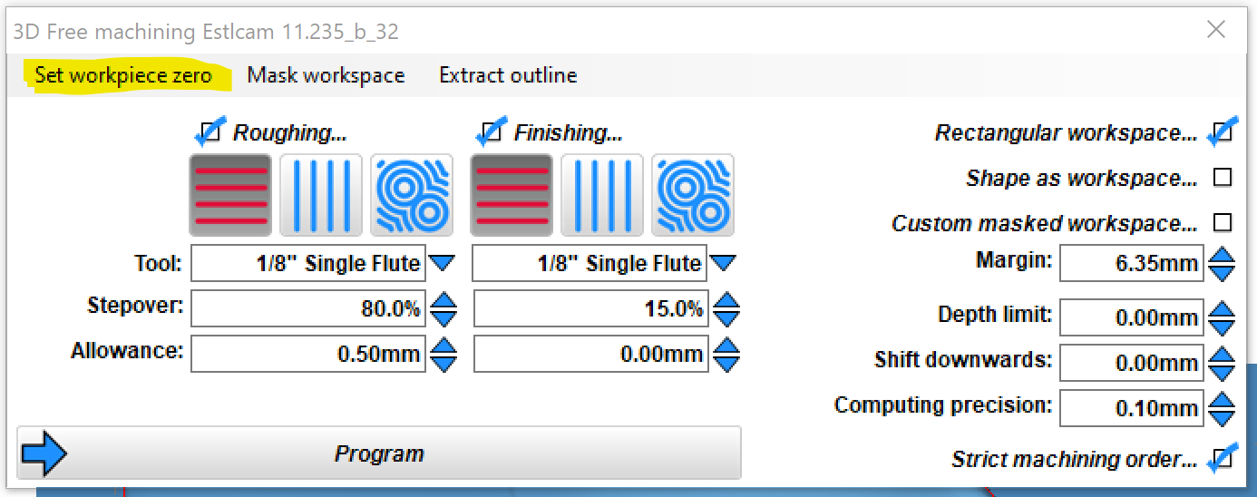
I would like to mill the back side in 3d mode so that I can carve back of the neck.
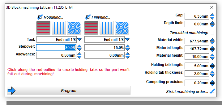
So my process (I think) will be to save the sketch of the front side as dxf and open with Estlcam in 2d mode. And also save the whole thing as stl and open for block machining in 3D mode.
I will then use the gcode generated by the 2d sketch and the second (of two) gcode files generated in 3d mode (the second file is the back side of the object).
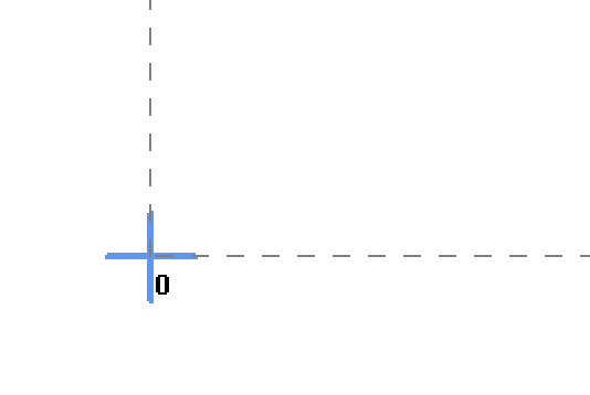
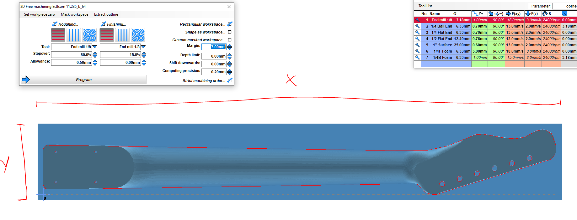
My question is where the Zero point defined by Estlcam is, since I will have to flip the material over. Is the zero spot defined exactly the same between the two modes?
Hi, thanks! I know where to change the zero spot in each version, my question is really how it’s generated in 2d and 3d in each version of the software.
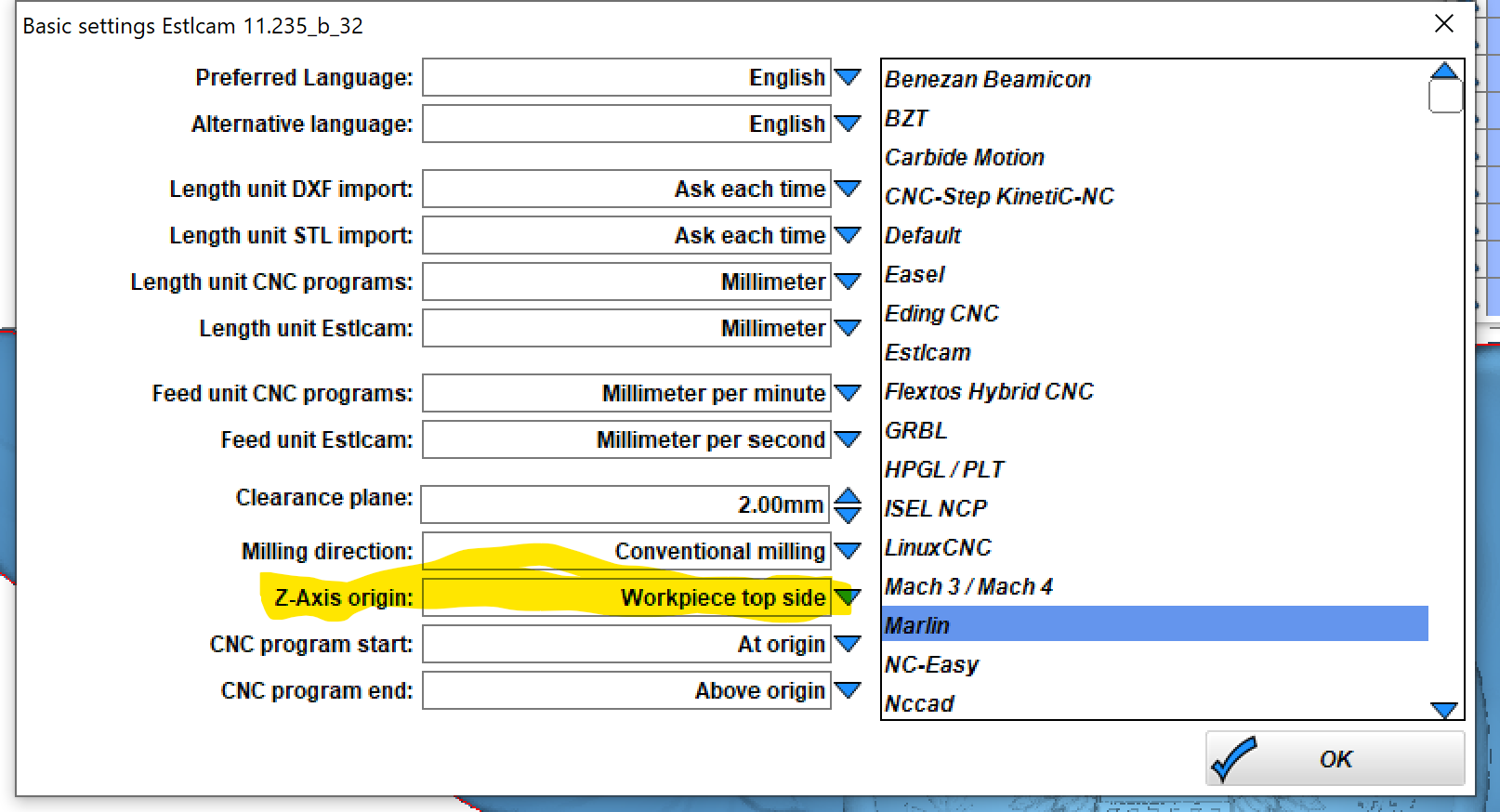
Btw: the z-axis origin (second picture) is a whole different problem. Lol.