Hello! I’ve been building a zenxy v2 with my kids over spring break and we are so close and have had a blast putting it all together, but we can’t seem to home…
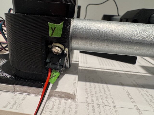
The optical sensors from the V1 store have 3 wires and the GPIO pins have 2… Also the connectors the optical sensors come with are too fat to connect them next to each other to get to the right GPIO pins.
I’ve not been able to get the sensors to trigger. I’ve tried putting the connectors into the GPIO slots in every combination and even though the green LED goes on, I’m not getting any NegLimitPins triggers.
I’m worried I may have burned out the sensors when I tried a few arrangements! Is there any way I can easily test to see if the “light” is still working in the sensor? I’ve tried with my front facing iPhone camera, but that doesn’t seem to work (which also leads me to believe I may have blown something). I just can’t tell if it’s my wiring or if the sensors aren’t working.
Any thoughts?
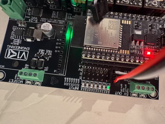
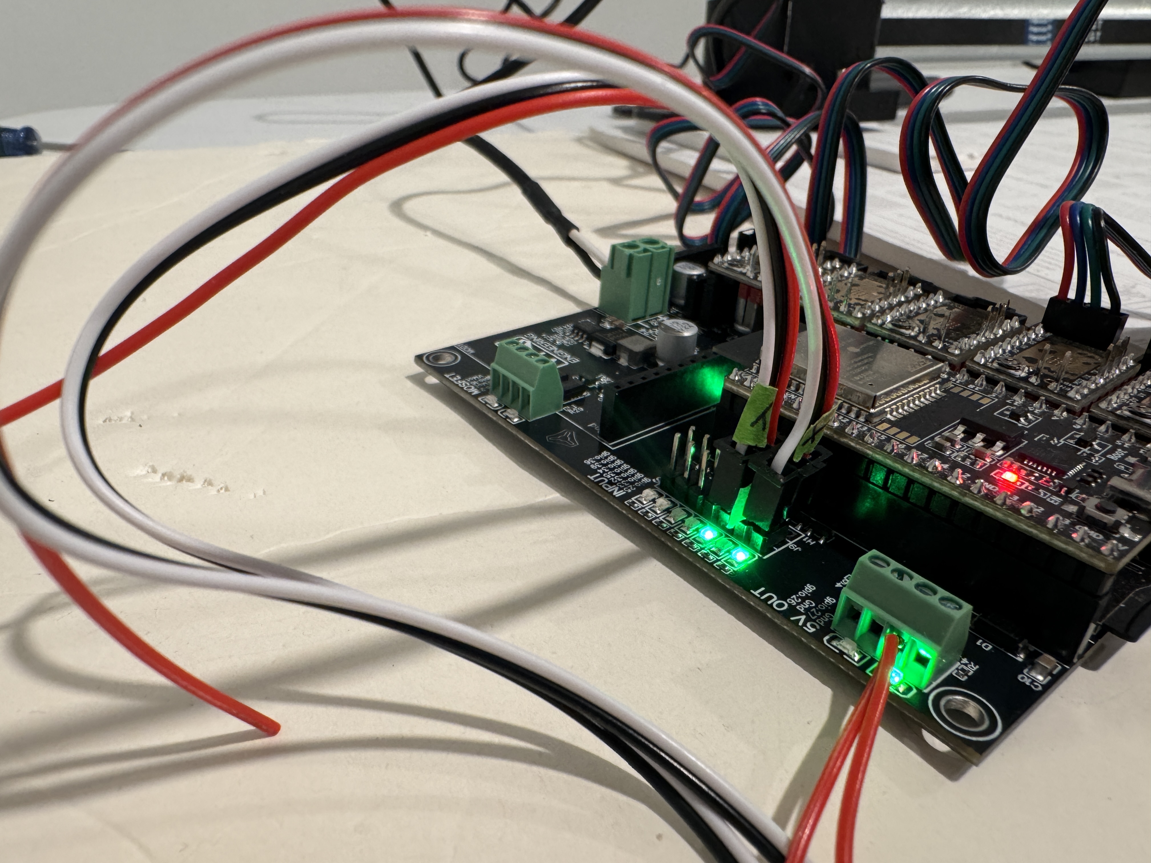
you can see in the pic below I have red and black connected. When I have white and black connected I still don’t get anything when I run $limits and then break the sensor…
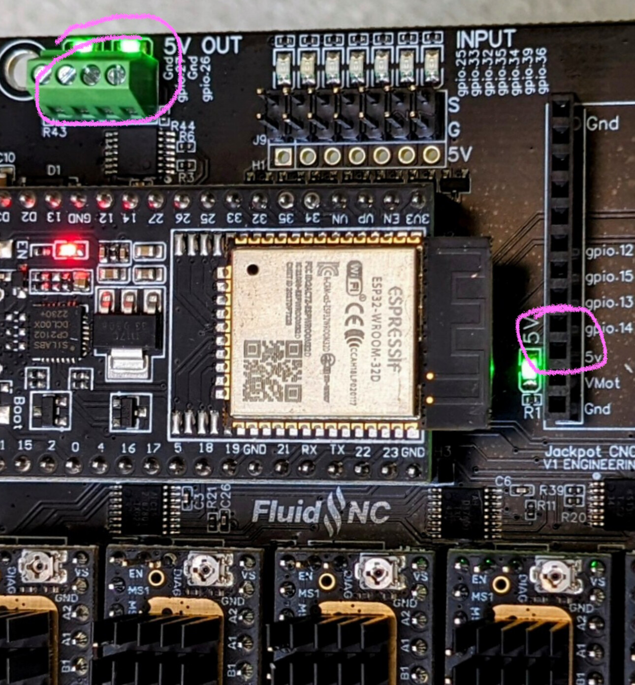
The optical sensors need +5V (3.3V will do, however.)
There is an empty pin header along with the signal and ground pins. You could solder those in, or splice something to the optical stops from a 5V rail.
If I recall correctly, red goes to +5V, black to ground (middle) and white to the trigger pin, so yours aren’t plugged in correctly.
Totally new at any sort of electronics so I appreciate your gentle response. I want to learn.
Are you saying I don’t have power going to the optical sensor? If that’s the case why does the green led on the board go on? (Totally noob q, please be nice.)
I don’t have any soldering skills…. This is a grade school project. Is there an extra pin I can get the 5v from?
I keep any initialization gcode in a file on the SD card and run at startup:
startup_line0: $SD/Run=init.gcode
Not sure, but you might also be able to just update the pin definition to force it on by default by adding “:high” to the end of the pin definition: gpio.27:high