It’s been a REALLY long time since I’ve posted anything, life seems to get in the way, so I wanted to show you all something I’ve had on the back burner for the past year and finally slapped together.
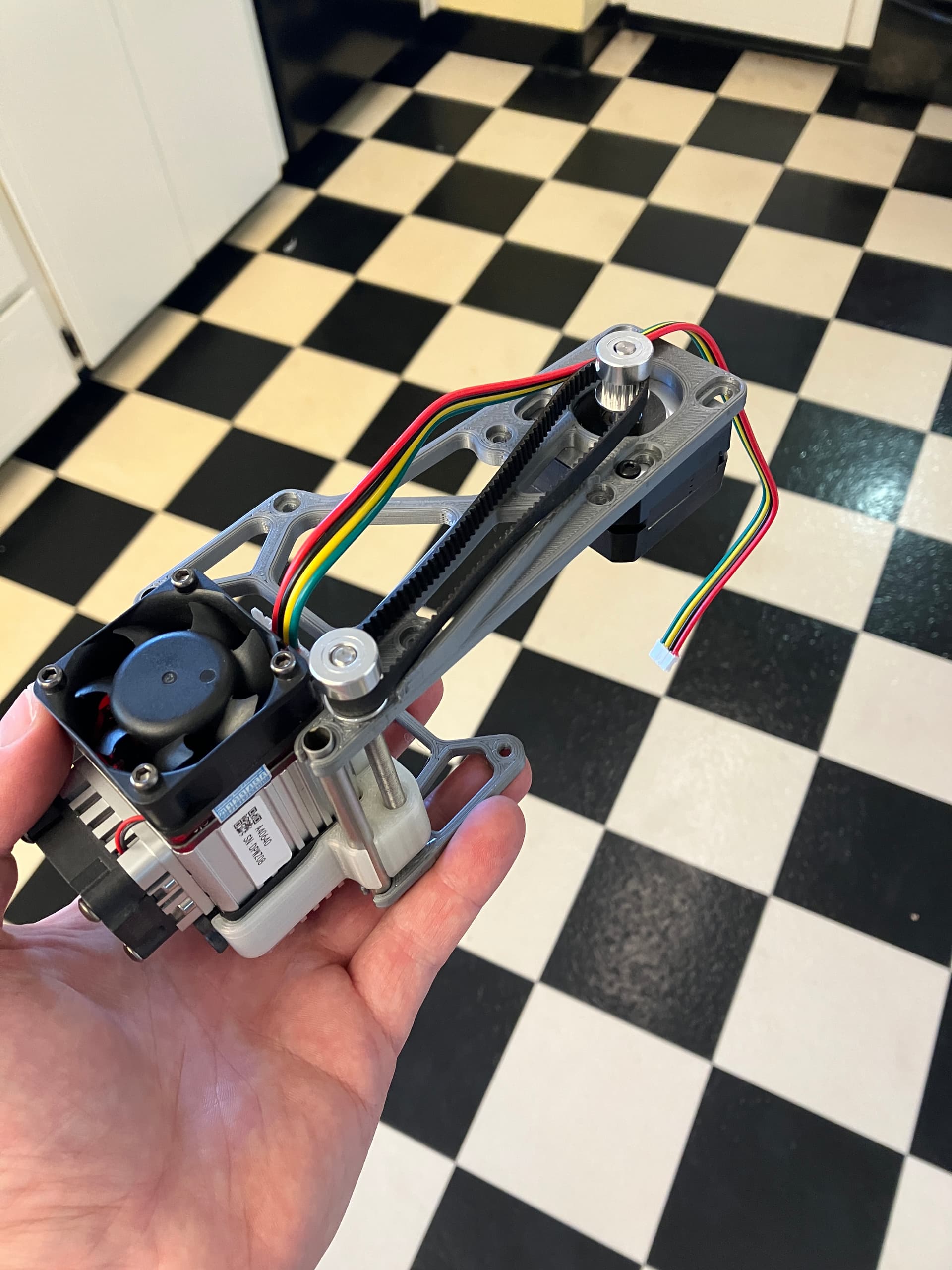
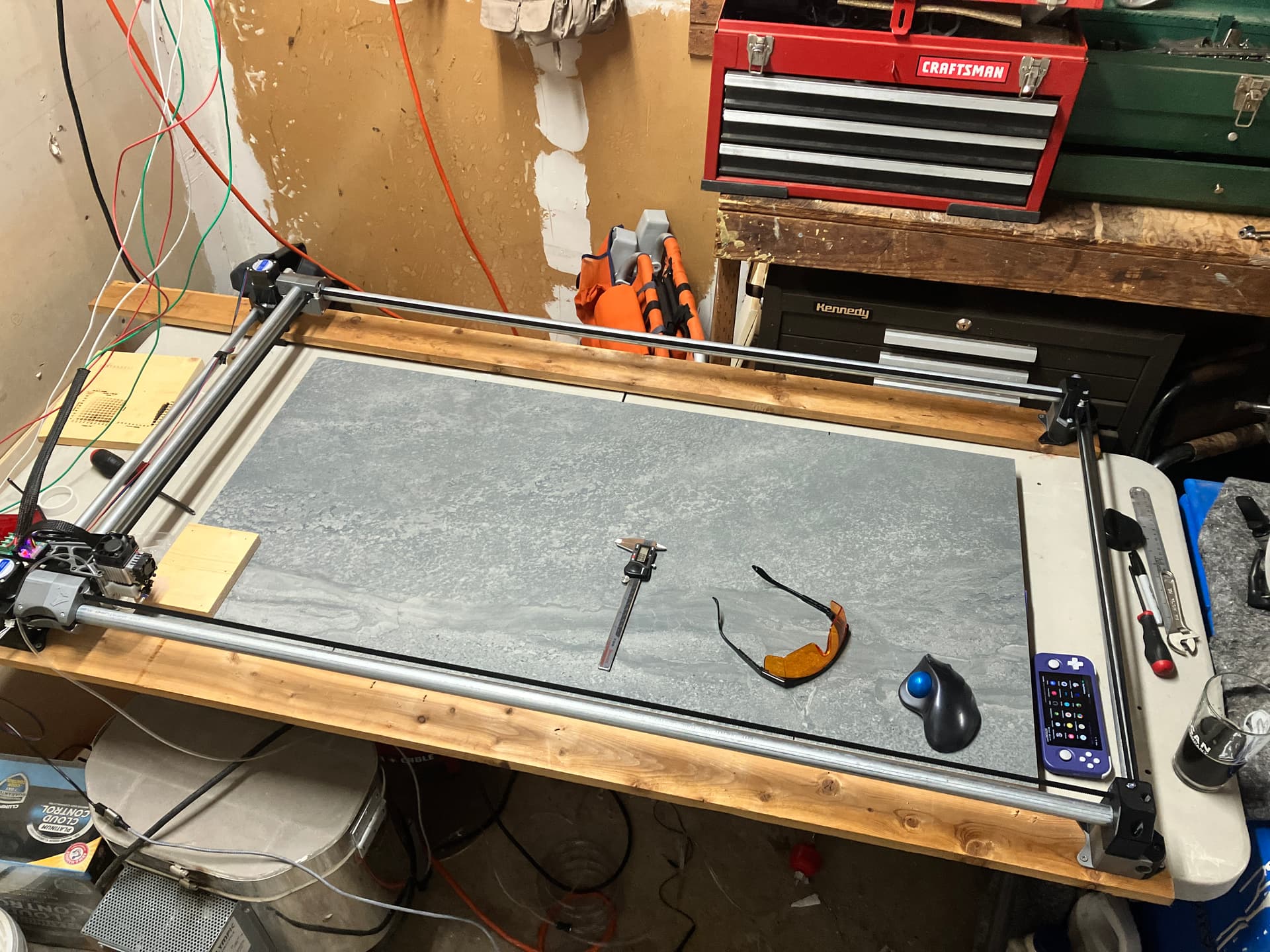
Behold, a way to large ZenXY that I tainted with my own ill thought idea for a Laser mount.
That looks really neat. There was talk of a light weight laser version of the zxy.
How do you get wires to the middle? That has always stopped any plans I have to do this.
What about making a much larger pulley on the Z axis leadscrew side? If you went a tad higher, you could fit it. The motor could move a little closer too. You might some top speed.
The wiring is something I still haven’t designed a solution for, the plan is to use the measuring tape with expanding tube method as that has worked well on other machines I’ve put together.
I’m not sure what a larger pulley on the z axis would achieve, could you elaborate?
I chose to mount the z axis motor off the backend to limit deflection of the x axis tubes as they are not torsionally constrained and to lower the COG to reduce movement during rapids.
Ah, the issue with stiction is not that the motor isn’t powerful enough to move the carriage, its that the carrier printed in nylon does not slide well enough on the metal tubing which can lead to stuttering or getting out of alignment.
its one of the pitfalls of the off center lead screw, but that was a compromise I chose to make the assembly more compact. There are multiple things that could be improved beyond better linear bearing surfaces such as having a rail/tube with a better surface finish and/or centering the lead screw behind the carrier.
I gambled on the offset lead screw as I’ve seen in work in other systems, most notably ender 3 style printers, but those rely on 3 roller bearings per rail to constrain the assembly that don’t have the same stiction issues as what I’ve designed.
In the end the goal was cheap/compact/lightweight but I may have over simplified my approach.