Hi all! I’ll start with a bit of background, then go into what I did wrong, and my troubleshooting steps.
The seeds of my fascination with hobby CNC started many years ago (2012) when I found an instructable detailing a small hobby CNC router build. It used acrylic sheets, steel pipe, and some flimsy aluminum edging (j-channel maybe?). I definitely bought an over-sized set of stepper motors for that thing (NEMA-23 !) and quickly became frustrated for a few reasons:
- it needed a desktop PC with a parallel port
- the motors weighed far too much
- my skills with tools to actually put the thing together were pretty poor (I’m better now)
- things cost more in Canada

- I had a lack of space to put the thing together
- the only source of documentation was the instructable, and my internet searching skills were not good enough to find more.
Due to these reasons I eventually shelved the whole thing. I bit off a bit more than I could chew for sure, and made more mistakes than successes.
Fast forward to 2023 and I found the V1 engineering website (don’t remember how). I had purchased a 3d printer in 2019 and my excitement grew! I could do this! I put a list together for parts and started printing - it took a few weeks after work and on weekends to finish all the prints but they came out marvelously on my prusa i3 mk3s, and actually after the last one finished my printer jammed worse than it ever has and I didn’t touch it for 8 months. Work and life got in the way too, and I picked this project back up a month ago again.
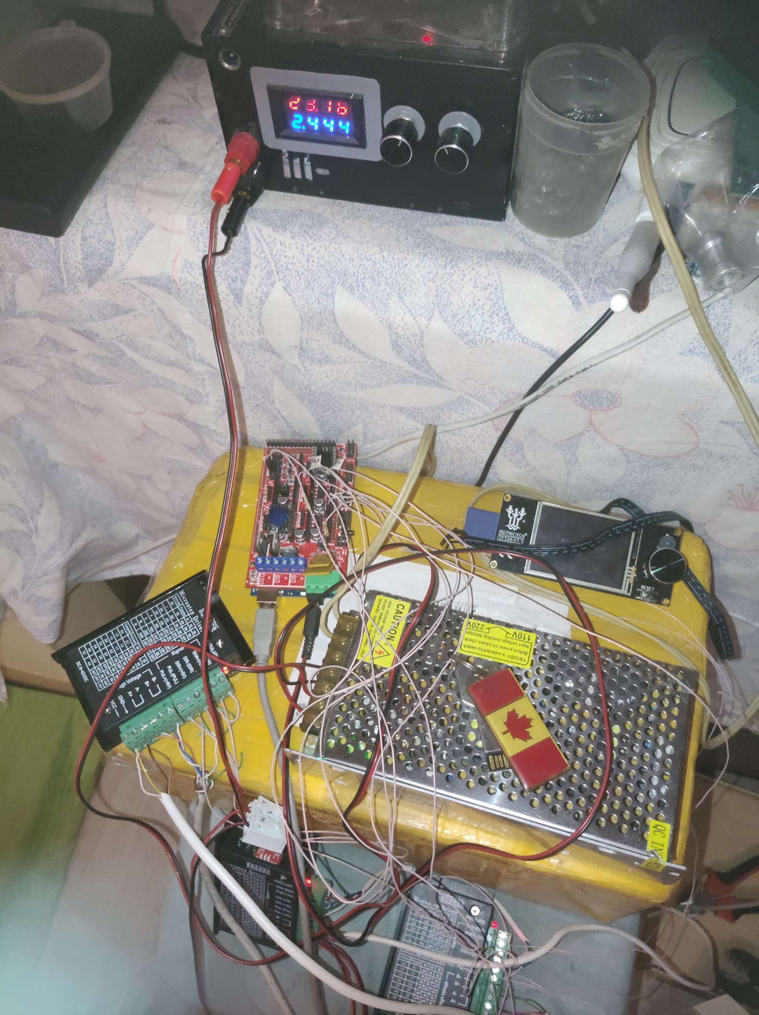
I decided to go with the SKR pro v1.2 bundle from the V1 store. I had a power supply laying around so didn’t buy one. I made it almost all the way through the instructions and was going to test out the controller board. I wired up everything, double checked the wiring, and plugged in the power supply. ZAP! HISS! SIZZLE! the blue smoke was released. I looked up, unplugged the supply, and quickly realized…
*** it was the 36 VOLT SUPPLY AND NOT THE 24V supply! Oh no! Could I save the board? ***
Here’s what I noticed:
- The schematic was available on the bigtreetech github page (step 1 complete)
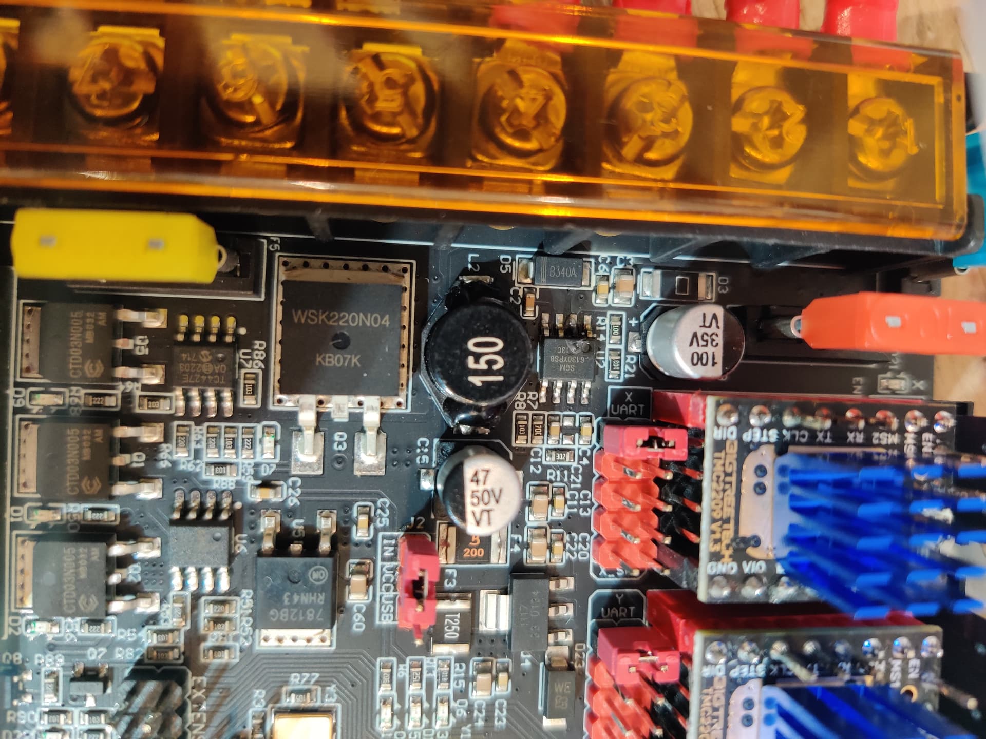
- I saw that the input DC to DC chip (SGM6130) input pin was where the smoke came from, it was black and obviously the chip was fried. When I input 36V DC into this chip, it blew because it has an absolute maximum input voltage of 31V (see datasheet)
My next few questions were:
- Did the damage extend beyond that chip? Because if not - I could potentially replace it with my own sub-circuit (I have some electronics skills).
- Did the 7812 voltage regulator also get fried? It is more forgiving and has an input rating of 35V.
- Did the motor-drivers (TMC2209) all get fried? Because I had jumpered the input voltage to the motor input voltage as well… and the datasheet for those chips says absolute maximum of 33V!
I took the SGM6130 chip off the board, and did some probing and testing
- The two fuses on board were fine (kind of expected, the voltage was high, not the current)
- I input 5V on the USB bus after swapping the jumper on board to use 5V from the USB instead of the SGM DC DC converter chip. The green LED for the 5V supply turned on and the TFT screen gets power - but now the TFT screen board had something SIZZLING and smoking on it!!! UHOH! (Turns out this was likely the LEDs on the front of the board, and the screen functionality is all there otherwise from what I can tell).
- I probed (while power off) the 3.3V rail, checking continuity to ground… it was too low for confidence… it was like 1.5 Ohms or something like that, and the fuse on the 3.3V rail is 750 mA (F3) so I didn’t bother trying to input a 24V supply after finding this, or injecting my own 3.3V.
- I Removed the 3.3V regulator as I had nothing to lose if that was the faulty component on the 3.3V line (it wasn’t). I chcked D23 (which is a TVS diode supposed to suppress voltage transients) but unfortunately, it did not suppress the 36V that I mistakenly put in… Oh well.
- I removed some other components that I would not need on the 3.3v rail, like Q7, Q10 … but none of them were faulty.
At this point, my skills are nearly exhausted for debugging the board. If it’s the Atmel chip itself that is fried then It’s not really worth my time trying to remove it and source another one. So, I bought another SKR pro board.
It arrived last week, I was much more careful this time, and it turns out my old motor drivers are fine, and so is the TFT screen.
Today, I got first movement ![]()
Thanks Ryan and all who are a part of this community. I hope someone learns from my mistake, double check your input voltage!