Hi everybody, I have a MPCNC 500x500 with a ramps 1.4 and with the preconfigurated firmware MPCNC511_GLCD and with the end stop for X and Y axes. I use MPCNC with a modest laser module (chinese) and I engrave paper or wood or acrylic.
I would like build a panel in acrylic with some written e with some holes for the switches. For this I will engrave the written with the laser and I would like cut the acrylic with a router (I think with a dremel).
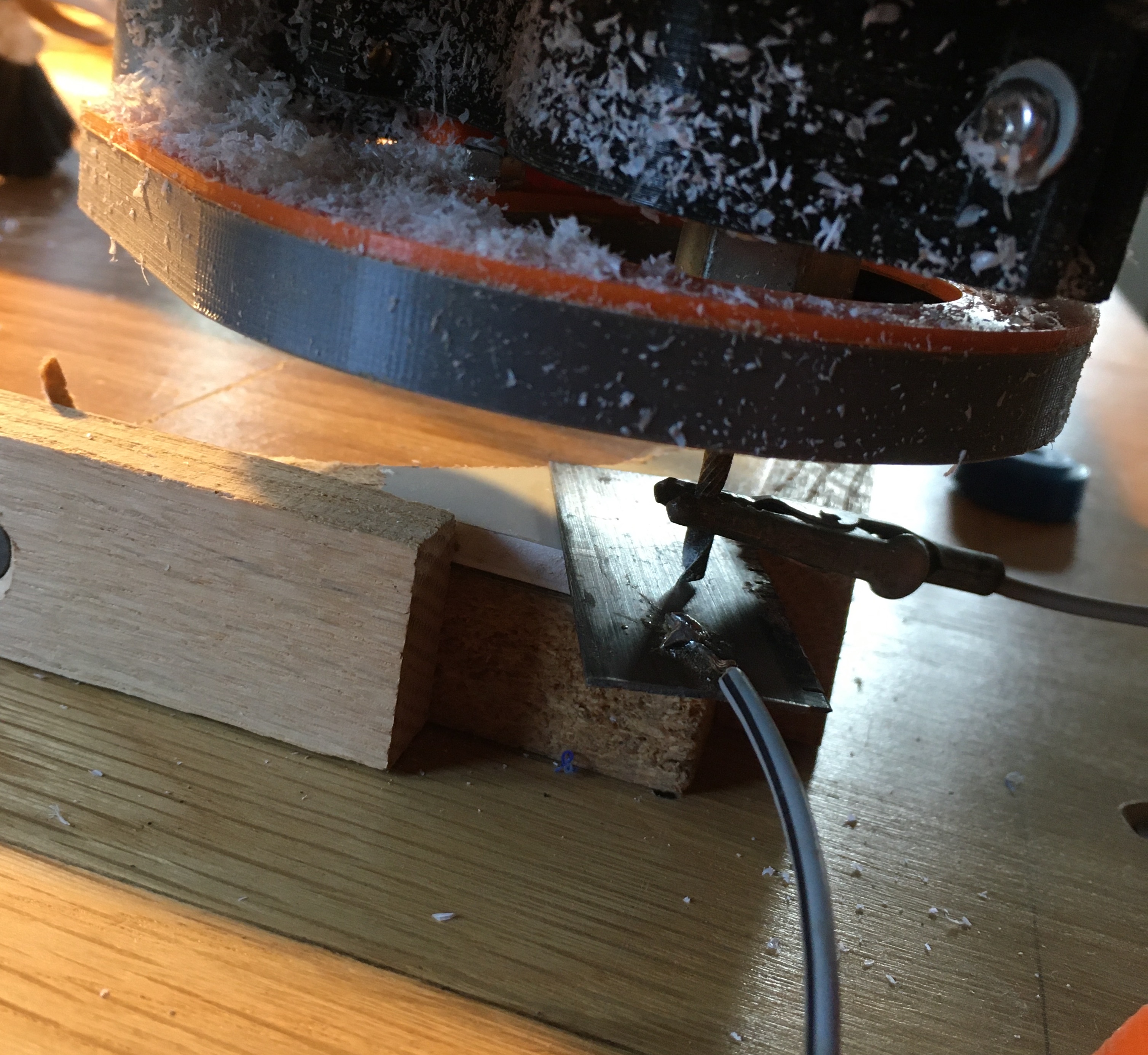
For this I must set the Z zero and I would like use a “touch probe” ( I was Inspired from this VIDEO) but I haven’t idea how build it, can you help me for make it and for adjust the firmware?
It is as easy as a wire from the Z min endstop signal and ground. One to the tool, one too a thin piece of metal. You can adjust for the thickness in the firmware or gcodes.
Hi Ryan,
In your reply to Pietro above, you said:
It is as easy as a wire from the Z min endstop signal and ground. One to the tool, one too a thin piece of metal. You can adjust for the thickness in the firmware or gcodes.
Pietro managed to follow your logic, but I’m confused.
OK - so we have two wires. One attaches to the Z min endstop signal pin and the other to the Z min ground pin.
Now, which wire attaches to what? Does the ground wire attach to the router bit? And the other to the metal edge block?
I’m guessing here, but this seems a reasonable guess.
It doesn’t matter, or at least it shouldn’t. The firmware is looking for the signal pin to be connected to ground. When they are touching, it is connected. When they aren’t touching, they are not connected.
Depends on the router and wiring signal to metal ground to cutter is safer. My router and arduino have a common ground so if I connect the signal to the bit it thinks it is zero and it is not
My touch plate is working as expected when I do a Home Z from the display, tests completed last night. I am happy.
I have a question that I think I saw the answer way back (and I don’t mean Rocky’s Way Back Machine)
but after the homing is complete and you remove the touch pad and clip from the bit, when a job is cutting, what happens if the clip and touch plate touch? I think I read somewhere that it is ignored. Is that correct?
I want to make sure so I know any precautions that need to be taken after finishing the Z homing.
The pin is ignored during cutting. I cannot think of any reason that Marlin would even read the pin outsize of Z-probing. You can verify for yourself that it is ignored during cutting by running a job without the router running above your cutting surface and then manually (clip not connected to the bit) touch the clip to the probe plate. And touching the two just pulls a pin to ground, so I cannot think of any reason that it is not safe to have them touching for extended periods of time.