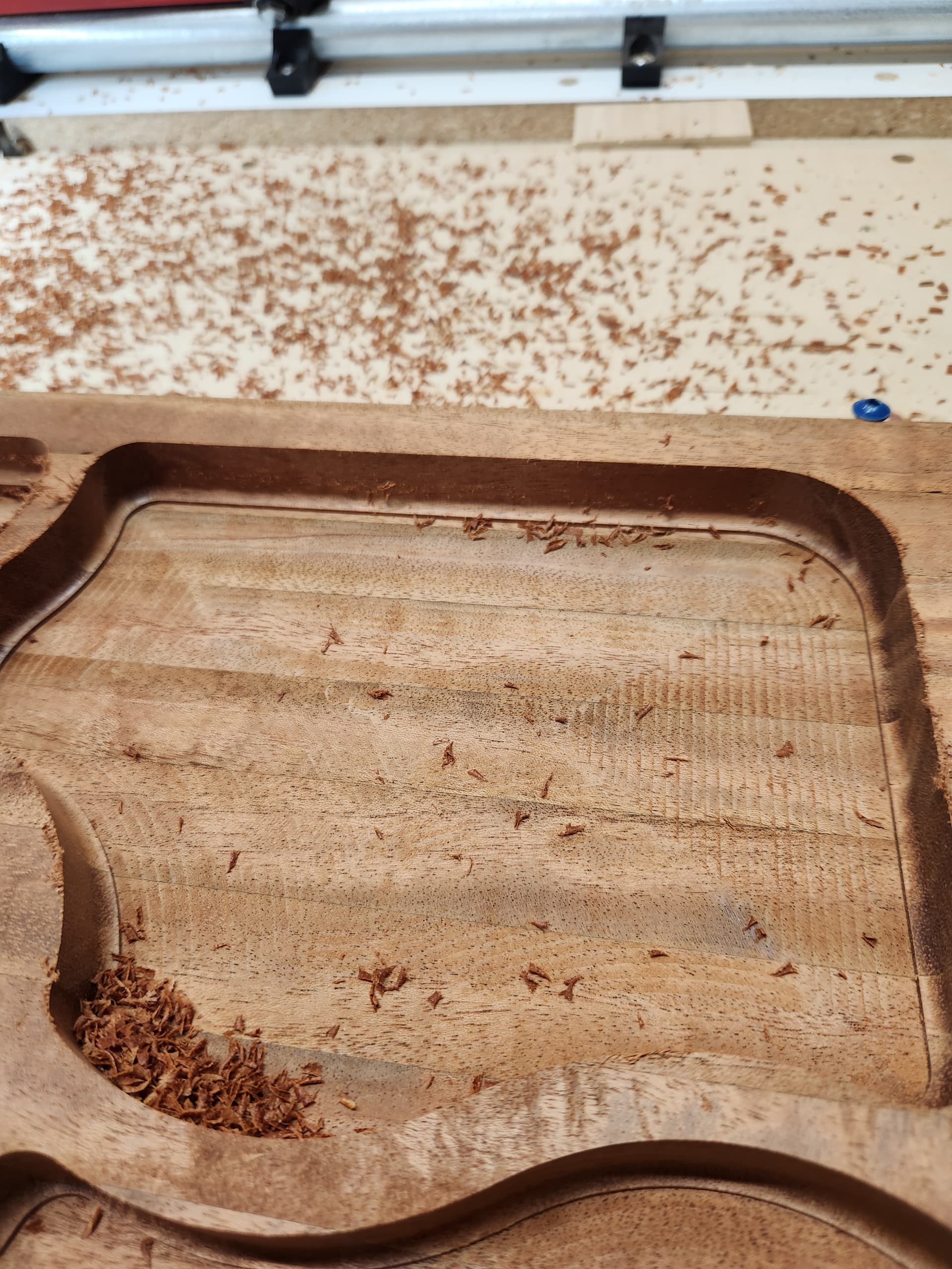
Any tricks to matching z height on tool changes. The is a particularly bad example. This is a 1/4 end mill to clear the pocket and then a 1/4 ball nose to round the bottom. There is a 3mm overlap of the ball nose. The depths are off by about 0.5mm and I ran the ball nose twice to make sure I did not miss probe after the tool change. I am using the probe plate from the v1 store.
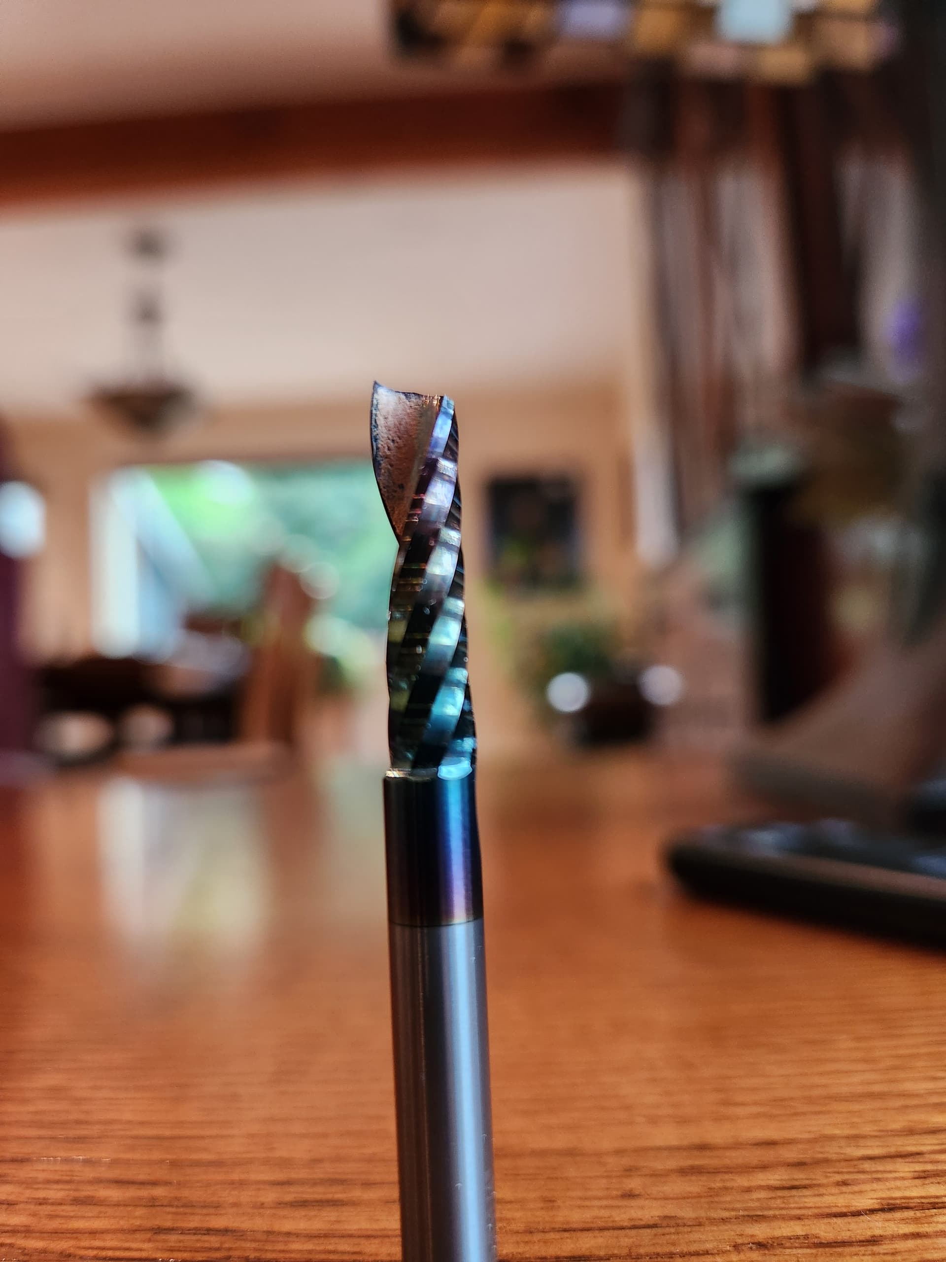
I think I figured this one out, but I am still interested in other peoples methods of getting the same height between tools. The tiny touchplate seems a little inconsistent for me and usually requires sanding. I am sure there is a technique to it that I have not mastered. In this case, I just switched to this single flute O bit and I probed on the corner of the material. I did not realize the tip of the bit was sloped, so I think I didn’t probe on the lowest point, so the clearing bit went deeper by 1.2mm.
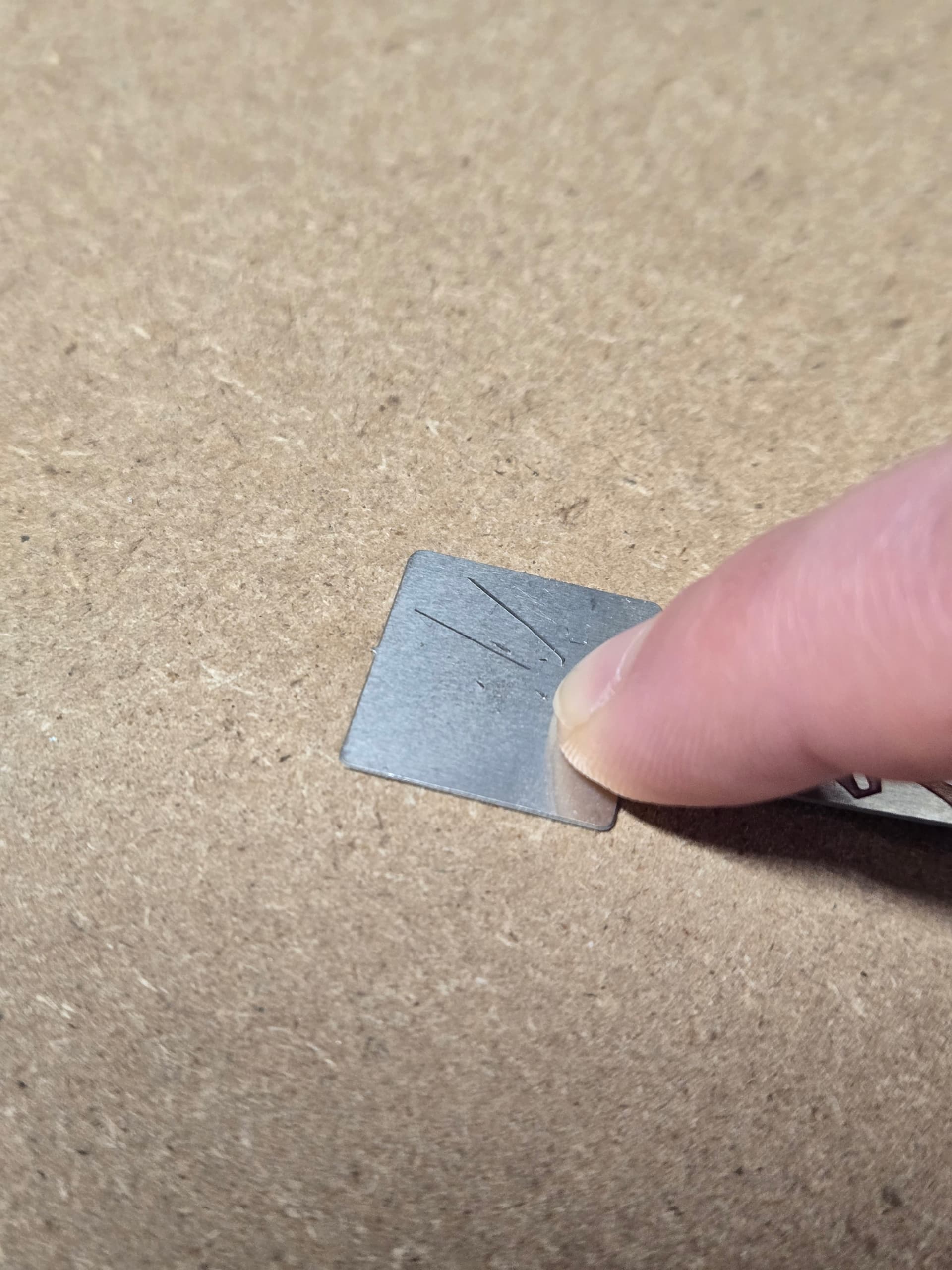
There will be a small inconsistency with using about any touchplate, unless you neurotically clean the surface that ypunput the touchplate on. A chip or speck of sawdust will affect the touchplate.
Also there are limits to the ability of the controller to react, so super slow probing is needed to get really consistent results. There nay be different factors from bit material as well, but that just cant be helped.
If you use the V1 bits, they come with a retaining collar. That collar will, when placed hard against the collet put the cutting edge at a consistent height, though of course relative to where the collet nut surface is. This works great for tool changers.
For me, I find the tiny touch plate accurate enough, if I use a tack cloth to clean the probed surface each time.
1 Like
A manual bitsetter with some lock collars like this: link
You dont need to buy it. There are other ways to get this and get the same results.
1 Like
You’ve been recommending this method for awhile. I might try it. I’ve got a project I’m working on that needs 3 or 4 tools and that’s a bit of a pain.
I see you can buy the model for the bitsetter to 3d print it yourself for $2 instead of $20 if you need both 1/8 and 1/4 inch. Although, you would need to source the metal disc.
1 Like
Some of this is based on fact and some of this is based on feeling. I might also be a bit detail obsessed (aka crazy).
First, what board are you using and how are you probing? My experience is with FluidNC and there are some slight differences. You can probe via a probe panel in the WebUI, probe commands in the gcode itself (as defined on milling basics), or just running a probe command directly or via a macro. If you’re mixing these or zeroing Z manually after running the G38.2 probe command, you could run into issues. You should not run a G92 or G10 command to zero Z manually (which the default commands for the WebUI probe panel will do). This is automatically done by the G38.2 command based on the P touchplate thickness.
From the FluidNC wiki: Probe | Wiki.js
After the probe touch, the status will show the axis location to be a little off from the probe location. This is due to the deceleration after the probe touch. The probe location is accurate to the actual touch point. If you want to minimize the over travel use a lower speed (best) or faster acceleration (in your config file).
So, that means once the probe is triggered, it actually moves a little bit past the trigger point due to deceleration. In my testing, if you manually zero Z after probing, it was about 0.4 mm lower than it should be.
Second, how are you using the tiny touchplate? Are you using the clip to attach to the bit directly? Are you using the magnet to attach to the bit? collet nut? Since the bit has the tiniest tip that actually makes contact, I think it matters. That 1/4 inch ball nose has a bigger surface contacting the touchplate so I would expect it to be more forgiving. I usually clip directly to the bit because I feel that makes the best connection. Sometimes I’ll put the magnet on the bit but I don’t trust the magnet to the collet nut for this type of bit. I don’t know if that is based on fact or just feeling.

Also, in terms of actually using the touchplate, I think most will hold the touchplate on the skinnier part and bend it flat to the surface. If you aren’t getting the full square flat to the surface, it may not be accurate.
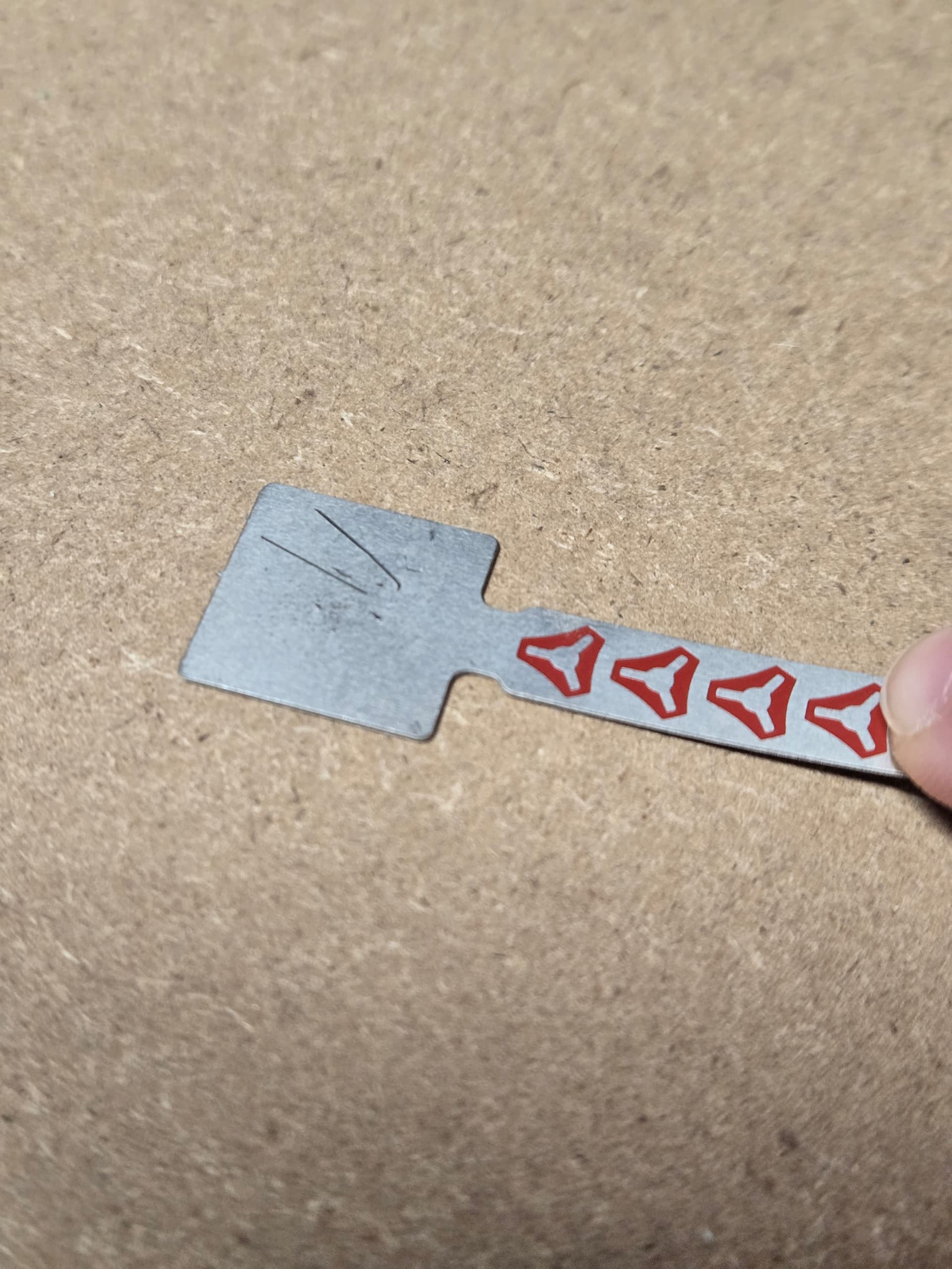
What I do, to make sure it’s flat against the work surface is actually push down on the square part. If the workpiece isn’t fully secure to the spoilboard, this would make a difference as well. I went into a bit of a probing accuracy deep dive when working on some Z leveling gcode. That probes a location 3 times and averages them together. I can pretty easily get sub 0.1 mm repeatability when doing this and clipping directly to the bit.
Third, and again because that bit makes the tiniest bit of contact, you could try doing a double probe. For FluidNC, the gcode is generally this (from the milling basics start code):
M0 (MSG Attach probe)
G38.2 Z-110 F200 P0.5 (probe down set thickness )
G1 Z10 F900
M0 (MSG Remove probe)
It might be that the 200 mm/min is too fast for that tiny tip. So, you could add moving up a bit and re-probing at a slower speed.
Something like this:
M0 (MSG Attach probe)
G38.2 Z-110 F200 P0.5 (probe down set thickness )
G1 Z5 F900
G38.2 Z-10 F80 P0.5 (probe down set thickness - slower)
G1 Z10 F900
M0 (MSG Remove probe)
And lastly, note that the milling basics tool change gcode probes at X0 Y10 (G0 X0 Y10 F2520). That has bit me before. You need to make sure that there is ample material left to probe at that position. If you’re not getting the full touchplate square to touch at that position, you may run into issues.
I do something real close to this and it has worked real well for me. I don’t come up quite as far on the second probe and I come down at F20 so you can barely see it move but its worked real well. Was originally @Michael_Melancon idea and I stole it ![]()
1 Like
Yea, I just made up numbers but I bet moving up 2 mm (or maybe even less) and using a 20 mm/min probe would be about as accurate as you can get. 2mm at that feedrate would take 6 seconds.
1 Like
I think I come up 3mm. And after that I come up 30mm so I can easily put the dust shoe on ![]()
You can just do this with a piece of wood, some aluminum and 4 screws, what you would need is some collars, the same geight both 1/4" and 1/8"
My acm vbits and my 1/8" spiral bits are the same height, so i use this method. Given this is for working on the same sheet i measure the z only once and perform both gcodes. Never had any issues