I got some issues that I cant figure out at the moment.
Just completed the build and trying to figure things out. However my Z2 endstop is up to something wierd. It doesnt always trigger, resulting in Z2 stepper trying to go further then expected.
I got the SKR Pro board.
Its connected C - NC
The red diod lights up when triggered.
I have messured for continuity (all good).
I have tested with M199 and sometimes it trigger, sometimes its not.
I have tried triggered it at different locations but I cant find a pattern on when it triggers.
I have soldered both ends.
When unplugged from board M199 says triggered. When connected open/triggered.
Got working dual endstops for Y
Did you bend/clip the diag pins on the TMC2209 drivers? If you don’t then the SKR board ignores the actual stop switches and only obeys the sensorless homing. It’s a known flaw.
Some of the SKR boards are out of whack with the LED indicators, and though the LED lights, the pin doesn’t actually trigger. An additional pullup resistor between the signal pin and the +5V pin can help that, or desoldering the LED lamps.
It could be a melted switch, but you may also have to…
Dan was referring to a known design flaw with the SKR pro limit circuit. It was designed by someone with little experience:
If you know electronic theory you’ll spot the issue. Otherwise, you can take our word for it that it will be much more reliable after the LED(s) are removed. If it were me, I’d do it an every SKR pro board I use.
Truglodite, Kev:
I’m not that confident in my abilitys regarding electronic theory. I’ll keep this ín my mind thou, thanks!
Robert,
I am pretty sure they arent reversed. Since the gcode commande indicates correct endstop ID is triggered when I test them. But I will check again today.
I have ordered a new endstop, just hope it arrives tomorrow
This may be nothing pertinent to your situation, but in one situation sounding similar to this I found that there was actually a wiring connection in the middle! And it was the problem.
Alright. I have replaced the endstop-switch and made a new JST connector. Still same problem. It works as intended sometimes, and next time I home to Z2 wants to climb to the roof…
They are not reversed. Cable seems fine (only checked continuity while moving it).
I get the feeling its board-related. Any other suggestions before I will look into remove the LED for Z2 endstop?
It seems to be working now after doing as suggested by removing the diode. Atleast it hasnt occured since I “removed” it.
Thanks to all!
If/when somebody else finds this post with a similar problem;
Unless you got good solderequipment, just do the resistor on the backside (follow links in this thread). My attempt to remove the diode with a simple soldering-pen was awful. It became more of a heat-n-scrape-removal. I gave up thinking I destroyd the board, but it worked when I checked it after.
Yeah, I’ve been doing SMD rework like the recommended diode removal with a cheap soldering iron, solder sucker and tweezers. Feels so wrong, there’s got to be a better way…
Pretty sure I’m wrecking the copper tracks.
Adding a resistor seems like the less destructive, less risky option.
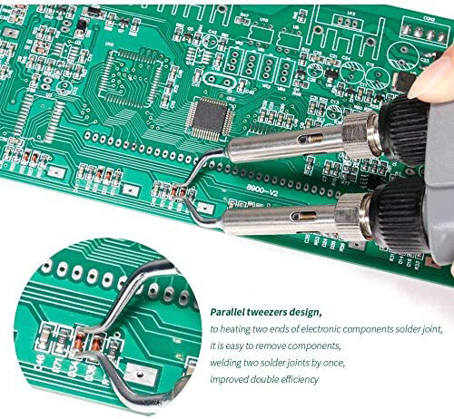
Curious what’s the recommended way to rework SMD components like this LED? Use hot air rework gun and tweezers to remove. Or use soldering tweezers like below, or some other approach?
Rework is a skill and can be dangerous if you’re heavy handed.
I use a lot of flux, and a combination of a soldering iron and a hot air rework wand. It helps if you can cut the part in pieces.
For an led, I would probably just use my soldering iron and flux. I bet I could get one side hot enough to melt, then make the other one hot enough, and a quick tap on the first side would release it to my tweezers.