Z depths and X Y - Issues have surfaced

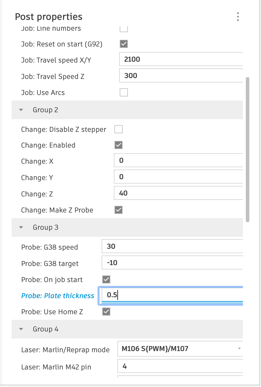
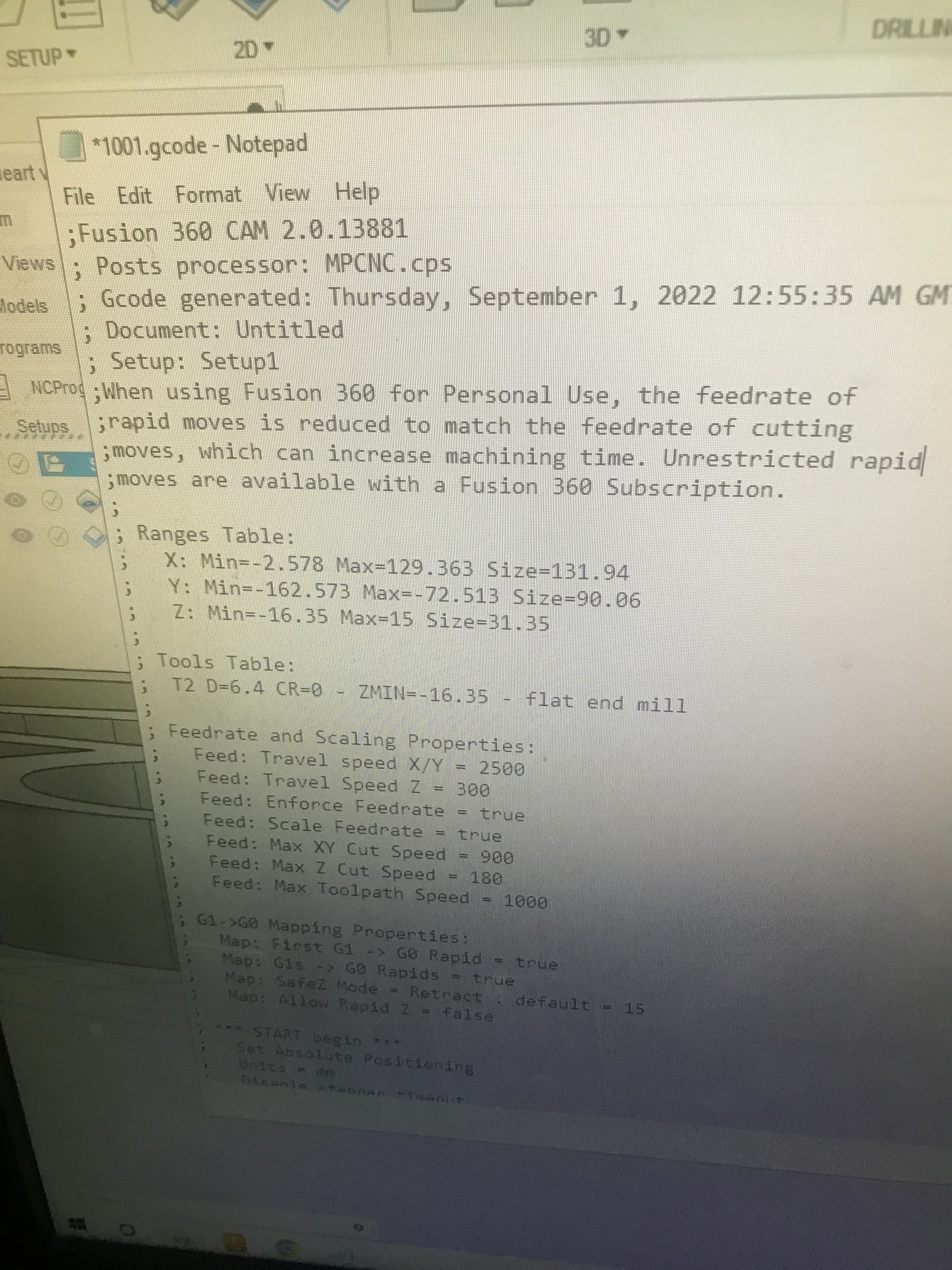
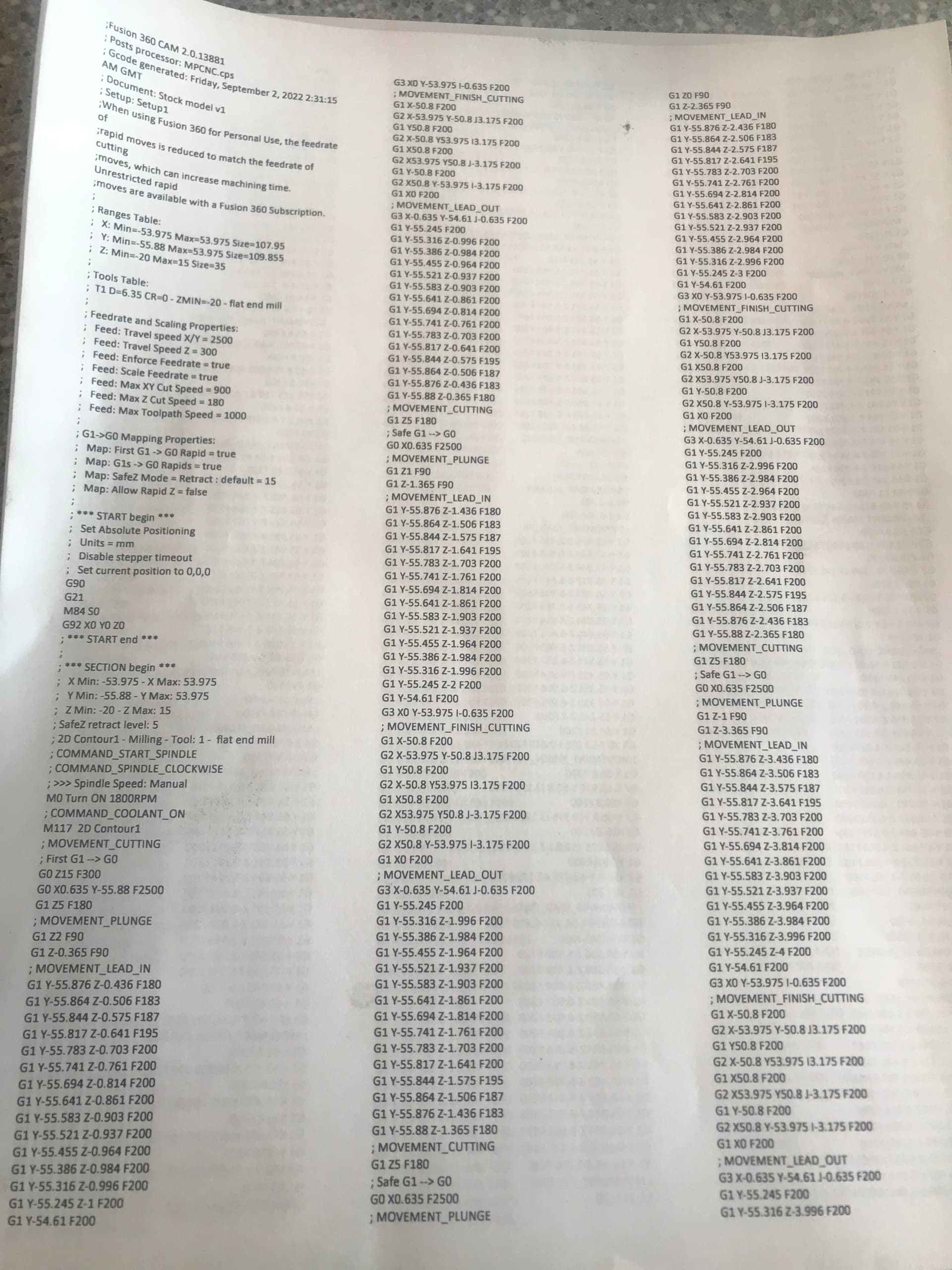
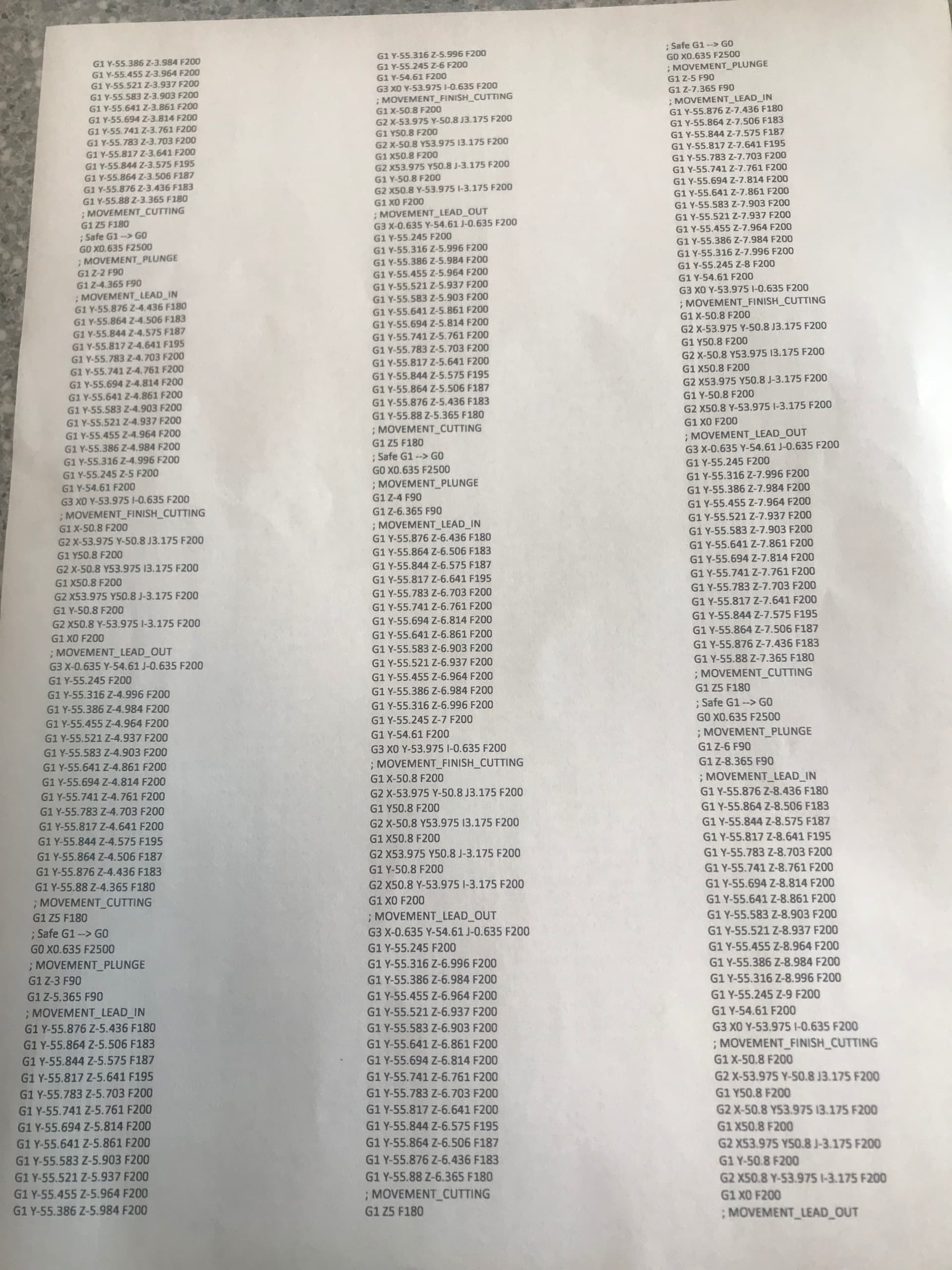
Got over the post processor hurdle, we’ll kind of anyways. Did some svg converting and then changing some things up.
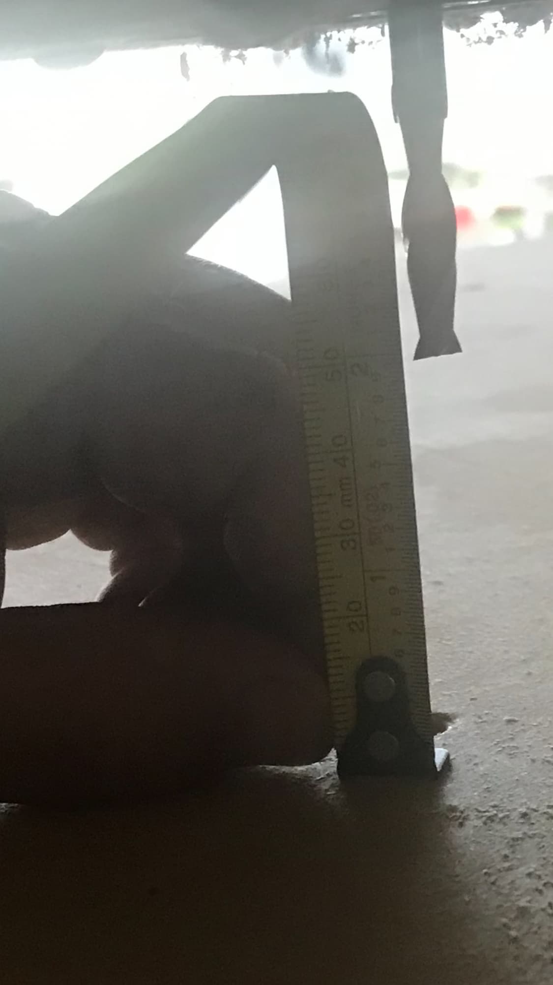
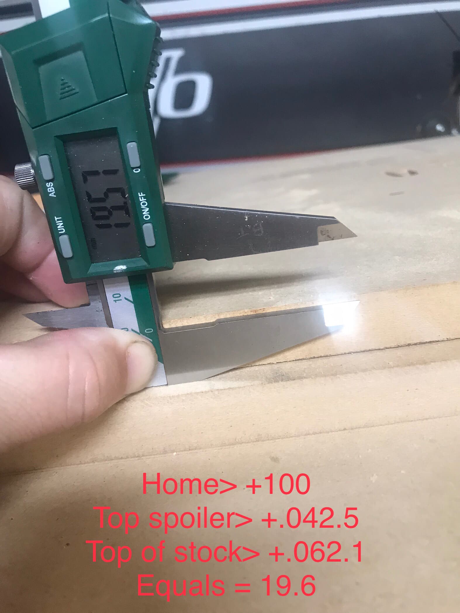
Touched off zero, however I was concerned with the z being off but I measured form left to right with calipers didn’t seem that different.
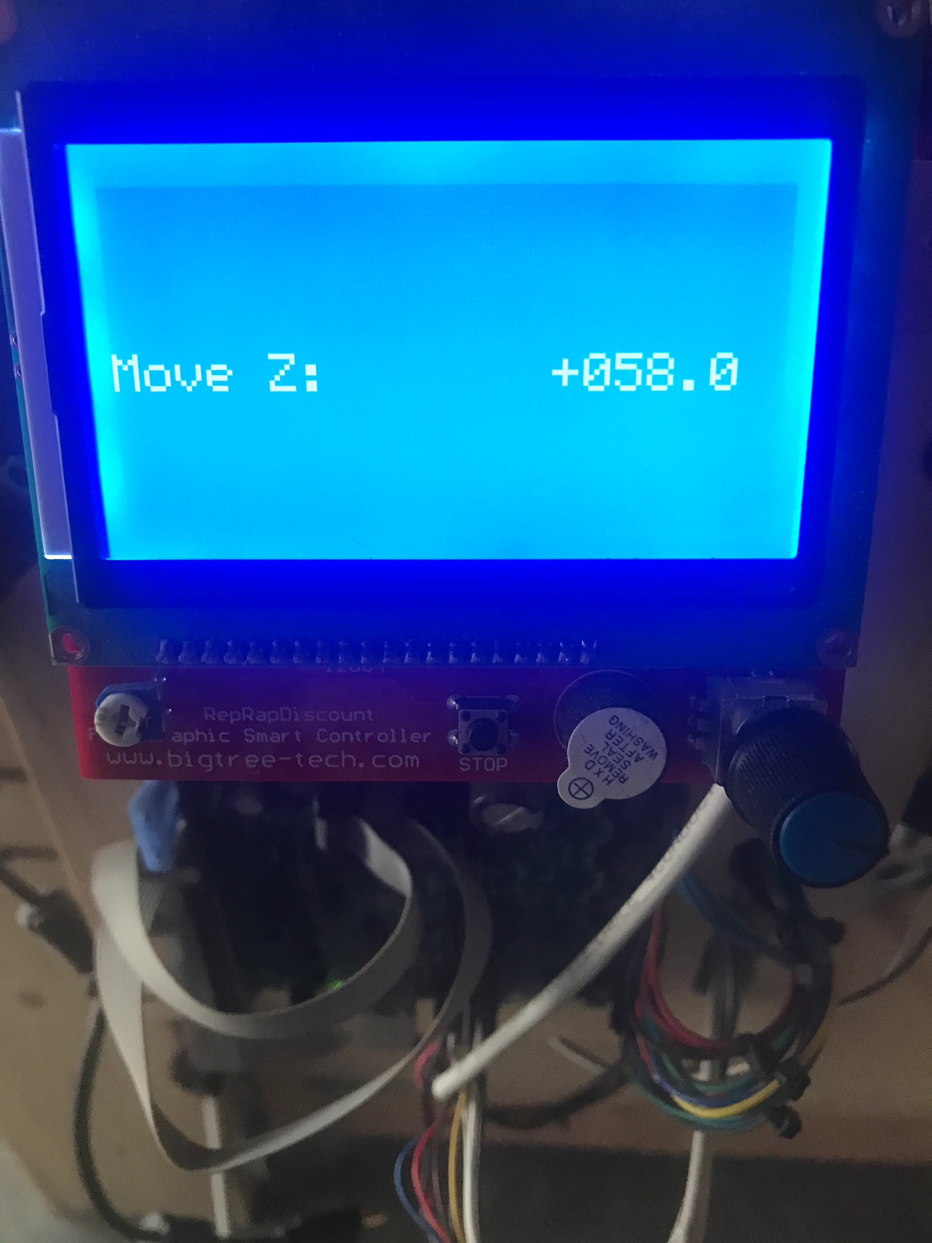
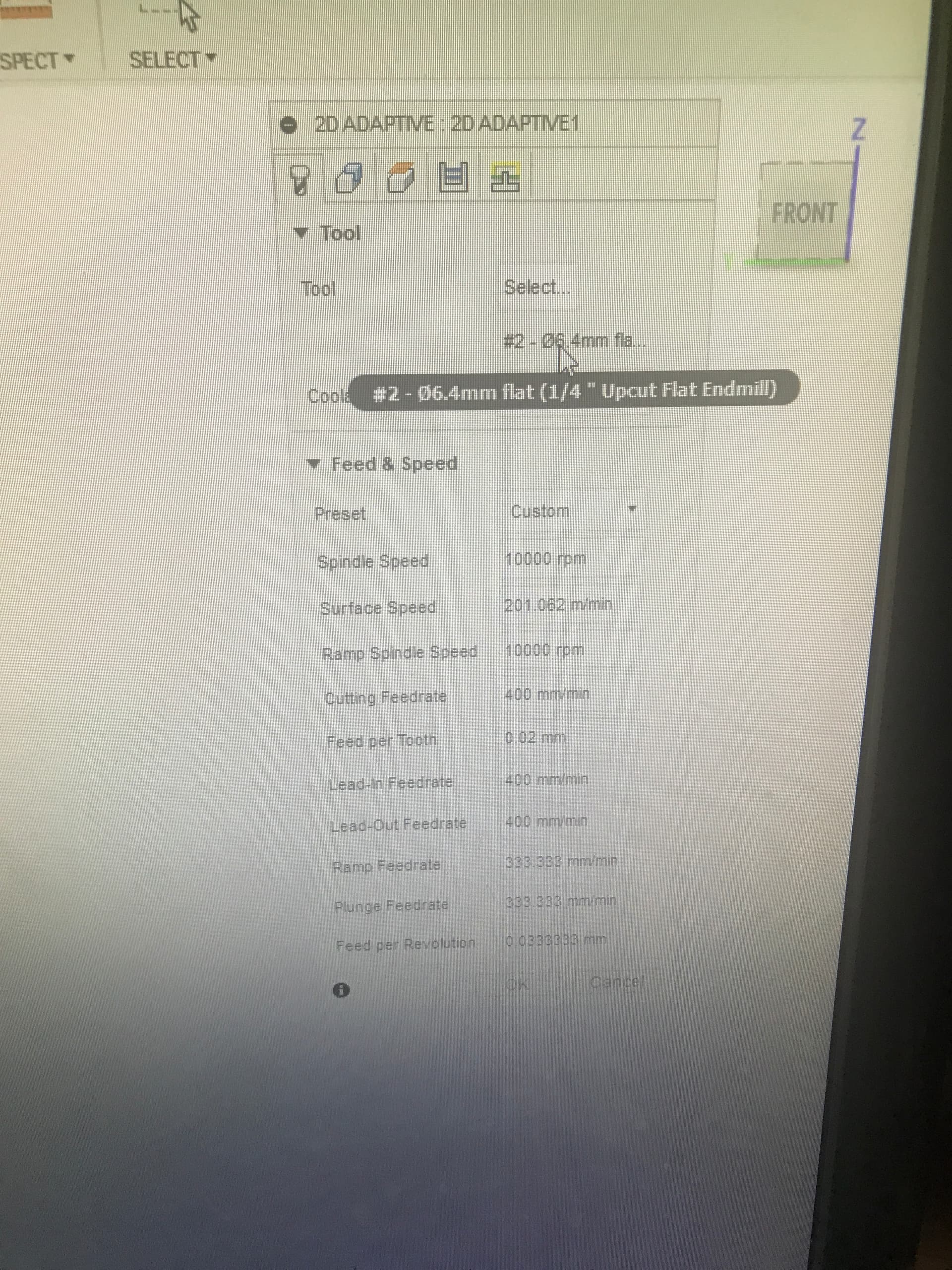
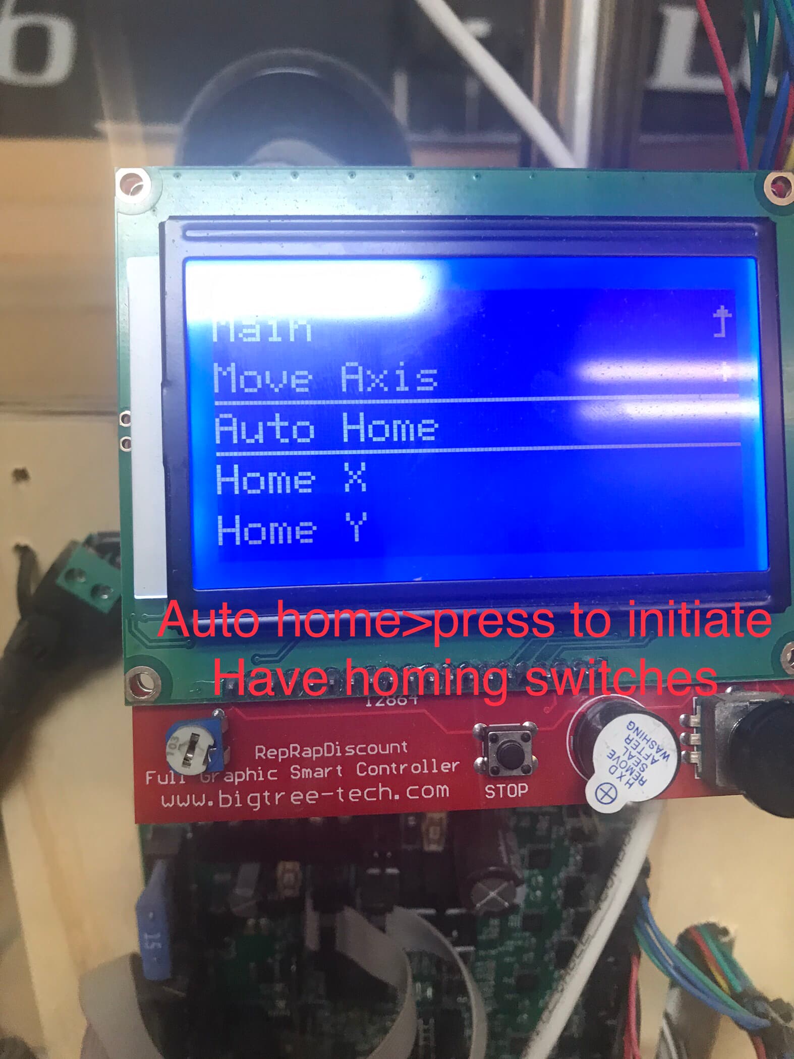
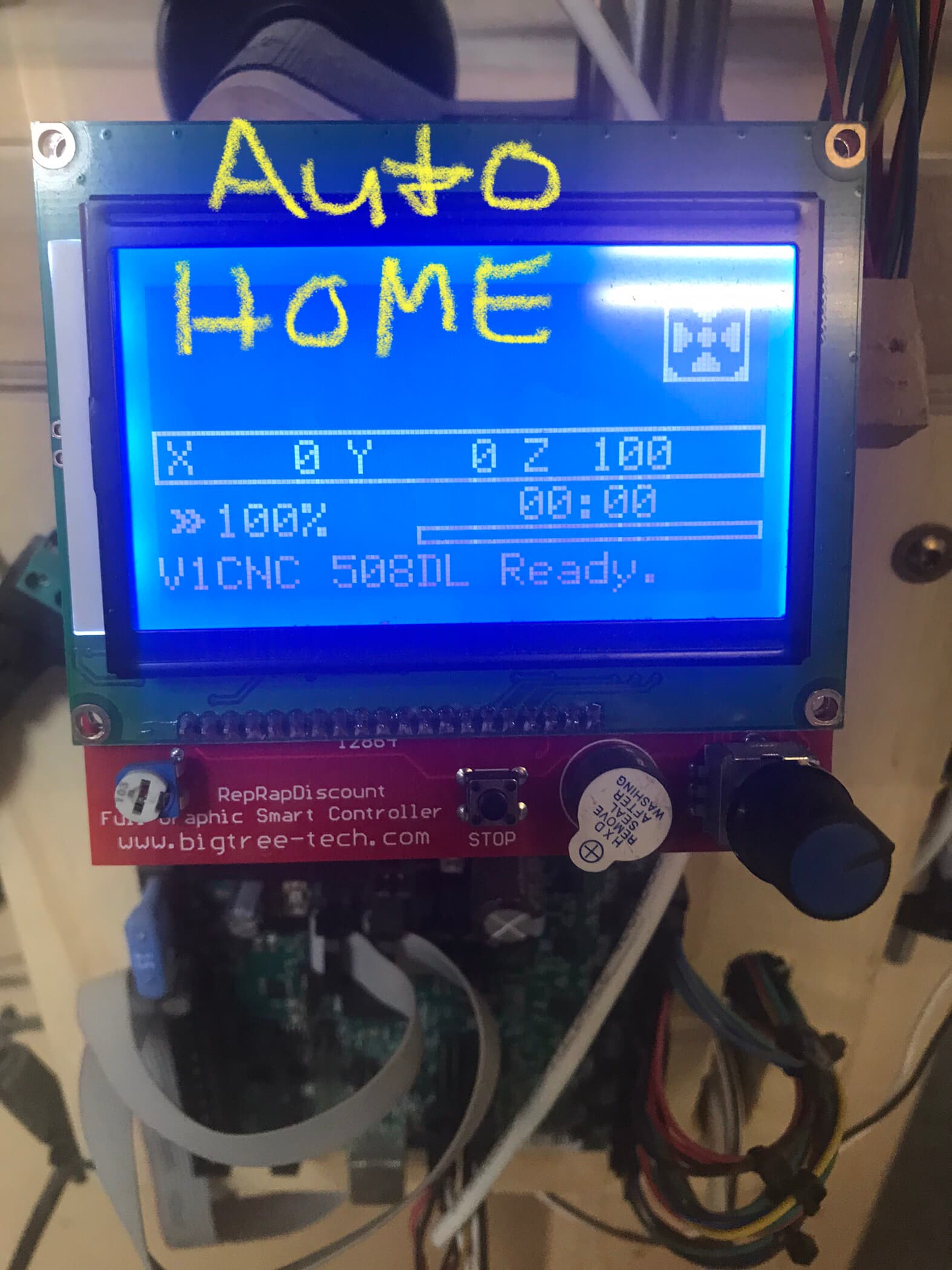
Seems to home fine to the naked eye, however had the spindle speed factored at about 13000 on the dealt router.
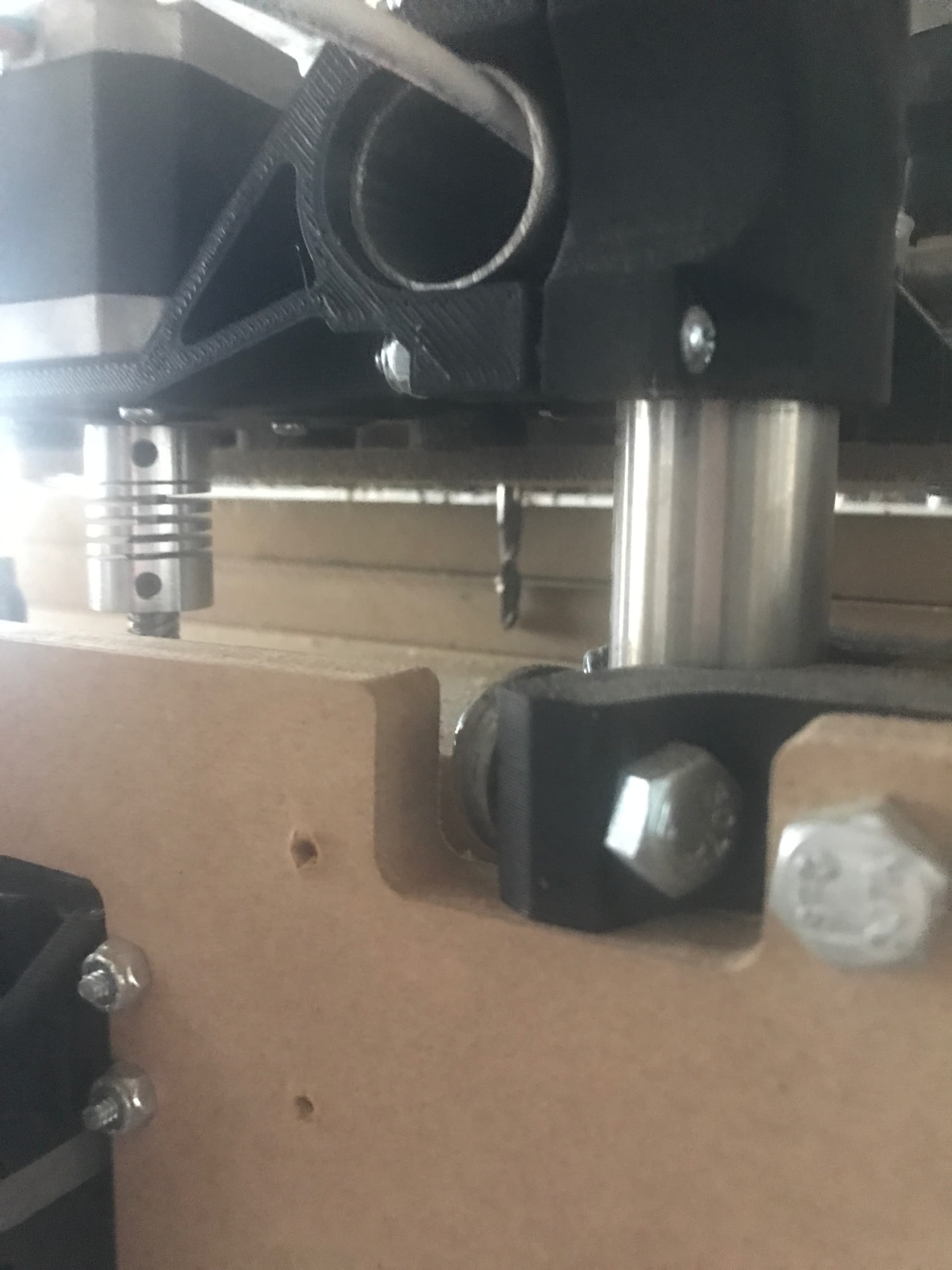
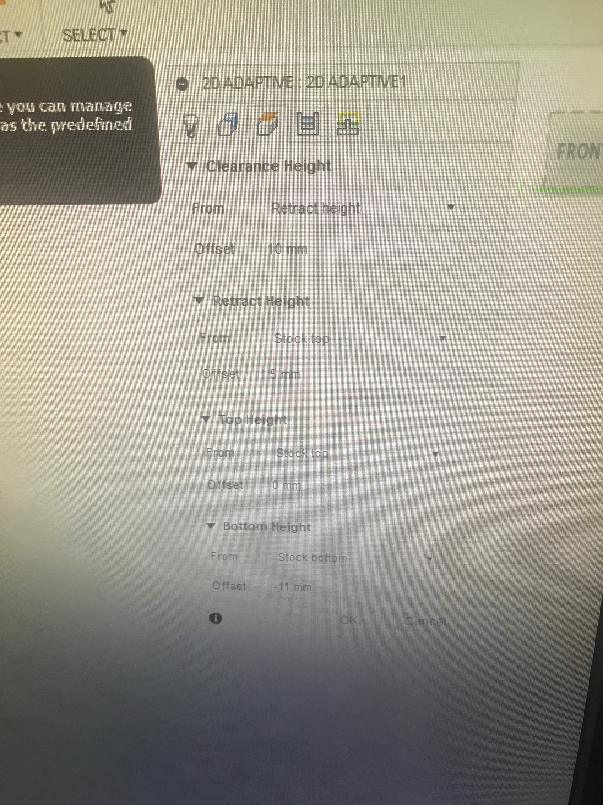
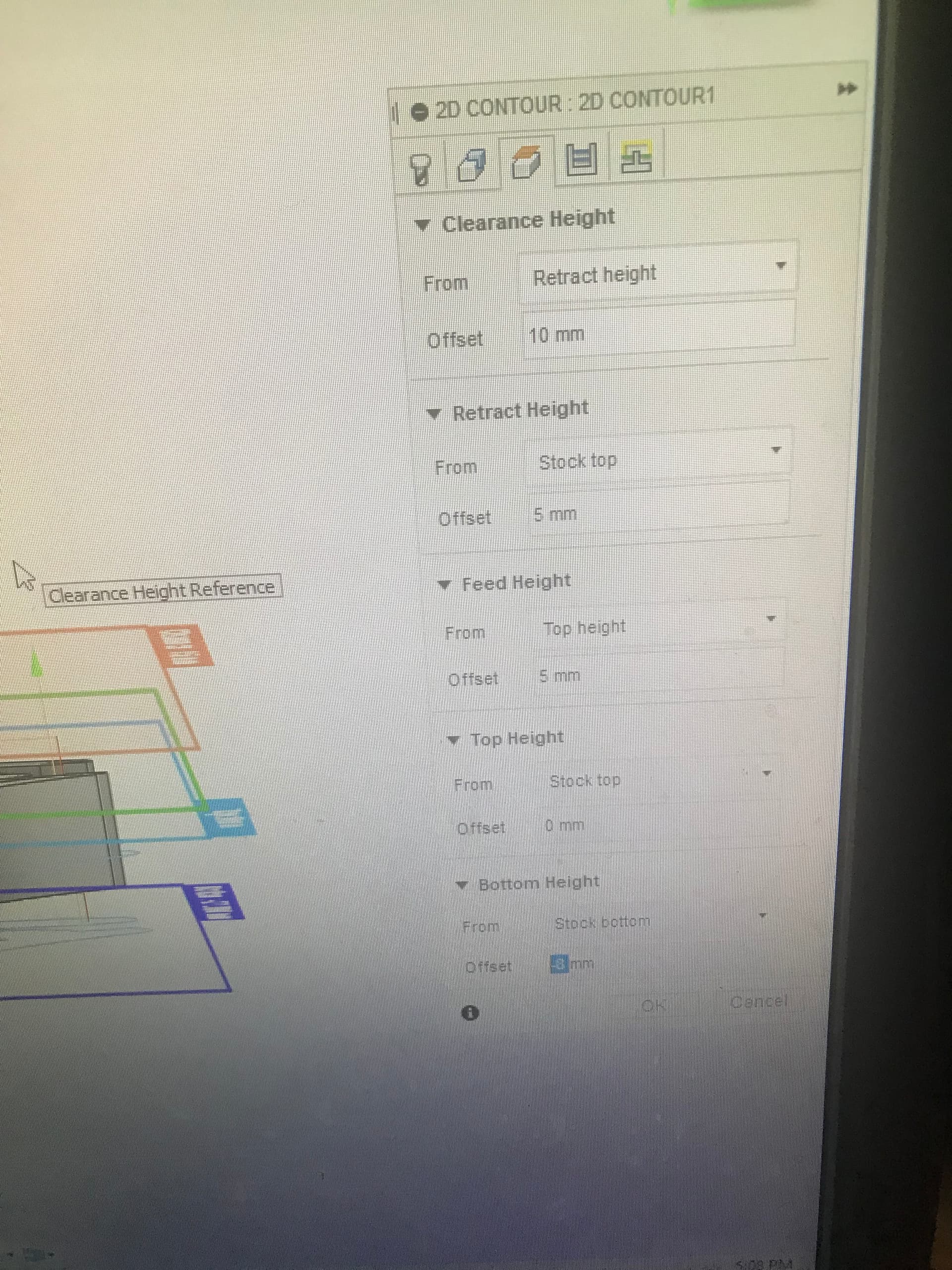
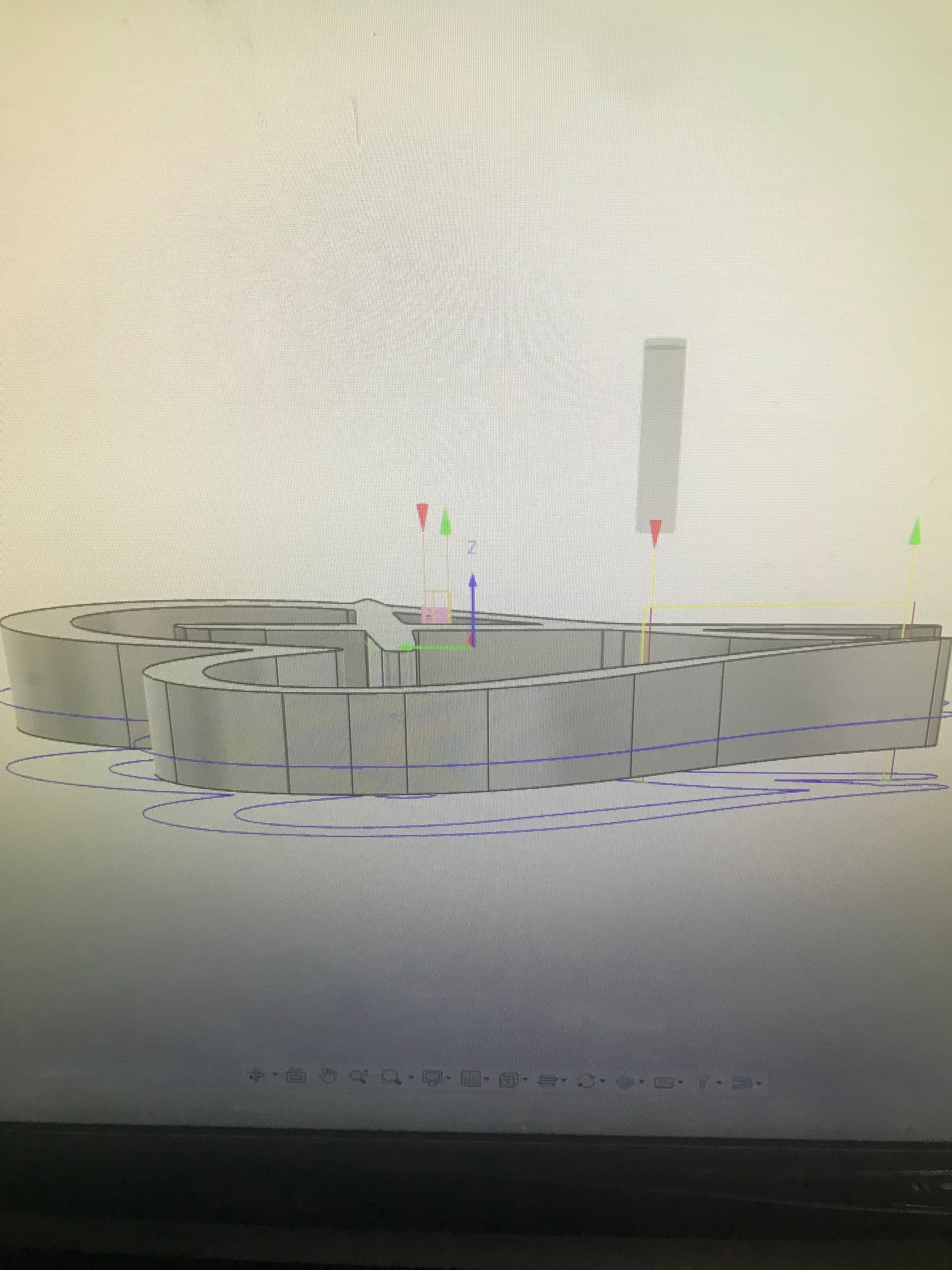
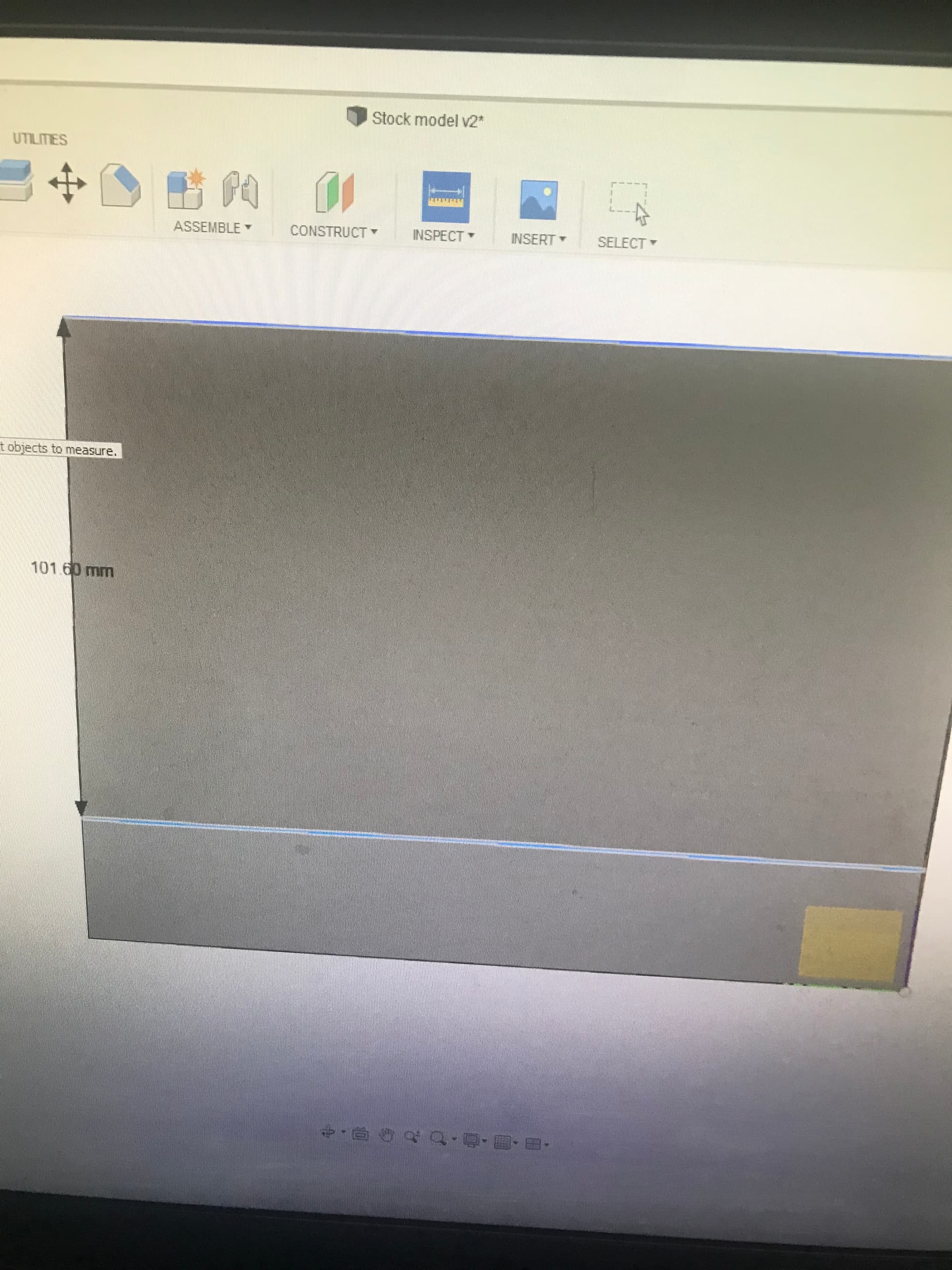
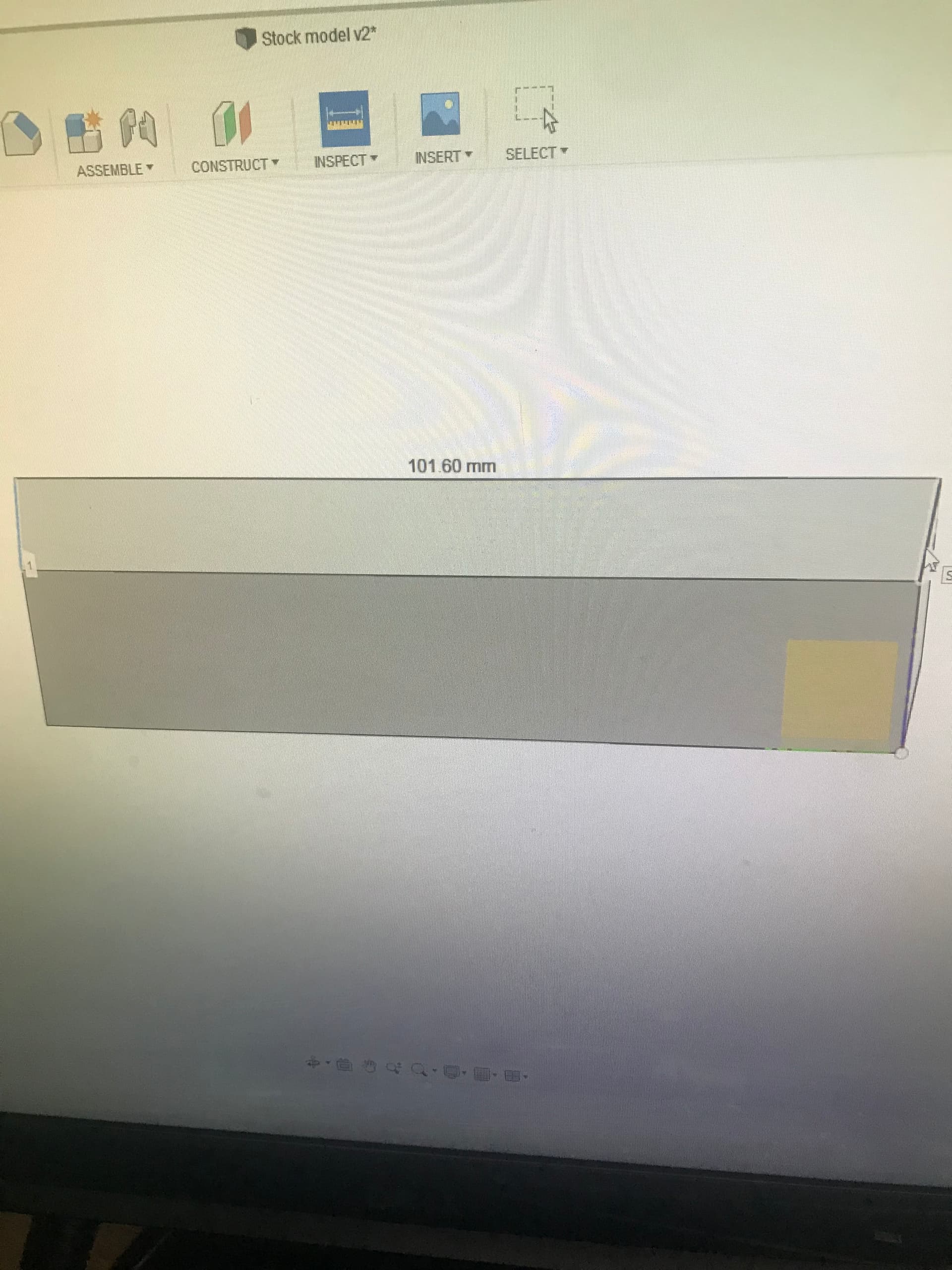
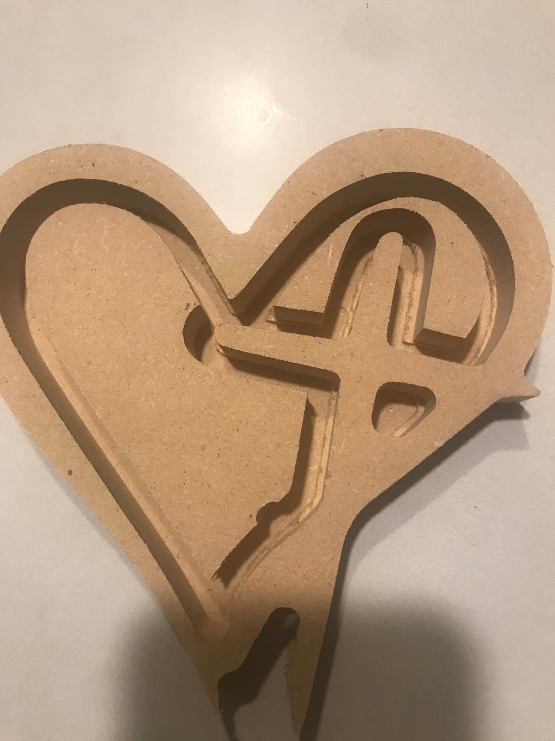
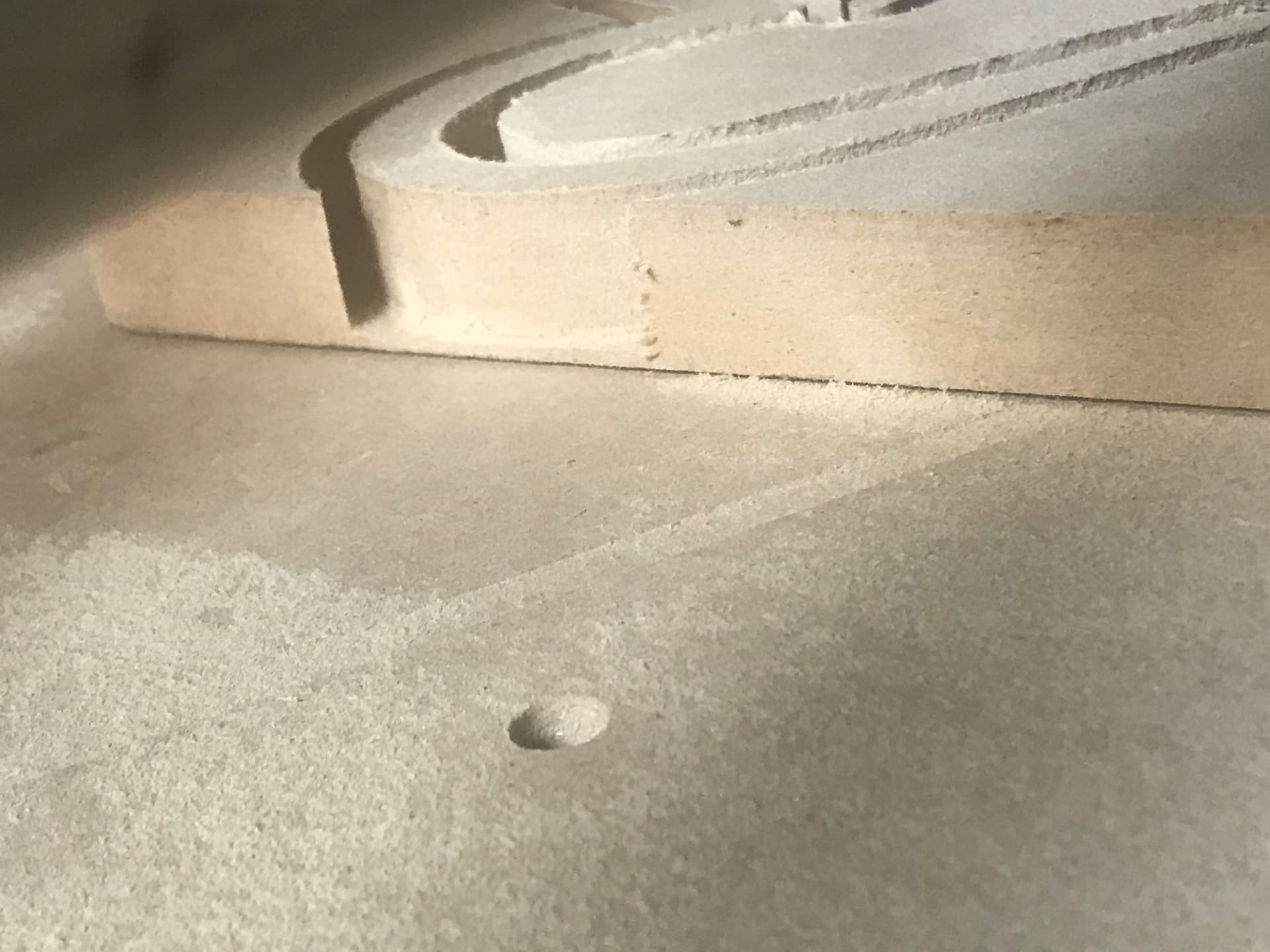
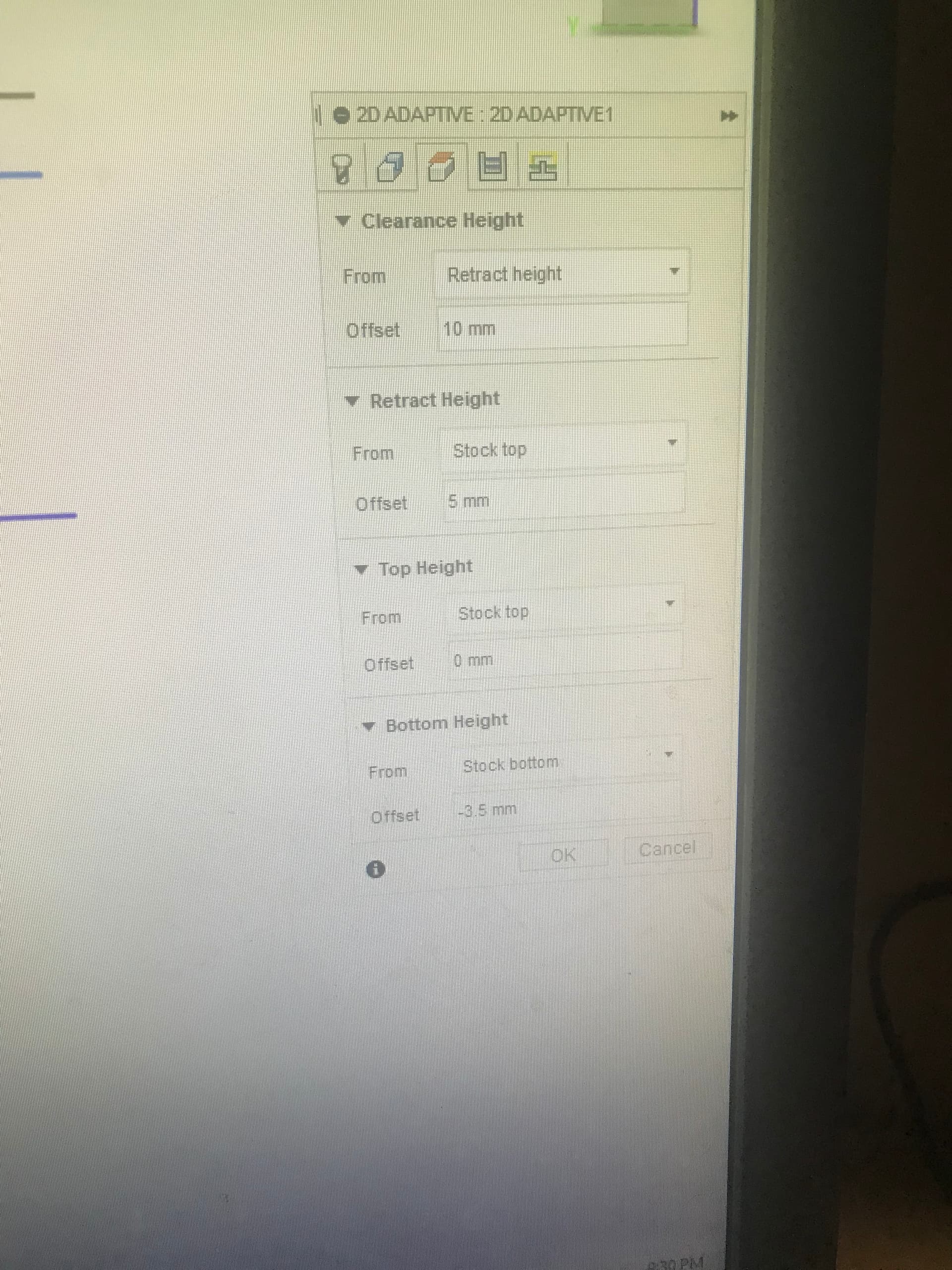
Problems: i modeled the depth of cut to go to model bottom, even offset it negative by 8 plus mm and still never broke through. There’s about a .020 or better ledge all the way around the bottom of part.
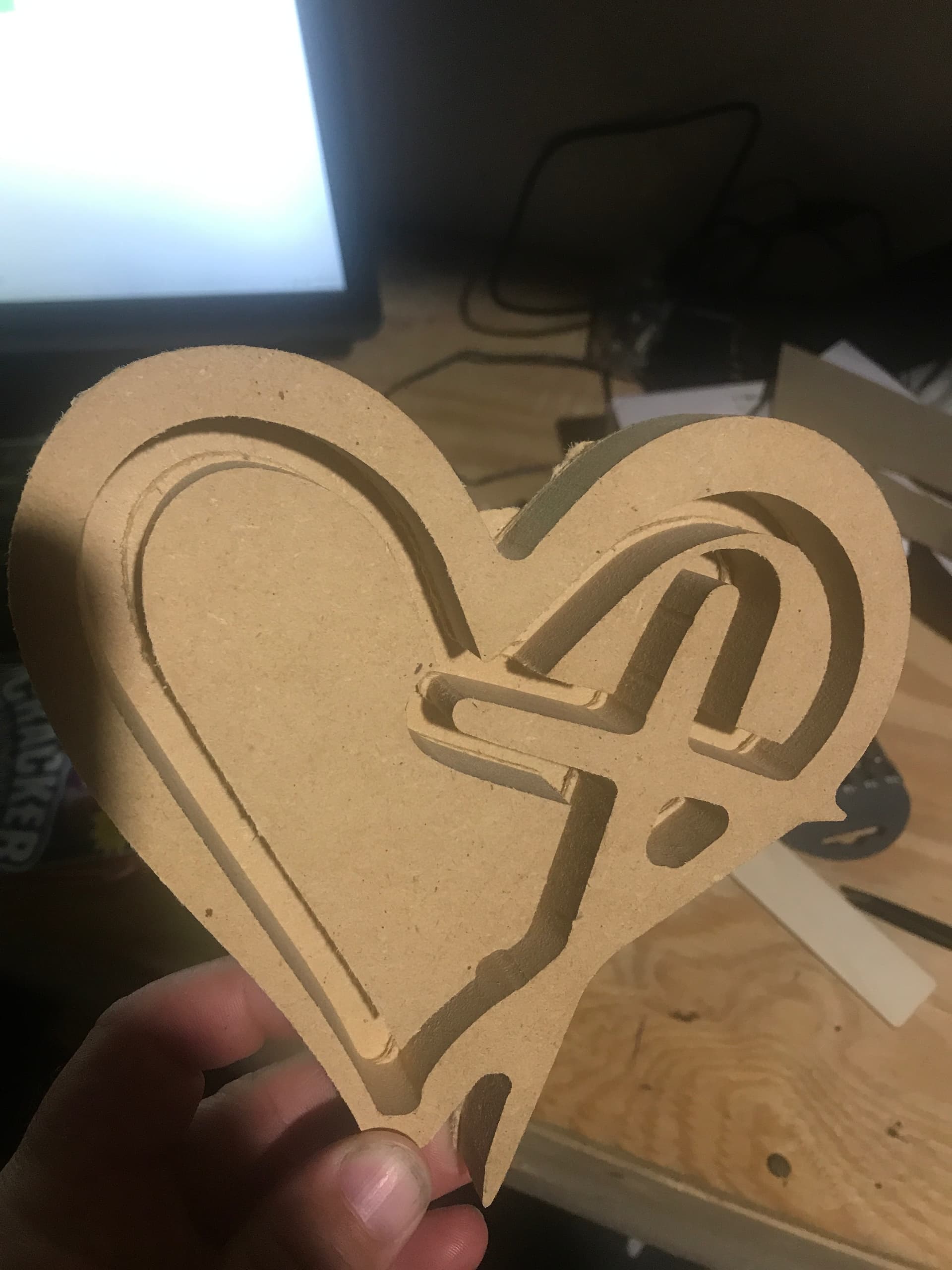
Inside the contour there is some serious deflection/z values that are obvious. With that though work holding for that part was no more than double sided tape (didn’t have a good way to clamp with inside countour and outter) therefore maybe some vibrations of the Mdf would leave that ??? :man_shrugging:t2: The endmill was a uncut 1/4 for it choked up as much as can in the router.
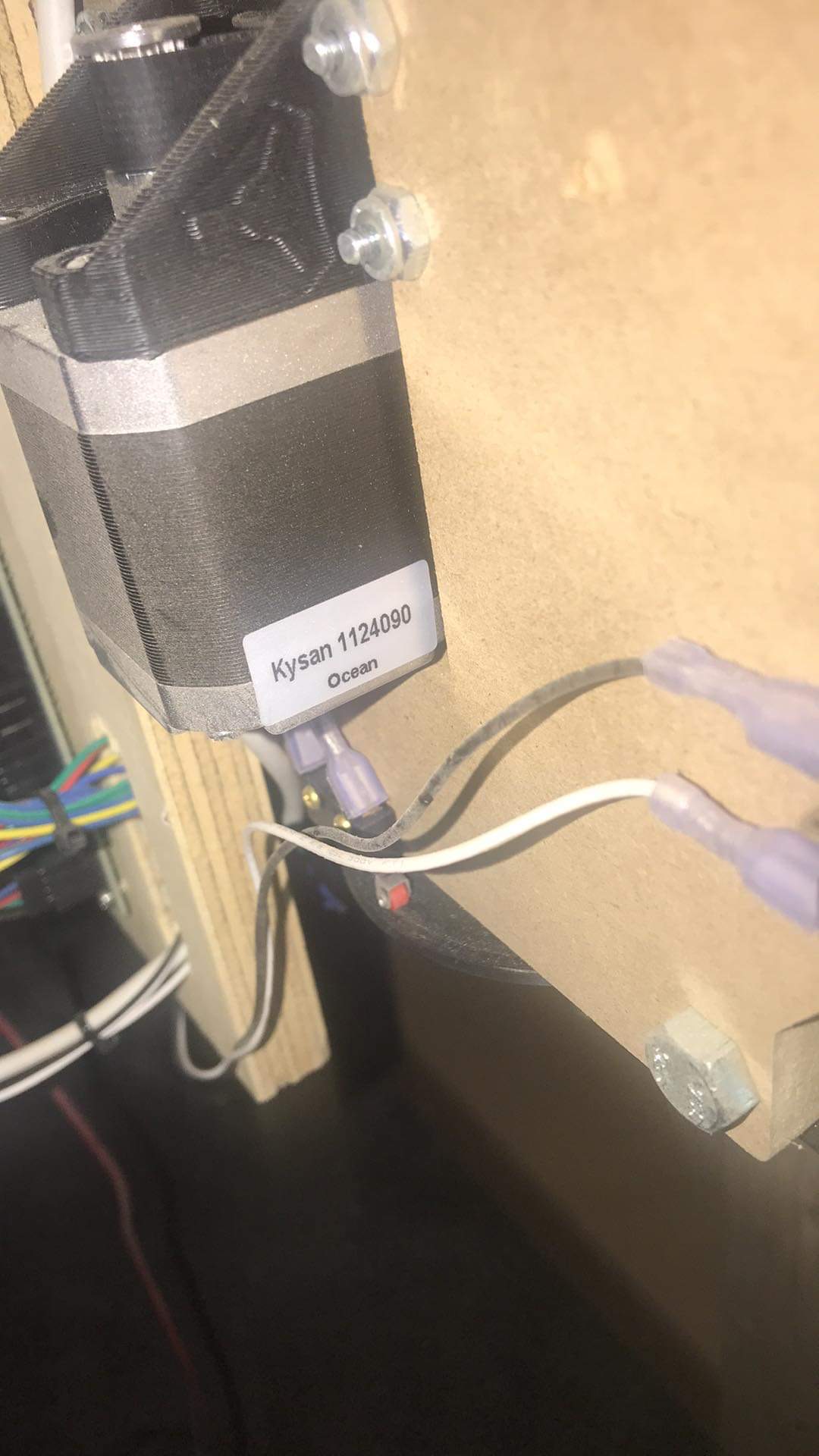
I do believe may be some belt issues on the y axis closest to the controls.
Open to any suggestions to try and clear this up.


Making progress In this lowrider saga but, still a lot to learn and figure out what key things to correct these issues.

Sure glad my post isn’t me just constantly hollering about the post processor lol

However, if anyone does see something that stands out that maybe is playing a roll in these inconsistent depths or walks having material left on and at the bottom. Let me know! I’m open to constructive criticism.

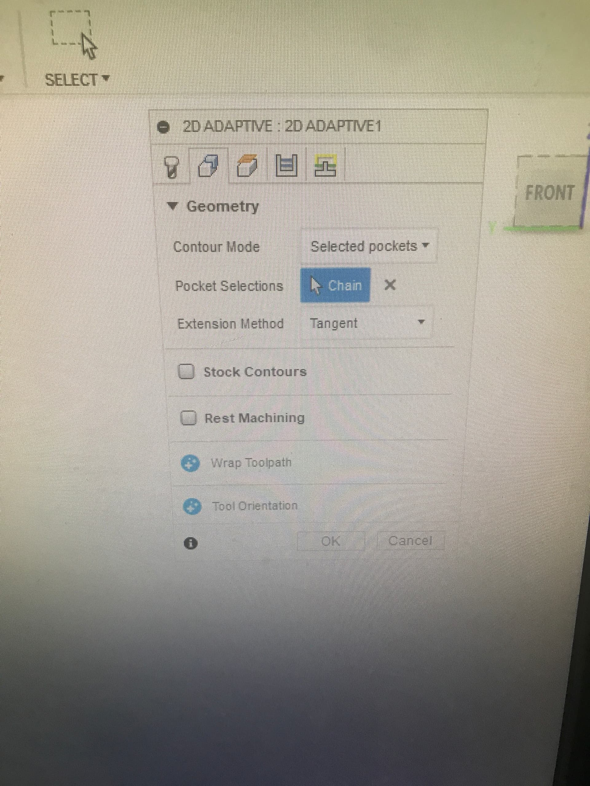
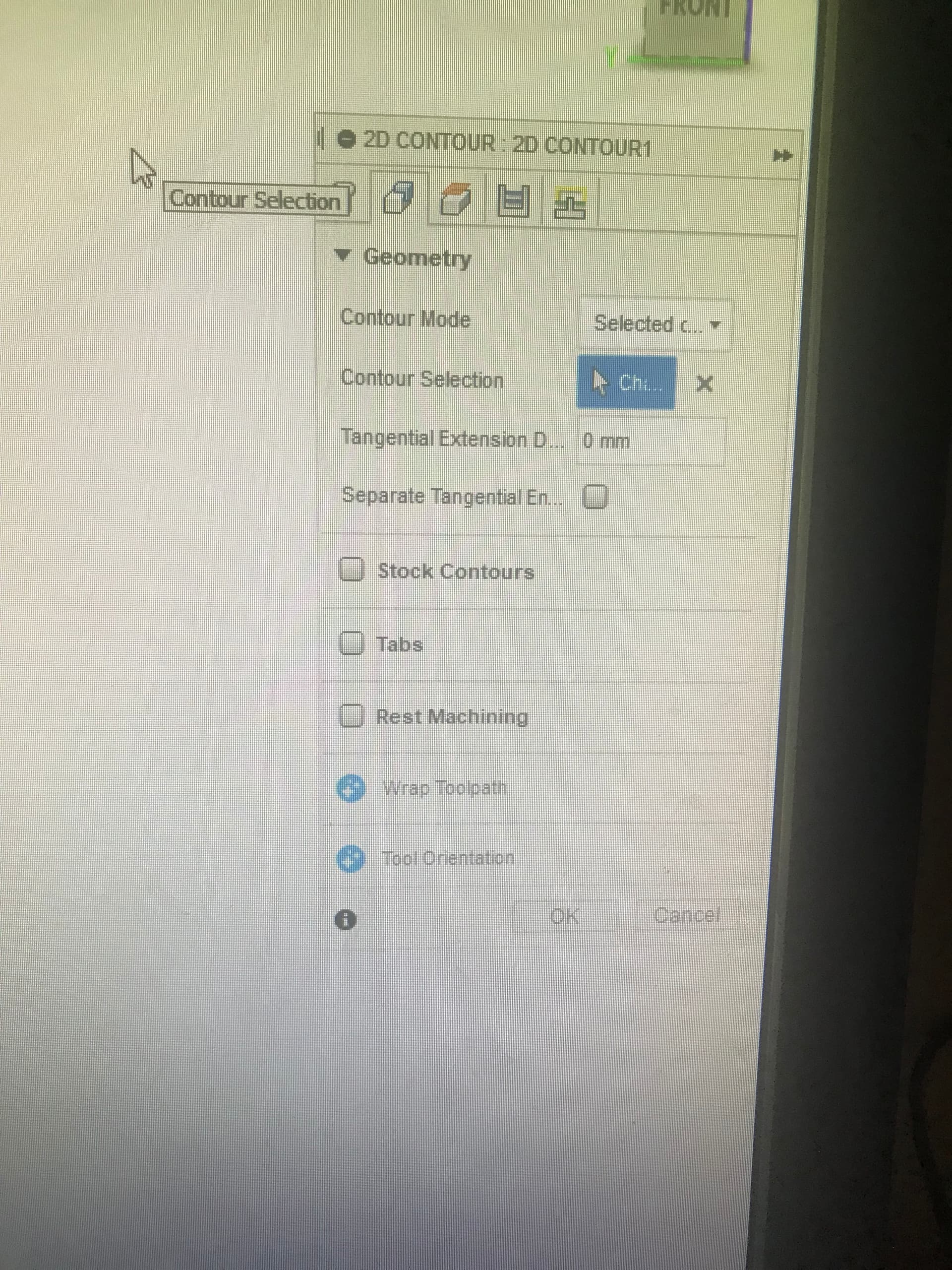
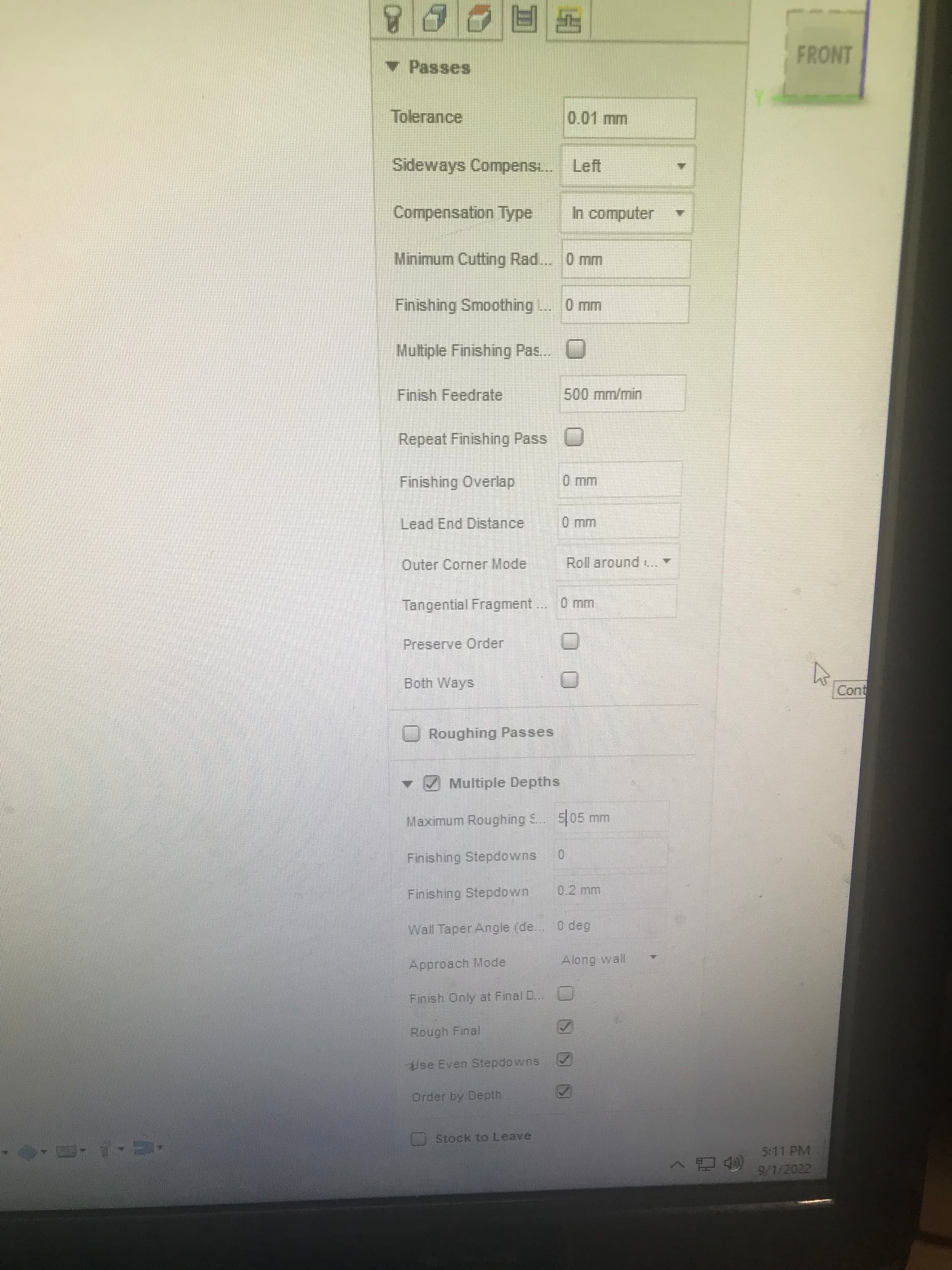
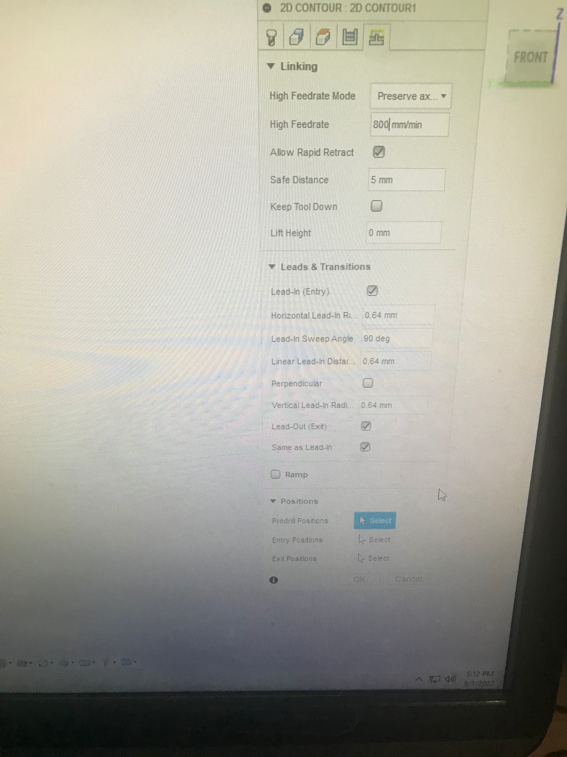
Before I forget after looking at the part almost looks like there’s maybe a cutter comp setting I don’t have set right. It is set to climb milling.

Thanks fellas
I’m trying hope someday I’ll have it down

I always have my bottom Height set to 0 mm

On the post-processing side.
What does your probe: plate thickness show?
Blue rectangular in the picture.

Reading through here, I’m not sure of the failure point. You are either 1) losing steps, 2) have a mechanical failure, 3) setup your job wrong, or 4) have firmware issues. Consider doing:

  • Posting your g-code file here along with the measurement of your stock thickness.
  • Put the pen back on your machine and have it draw a square of set size and measure the result.
  • With the pen touching the spoil board, raise it electronically to 50 mm or so and measure the result.
  • Mark your bit in the collet so you can see if it moves during cutting.

Just looking at the Z issue, my first two thoughts were 1) you don’t have the steps per mm set correctly, or 2) the bit was not tight in the collet and slipped up in the router.

That’s what I’m afraid off all those things, collet wouldn’t be an issue to fix but others… not so easy.
I can post the g code file after work with the stock size.
Bummer deal man, just when I thought we were off to the land of making cool stuff :confused:

Update! To original post from this am!

The collet and endmill was still tight!
@robertbu well according to the screen from zeroing the z on the wasteboard and setting that Z0 > moved up as close to the homing switches and it appears it’s off. As I would assume numbers should match.

^ actual with tape from zero

Here is the screen display from the same zero

Along with that… it’s def something for the min z in the processor that is not allowing the z to go down any further.


As I handled the Z down past the spoiler board and my cut material and it’s almost bottom out and still travel.

This is gonna get lengthy but, Here is the gcode file i punched out last night at 11 pm before giving up.

See photo’s regarding the limit z values


For starters I did just see that the z min is set to Z-16.35 which limits it out im guessing? As i was needing More travel in the z. which makes sense why it wouldnt go down anymore than -16.35
Each tool path generated has its own z min setting and at the top of the post it has one listed. Thought about typing z-20. MM MIN but I’d have to adjust all of the code to correspond
What would be the solution for that?

I also will be uploading my fusion 360 tool path screen shots, as that way in case im missing something or from user experience, pushing it to hard which is creating the uneven cuts or bad step overs.
2D adaptive pocket


Here is the other tool path for the
2D contour:


The material was 19.07 ish mdf board.
Open to any help!!!

Measured the first adaptive milling pocket and it showed about 16.9 mm deep when it finished. Which is a ways off from the modeled thickness of 19.07 mm plus an additional -8.0 mm below model bottom . At this point I’m clueless how to get the scale right for the z from zero to the doc to match.

For us on the forum, solving problems is often like trying to solve a crime by a brief look through a keyhole. We get very limited information, and, from that information, we make informed guesses as to the problem. At this point, I’m pretty lost about your specific issue. With that in mind, I suggest taking a number of small steps to make sure everything is working.

Step 0: Let me know what kind of control board you are using. From the display, it is likely either a Rambo or a Ramps. If it is a Ramps board, let me know what stepper drivers you are using, and what firmware you are using. If you are unsure of your board, post a picture.

Step 1: Check the grub screws on the connector between the Z stepper and the lead screws. I don’t think you have an issue here, but it is a common source of Z issues, so a quick check is warranted.

Step 2: Check the steps per mm for the Z axis. Put a piece of paper on your spoil board, lower your router electronically (not running) until it is touching the paper. You should be able to move the piece of paper, but it should drag on the bit. Record the Z height off your display. Next repeat the process using a piece of stock. Subtracting the first number from the second number will give you the amount Marlin thinks it moved up to the top of the stock. It would be close to the thickness of the stock measured by a ruler. If it is significantly different, let me know by how much.

Step 3: I need to know exactly how you home your Z axis with respect to the stock. Where do you execute the homing? What do you use as the reference (top of the stock or the spoil board)? What code is executed (if you know)? If you use a touch plate, what is the thickness of that plate? And finally, what does the display read at the end of the homing sequence?

Step 4: Author a 2D contour cut of square in Fusion 360 and postprocess that cut to a g-code file. Upload the g-code file to a post in this topic. Tell me the width of the bit and the dimensions of the square you used in Fusion 360. For uploading, see this icon on the toolbar:

image

Step 5: Export your Fusion 360 file of your square contour cut to your local machine, then put that file in a ZIP file and upload it to a post. If you’ve never saved a Fusion 360 file to your local machine, or if you’ve never put a file inside a ZIP file, you may have a bit of a learning curve to make this happen. If you are stumbling on this step, posting the results of the previous steps will still be helpful.

Step 5 (optional): Dry run. Home your Z against a block of wood. Remove the block of wood, and with your router not turned on, run the g-code file. See if the movements are what you expect.

My guess is your issues are related to Step #3, but I’d like to cover all the bases and get you running.

1 Like

Step 0 - The board The guy I got it from said it was a reprap rambo V1.4 board, added the picture of it and also added the picture of the stepper motor that is on the machine. The firm ware I dont know exactly what it has however, I know he said he built this couple years ago or year and a half. Dont know if that would matter what was available at that time. Im getting another computer this weekend to put in the garage but, as of right now I dont have a lap top to plug in usb and maybe see if i can locate what it has? If thats even possible.


Step 1 - I did check the screws however, didnt have the exact size of wrench, will bring my set home from work tomrrow to double check again. They both had four in each coupler, only thing that looked odd is they werent evenly ran in (screwed into bottom point). I dont know if that matters but, i can send a pic of that tomorrow and add to this post.

Step 2 - As listed in the photo below. I Use the auto home function when i power up the machine. Once i do that the machine will show zero for X and Y axis’s and Z will show positive +100 at the home position on the display. I jogged it down to the spoiler board, used paper and got that at +.042.5, then i Didnt zero anything i jogged it back up above the stock material. Repeated the process and got that at +.062.1. Which those to subtracted from one another comes out to about 19.6. With the calipers i measured down to the spoiler from top of stock i got 19.57mm and some change.


step 3 - As for homing the z axis with the respect of the stock. If i understand that right, from talking to Jeff and others. I more auto home the machine when i power it up. Handle the endmill or tool over to my starting location (origin) of my model. From there i bring the z down, use paper and touch off. Once ive got it where my start point is. I go to my sd card, run my Setzeros.gcode file that contains G92 X0 Y0. Once thats ran then i go directly to my Gcode i generated and turn on spindle and go. I have not used the touch off plate at all, it is still plugged into the board. Also all the post processor touch of plate thickness in such is still in the post processor.
In the model I use Fixed size stock with 2 mm offset on all sides sides. No offsets for top or bottom. I did just notice, the Z height for the model was showing 20 mm??? Not sure why it defauled to that. Maybe thats part of the issue? Modeling it I Use model Top and model bottom (±8. mms) to mill through.

step 4 - The Stock model (square) 20. mm (extruded thickness) 101.6 * 101.6 (w * l)
Job set up - Model Origin/ Center for origin point.


Almost got to the point to share the mode. However, my personal hobbyist version blocked that option out.
1001.gcode (25.6 KB)
There is the contour Code.

Step 5 - I will run this contour code tomorrow possibly, If all looks scaled after you fellas who are much more seasoned than me check it out.

Appreciate you guys, looking forward to the days ahead where i wont be so green with these machines.
Thanks @robertbu Hopefully this info is helpful

onward we go.

These photos help. First, you have a Rambo board. The stepper drivers are part of the board, and the steps per mm are set in firmware. The values you display are correct for Z assuming you have the standard 4-start lead screw.

I forgot we are dealing with a Lowrider, which homes Z up. When I was referring to “homing” in my previous post, I’m trying to understand how you determine the top of the stock for your cut. On the MPCNC, this is done by homing the Z (or done manually). On the Lowrider, it is done by probing, or it is done manually. Note that the 100 for Z at the end of homing is not an accurate number. If you are not setting your bit to the top of your stock and then setting that as the home position with a G92, then this is likely the root of your issue.

As for the stock thickness test, I assume your stock is about 19.6mm thick, and therefore this test confirms that Z movement in the real world matches the movement on the display.

I’m going to jump ahead and give you a recipe for an attempt at a cut.

  1. In Fusion 360, in the Setup for your CAM, make absolutely sure you are picking one of the top stock points as the starting point for your job. Usually, I use the top of the stock and the bottom/left corner of my material, though sometimes I pick the top point in the center of my material. Either will work as long as you are picking your reference using a point that is on the top surface of your stock. This will be in the Setup for your CAM. And set up your job so that the height of the stock in Fusion 360 matches the height of your real stock.

  2. Home your machine.

  3. Electronically (using the display) navigate your router until the bit is just touching the reference point you defined in your Fusion 360 CAM.

  4. From the V1 custom menu, select Reset All Coordinates.

Verify that the coordinates are now set to (0,0,0)

  1. Run your job from the SD card using your display.

There are many different ways to set up a job, but I’m trying to give you a recipe that eliminates a number of potential problems and will either lead to a successful cut, or will indicate we need to look at mechanical problems.

@robertbu already appears different by using the menu. Makes more sense as well, it’s showing a negative value when I move it off that point. X and y show a positive and negative move as well off 0,0.
With me running that g92 file, it truly wasn’t setting that starting work plane to 0,0,0?? Appears obvious with seeing the values now make more sense.

1 Like

The Reset All Coordinates menu item executes the following code:

G92 X0 Y0 Z0

I’m not sure how you were executing your G92, but there was likely a problem if the menu is behaving differently. The g-code commands are case sensitive, so it needs to be an upper case ‘G’. In addition, you must have a newline at the end of each text line in the file. I found this out the hard way when Marlin was ignoring the last line in my files.

I’m hoping so, I created a file that had one line of code. Jeff told me to make and added that into my sub file. On my as card I’d have the G92 file, then my program. I’d execute as the following.
I’d go media > card> file - SETZEROS.Gcode G92 X0 Y0 Z0. I’d go to that file once I jogged to my spot. Then print from media. It would reset all my coordinates to zero. Then without moving the machine I would go to my as card memory again and click on the 1001.gcode (model g code file) and hot start print.
Here’s the pic of the sd card.

Don’t know if that works the same as the method you suggested or on the same principals. Just hoping the suggested way works for sure.

It should work exactly the same, but since it does not, we can check it out. Show me the contents of that file (open it with any text editor). And as I’ve said, you must have a new line after the last line of code in the file. The last time I checked (because I had a problem), without a new line, the last line in the file is ignored.

@robertbu i am gonna take pics of the code of that model I made 101.6x101.6 and 20mm thickness
Not at home but wanna see what line it is and where it needs to be inserted. This box has a ton of z ramping as I have the intent of maybe trying to use it. If we need to test it … I’ll load the pics in order of the code
Stock model code > troubleshooting


I’m confused. What I want to see is the contents of the SETZERO.GCODE file. It should have just a line or two of code. Pictures of g-code files, while having some value, are not nearly as helpful to look at compared to the digital file. You should be able to use the upload icon to upload a digital version of your files. For example, I can search out specific sections or lines in a digital file.
image

This. Wherever you touch off with your probe and set 0,0,0 must match the setup origin (which is not always the model origin).

To reiterate what robert said, decide where you want to line up the tip of your endmill to start the job, and pick that in the cam setup (first step before creating any toolpaths). It’s in the first panel, about 2/3 down and probably defaults to “box point” or something (you can also model a point, and use selected point, but don’t worry about that now). Then you’ll have to regenerate all your toolpaths in the Setup.

Once you set up and do your start routine at the machine, you should be able to send it to 0,0,0 and the tool tip should be in exactly the point you selected above in the setup. Otherwise, all the toolpaths are going to be off by however far off your tool is.

The min/max z at the start of your gcode isn’t setting limits, it’s reporting limits from the code, btw. Those are basically set in the heights tabs of the toolpaths (with modification by stock-to-leave).

1 Like

At work that’s the reason sent the pic. I’ll upload it when home as a txt .file.
Only code in that setzero file is

G92 X0 Y0 Z0

Nothing else in there just that just as I typed it.

@turbomacncheese dont believe I had the stock to leave selected on any of this. I could be wrong but I’ll double check when home.
The ogrin of the setup I believe I’ve kept the same however I’ll have to verify. Will report back once I can get home and change that type to a .txt and upload it. That way we can view it on here for you and @robertbu

1 Like

Hate to butt in with this comment but this is extremely simple to diagnose with Estlcam, Fusion cam is just insane to try and decipher which of the pages and pages of settings are wrong. I highly recommend estlcam. We could look at the first couple lines of your code and tell you exactly what is going on.

Maybe look at it this way. Do the job with estlcam if it doesn’t work right let us help you get it perfect, then try to replicate it in fusion. At least then you will know exactly what the steps should be and you will know where it is going wrong.

3 Likes