Hey There,
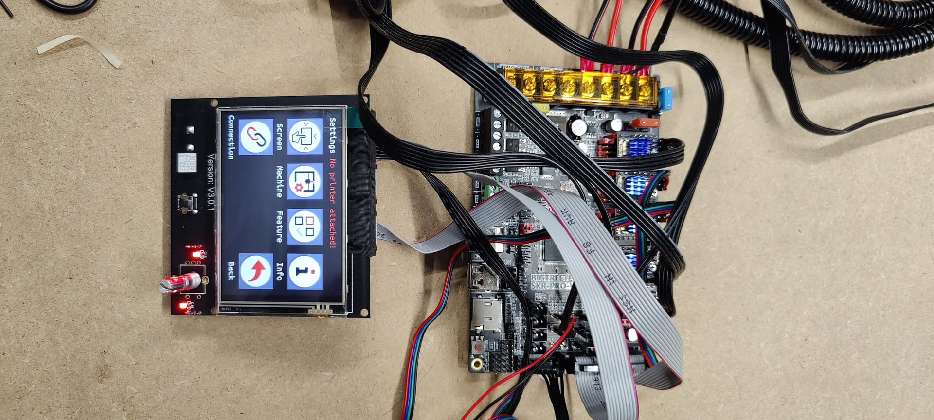
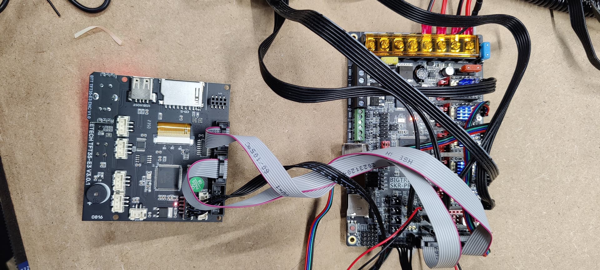
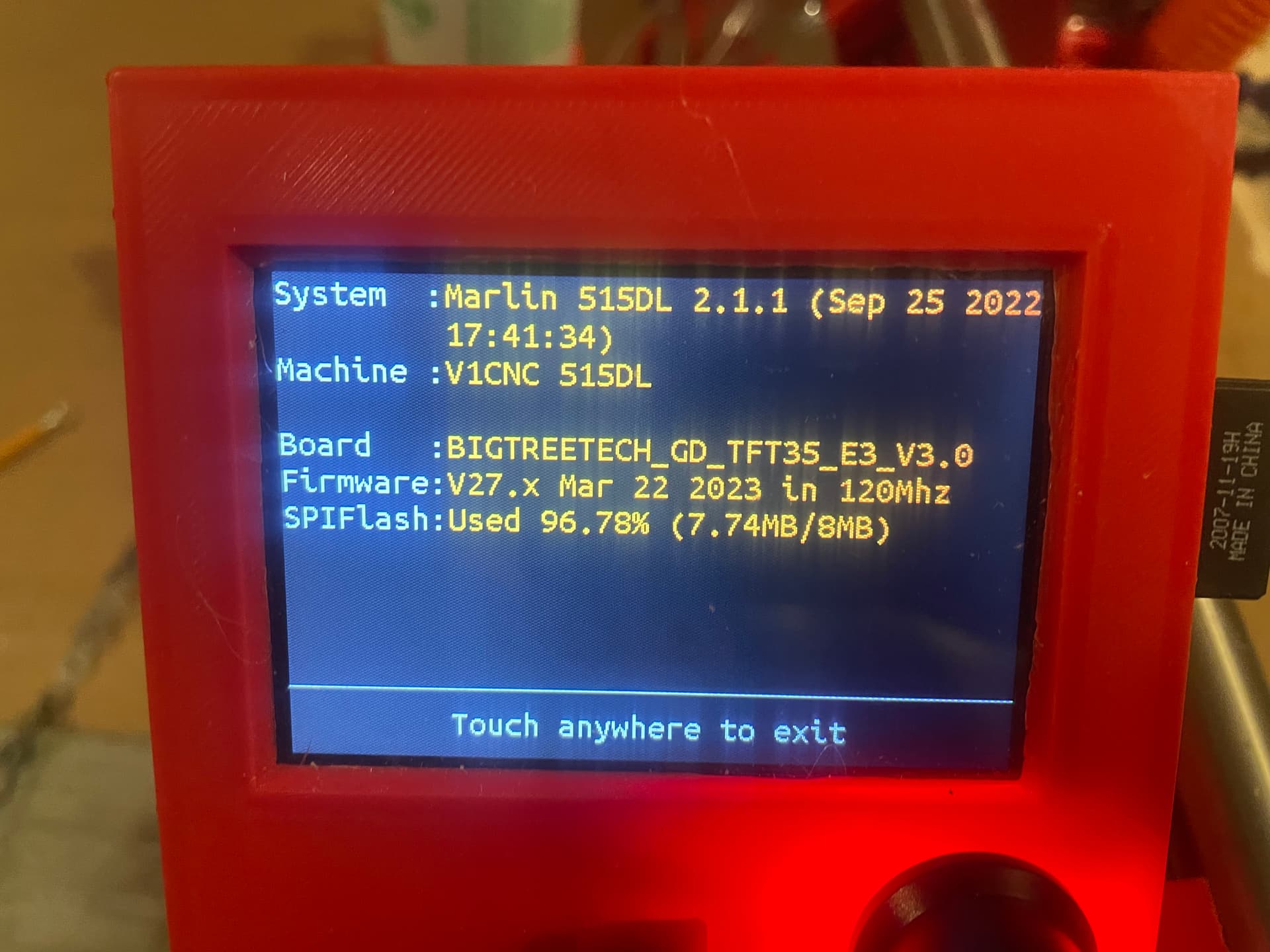
Well I finally finished putting together my Low Rider 3, but powering it on only gives me a “no printer attached” on the top of the TFT screen. I could select various items on the TFT but my steppers weren’t motivated. Marlin won’t load…just a black screen. I double checked my wiring, as well as the baud rate…all look 5x5.
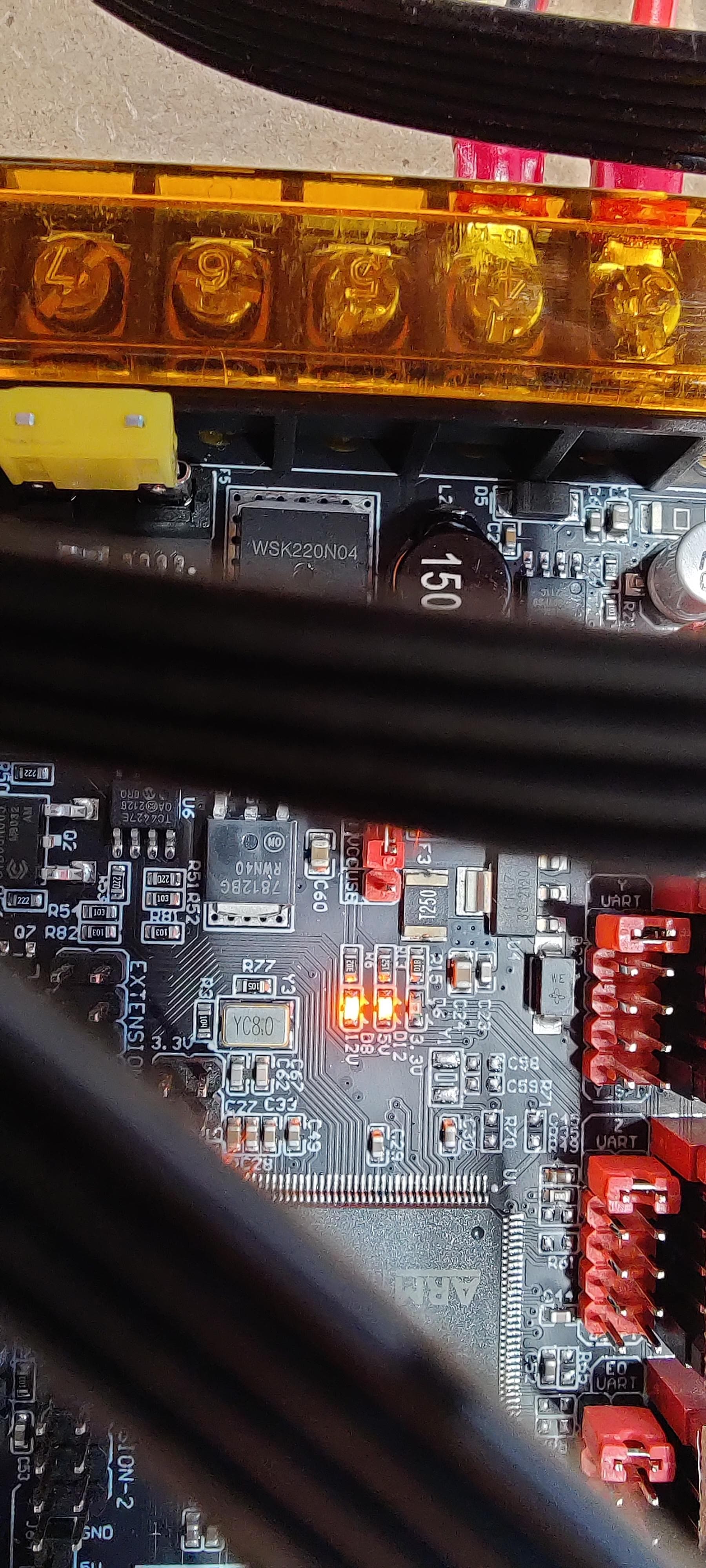
However I did notice that on the SKR Pro1.2 when power is applied with the provided power supply the 3.3V isn’t lit but the other two (5V and 12V) are.
Is my board toast? What are the chances of getting a replacement board? The only other thing I can think of is that the firmware is incorrect. I’m pretty sure I chose to have the lowrider firmware preinstalled when I originally ordered the kit but I don’t see what was flashed to the board…only that it was flashed. I attempted to reflash it but it never took…back to my power issue. What are my options?
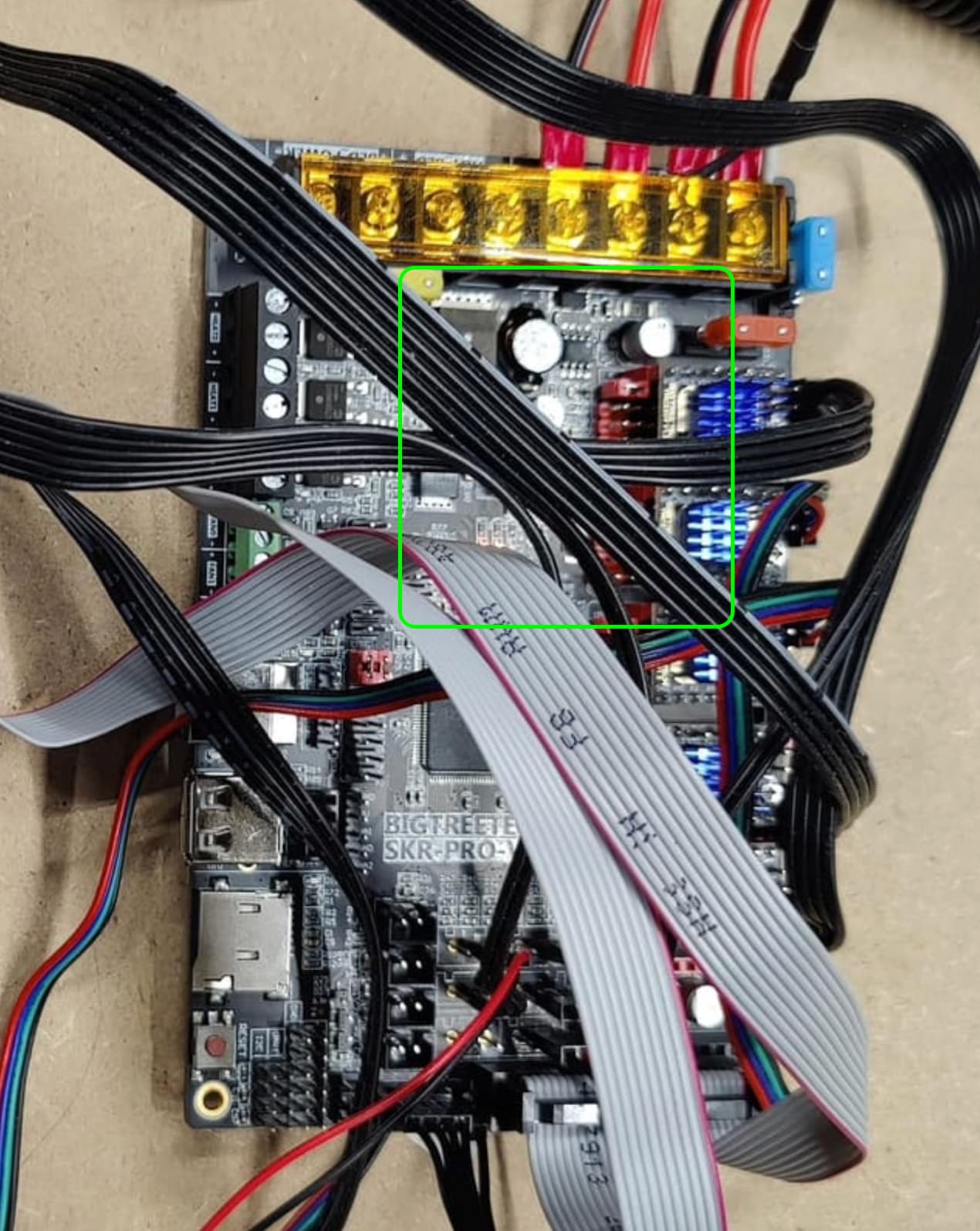
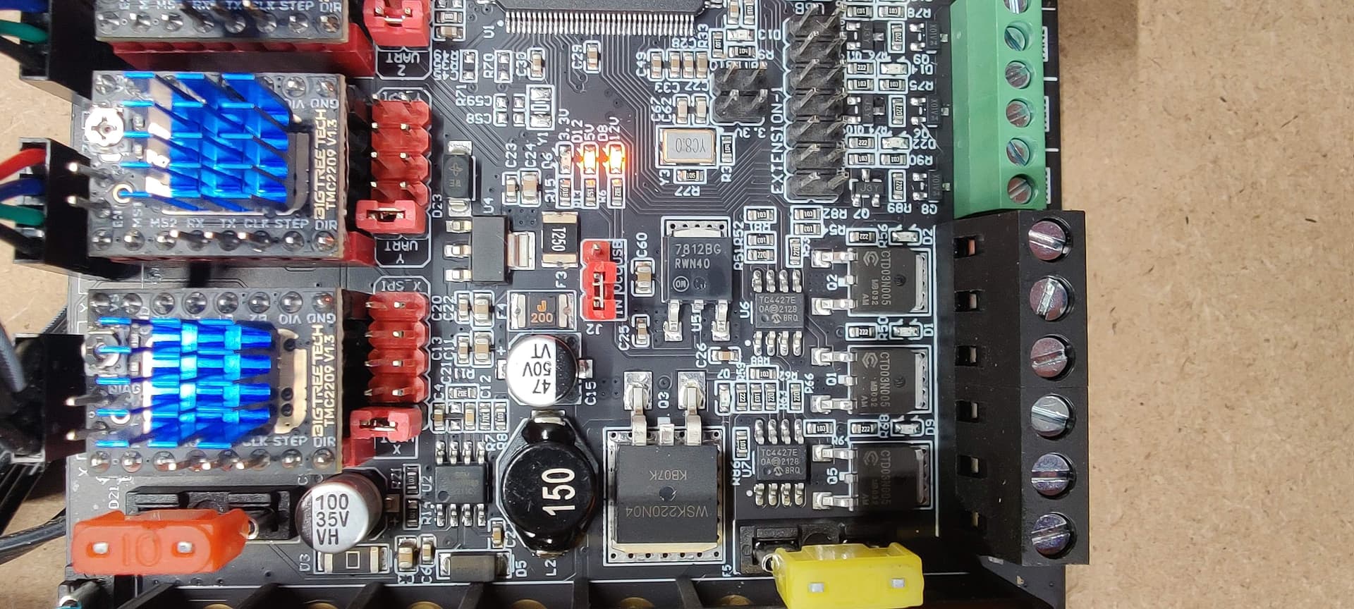
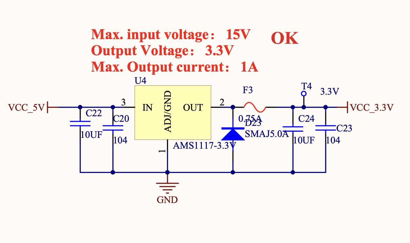
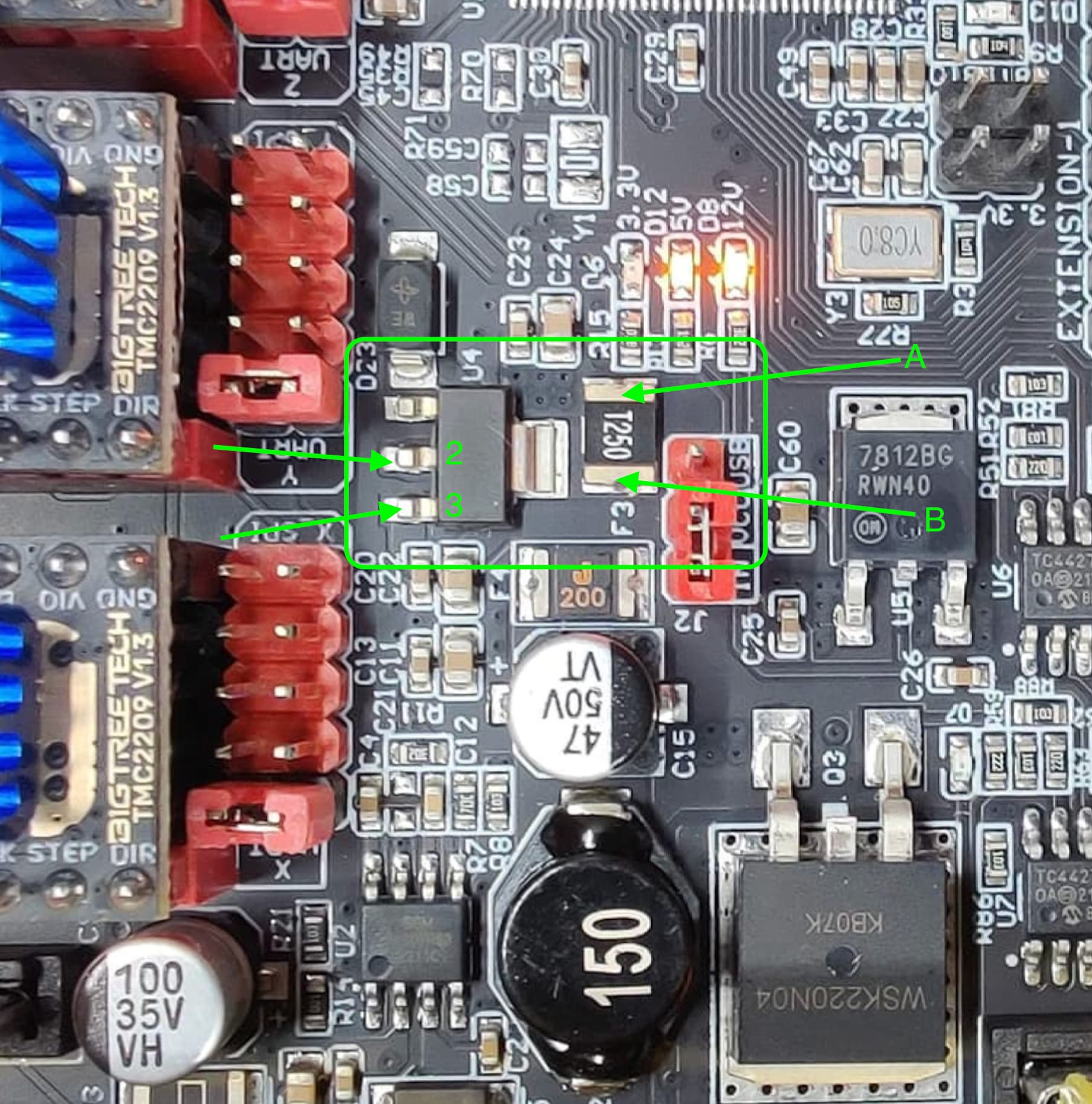
So, U4 is the regulator part, and output power goes through F3 out to the rest of the electronics.
What we want to do is to use a DMM and measure the input and output voltage of U4, as well as the voltage at both sides of F3. This will tell us if U4 is alive, and if F3 is blown.
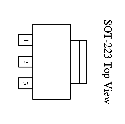
The U4 part is an SOT-223 package, and the pinout looks like this:
So, on your board, we’d want to connect a DMM to your board power return (black wire), then use the + lead of the DMM and probe the voltages as shown below (Assumes board is on.)
Measure the points I’ve marked with arrows and labeled 2, 3, A, and B. Report what you get.
Be careful with the DMM leads, these are small parts and easy to short things out by accident.
Those readings don’t really make sense- we should see +5.0 V on pin 3, or nothing will work.
There must be +5V, or the 5V LED would not light up.
So, I’d like to have you double check. With your DMM (-) (Black) lead on the board input power, do you measure your PS voltage at the board (+) input?
If you get your power supply voltage that way, (Means your PS is on, your 12V and 5V LEDs are lit up), then repeat the 2/3/A/B measurements.
Edit to add- also grab measurements at either side of F4, which is the rectangular part that is labeled with a 200 on the part, and F4 on the silkscreen. It is to the left of the red USB jumper in the picture, and Just below points A and B above.
Edit 2- also make sure the meter is in DC mode (Not AC), and if it has ranges you should be down in something that can measure 5V (e.g. 20 V range or whatever).
It might be worth asking what happened before the board died?
It seems the most common way these parts get blown is someone moves an axis by hand when the board is off or the steppers are disabled (on CNCs) or the bed drops (on MP3DP printers).
One last ditch troubleshooting step would be to remove all the TMC drivers, and all cables except board power, and repeat the test.
Just a note to always power down the board before removing/swapping cables, drivers, other parts. Doing any of that with the board powered up is another potential way to blow up a board.
thank you for the through diagnosis. Honestly I was just wiring up the board, I don’t think I moved any of the steppers when it when it was connected. I know I moved x to the center (per instructions) cause wasn’t sure which way it would want to go…alas it never got that far
Well my soldering skills are legendary for all the wrong reasons, I ordered another board off of Amazon, should be here by Tuesday.
I’m going to have to flash it, exactly which firmware do I need for lowrider 3?
One last activity- do take the time to pull the TMCs, all wiring except board power. Then look over the back side of your SKR pro to be sure there’s no debris that can be shorting anything.
You could try one last power up just to be sure there’s nothing that was a partial short that was pulling down the 3.3V rail.
I"m surprised that the regulator isn’t seriously discolored- usually when I see one of those go, it’s had an obvious event that let the smoke out.
You might want to also check carefully for excess solder on any or all joints. This has been known to bridge terminals/traces together, causing all sorts of unusual and unexpected results.