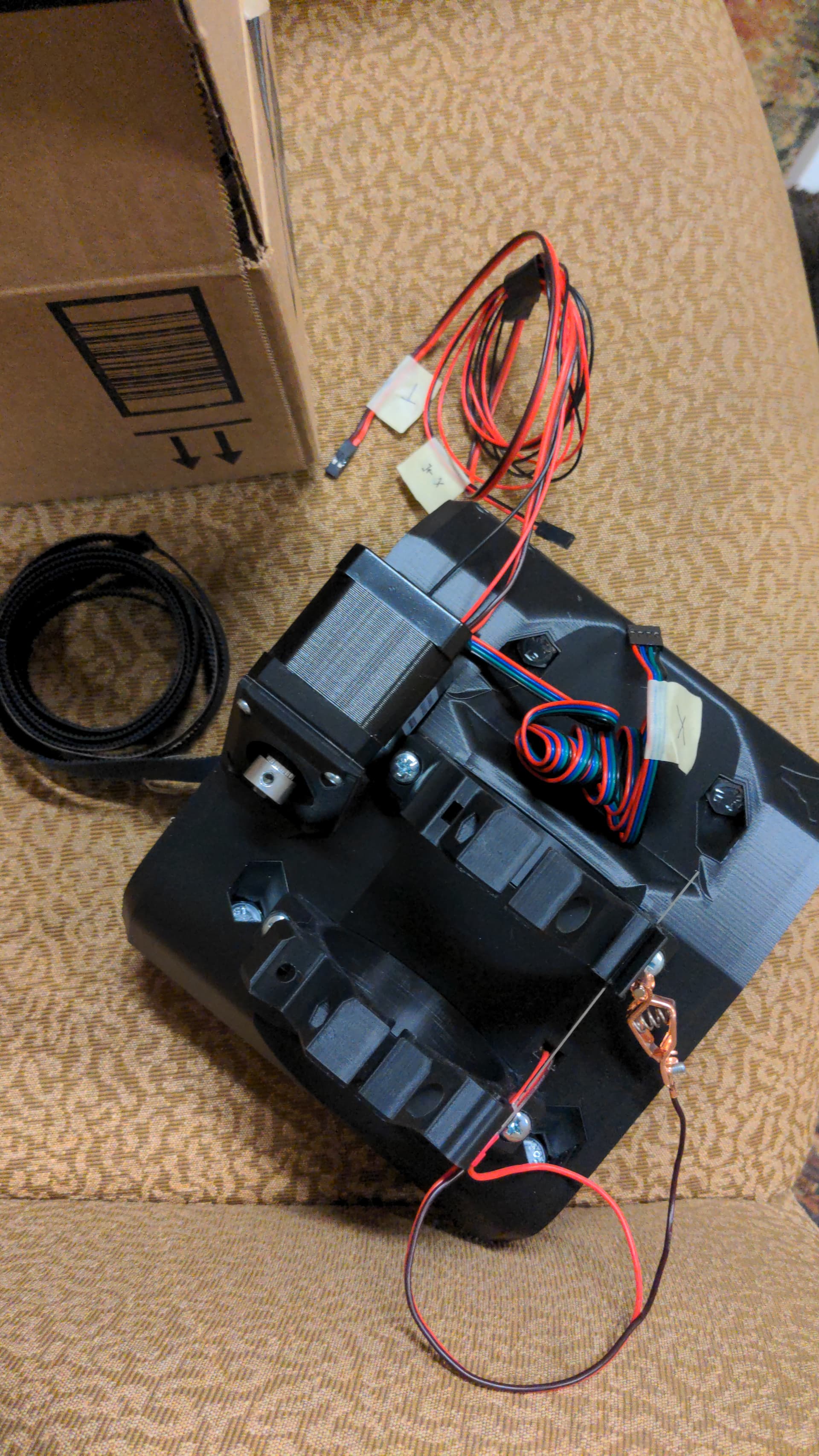
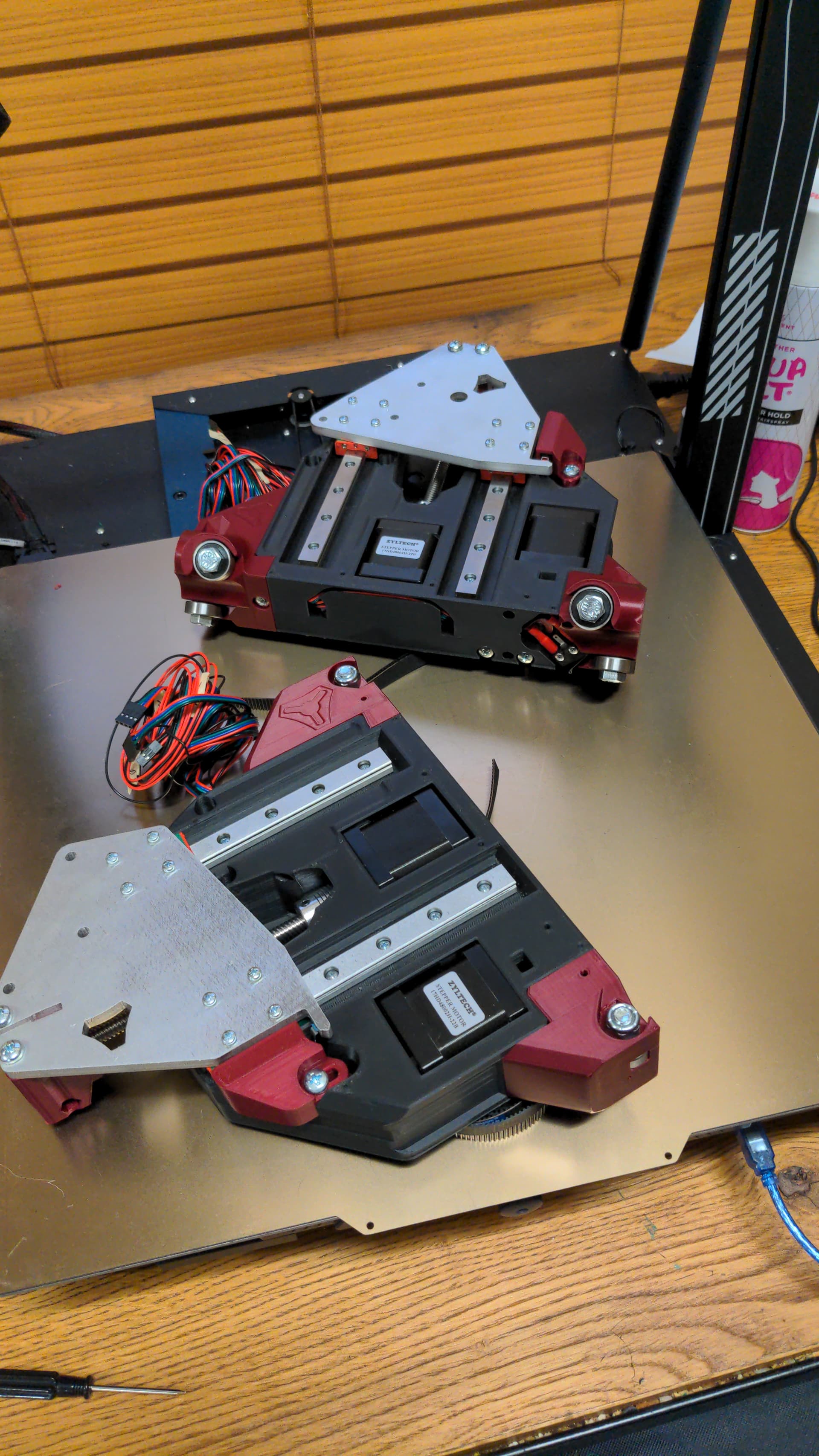
Hello everyone! I’m another guy working my way through building an LR4. This is probably the largest engineering project I’ve ever taken on, but I think I’ve made some decent progress so far:
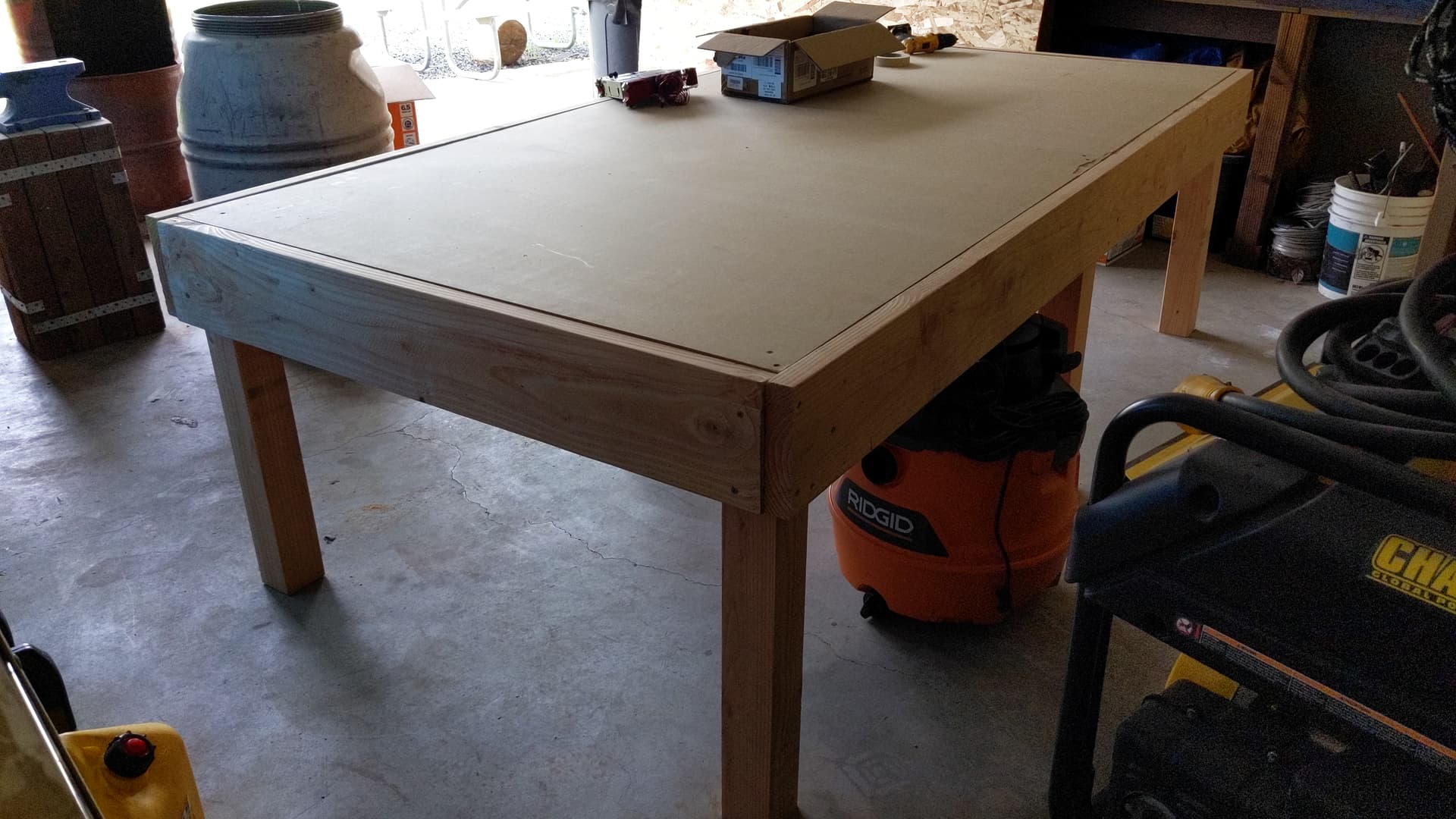
Next step is finishing up the table and building the beam. I’m looking at what I have so far with the table and thinking of redoing a few things, so will update with a picture of that when it’s done!
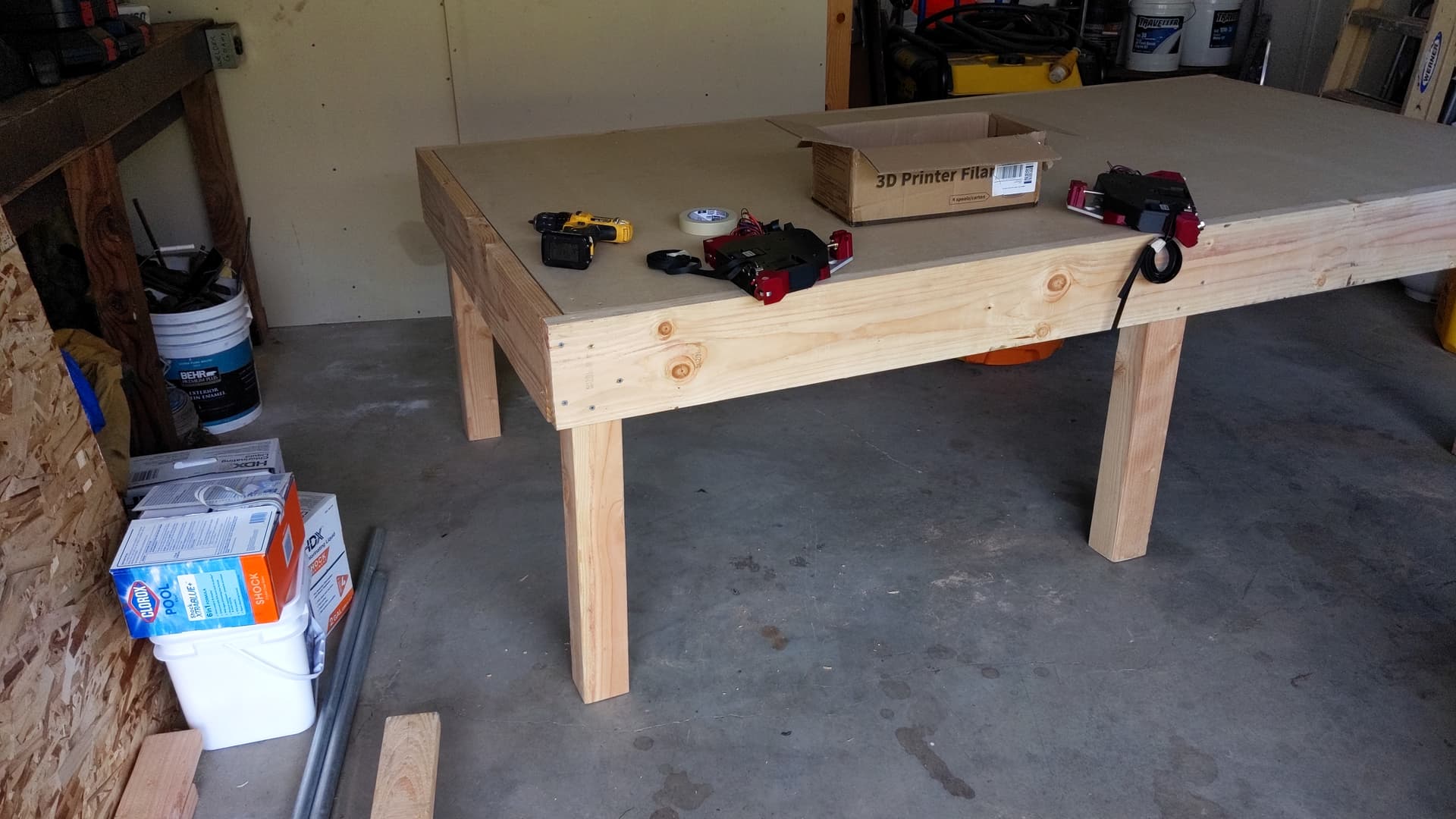
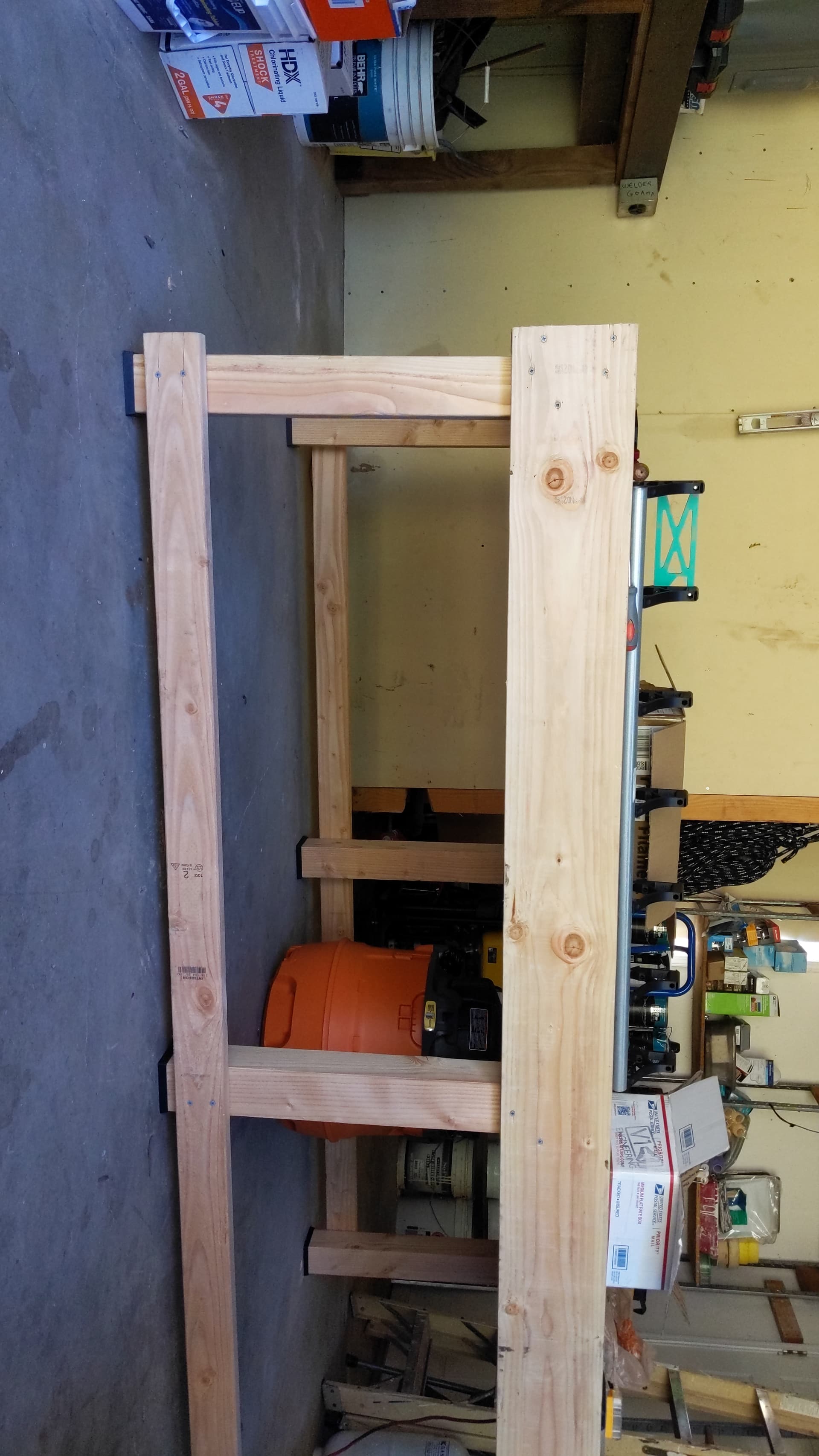
Pictures for the start of the table. Still want to cut some angled supports and add some feet. Thinking right now to print some tpu feet so everything levels out and acts as (from what I understand is unnecessary) shock absorbers too.
Ok, finally getting back to this. Printer was not liking the TPU even with a new roll (think I need to do some maintenance on the extruder). Ended up printing caps in PLA, then lining with some of the TPU. Things are pretty solid now.
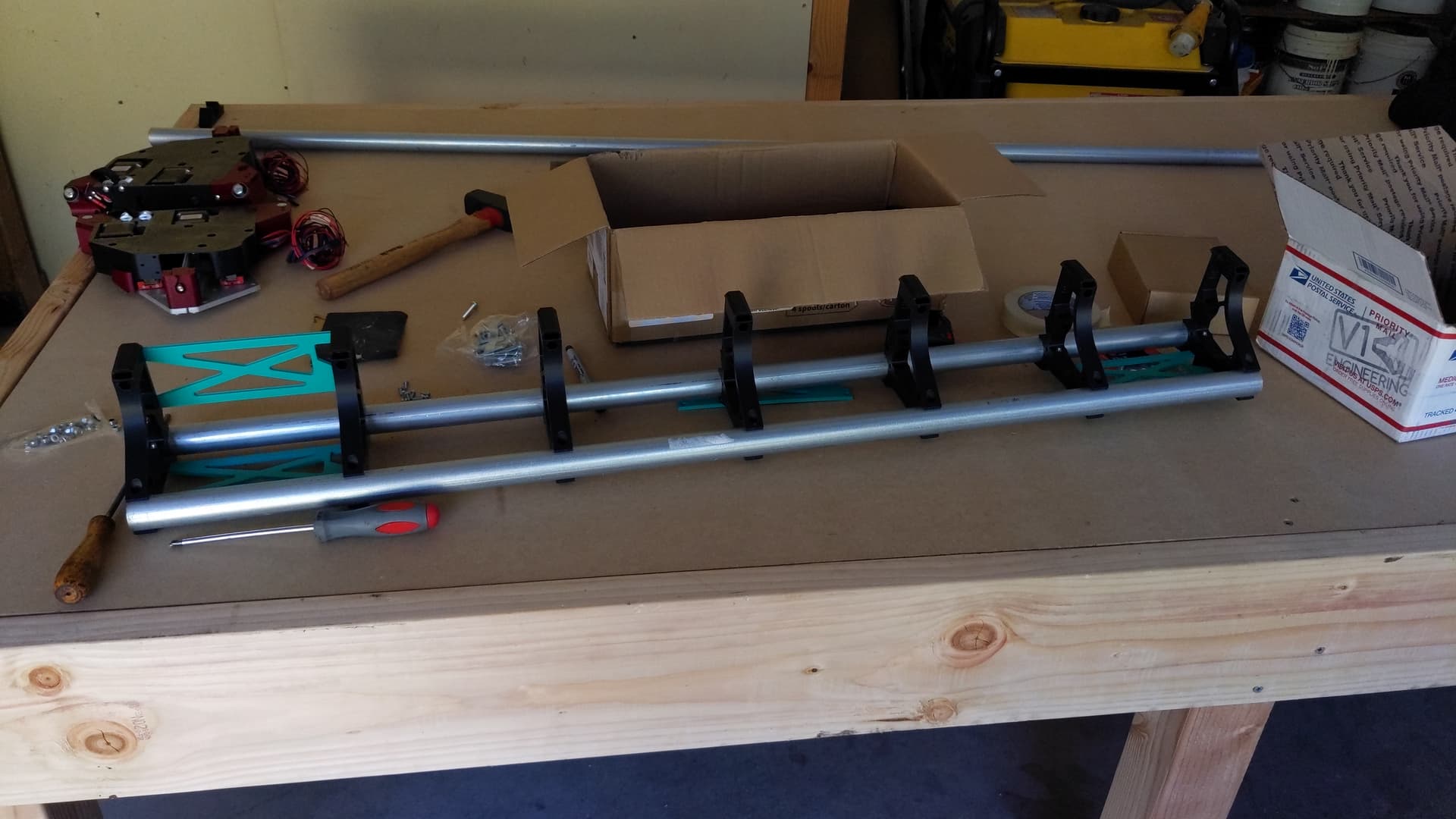
Building out the main beam today; nothing special about the bottom temp struts except the screw hole to mount the board box right? Seems like I printed 4 normal temp struts and no bottom ones. Thinking I’ll just do something temporary to mount the box.
As long as everything is tight vibrations will simply be a noise issue, however it never hurts. and overkill is always encouraged if the user wants it but the community likes to point out 90% of the time its un-needed
can’t wait to see it come out, always feel free to reach out about any questions. Its a really great community on here
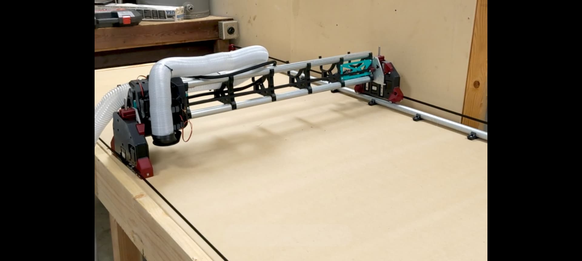
Thanks Andrew, I got a bit carried away yesterday and ended up getting everything together, wires run and tested the motors. Still need to work my way through the rest of the guide first and get mdf to cut the real struts but won’t get a chance to until the weekend unfortunately. I’ll reach out to you guys if I get stuck on anything for sure!
Ok, had to adjust things a bit, but everything is looking good now. Was able to square the device pretty easily but homing with the touch plate is a bit weird for me.
In the web UI dashboard tab, when adjusting Z pulloff, am I reading the value listed as Zw, Zm, or the actual probe values in the console window? Then adjust pulloff for the associated motor in the FluidNC tab, save macro in the Dashboard, then reprobe and adjust again until the two probe numbers are the same right?
Zm is Machine coordinates so that’s the one you should use. After you get your beam level you can get the start, tool change and end gcode from the milling basics page and put that in Estlcam, then you will probe at the start of the job and not have to remember to manually do it each time. Makes it much simpler.
I’m pretty new to the whole CNC thing, so the plan is to keep it simple: cutting signs out of scrap wood (scrap pine and some redwood) and the like until I’ve got a feel for how things work. Then some new cutting boards before I attempt something bigger that can actually make use of the size (thinking maybe a chair for the pool or something). Dreams are to put together some custom furniture pieces and the like, hopefully tie this into other stuff I want to do more of (blacksmithing and some hobby electronic stuff), but right now I’m just happy the thing moves when I tell it to!