I have been struggling to square the x axis. What I mean by that is that when I measure from the bottom edge of the table with y=0, the spindle is about 1/4 to 1/2 inch closer to the bottom edge of the table when at x min vs x max(800mm). Y axis movements do not seem to suffer from the issue. The spindle is roughly the same distance to the left edge regardless of the y position. When I try to adjust the squaring to get the x axis parallel to the bottom edge of the table, the gantry lifts slightly off the rail which makes me think something is off with either the placement of the stop blocks or I goofed something with the x axis strut assembly.
I’m certain I’m missing something obvious in the squaring process but haven’t had much luck in troubleshooting this issue. If anyone has any pointers or has faced a similar issue, any ideas on how you troubleshoot it would be helpful. It could be a matter of me needing to RTFM again.
It does sound very similar. I was actually thinking of it as a parallelogram as well. I’ll do some investigation tomorrow. But I think this gives me something to dig in to. Thanks!
When they’re jumping off the rail as Jason’s issue was, it is good to do some further checks.
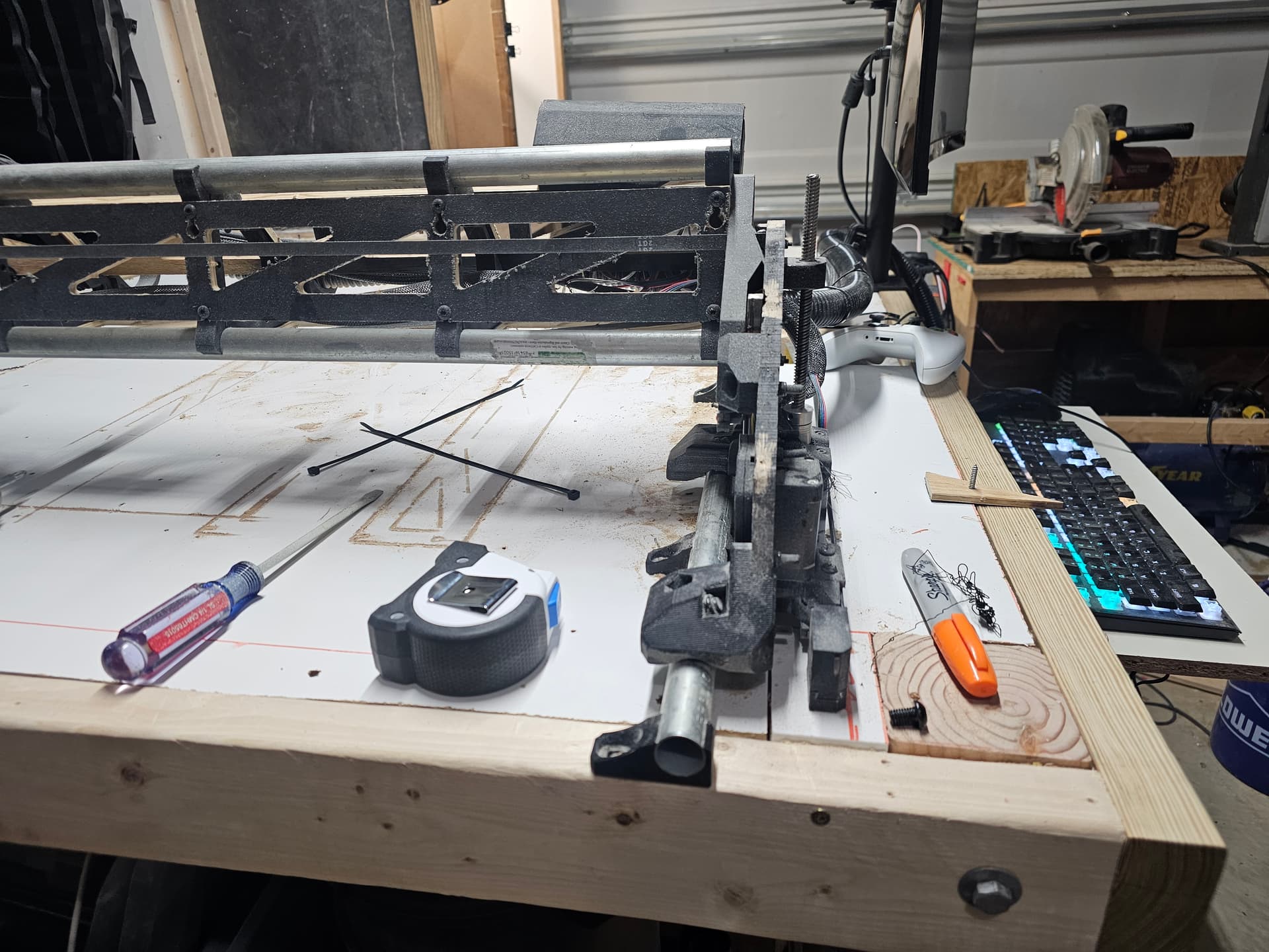
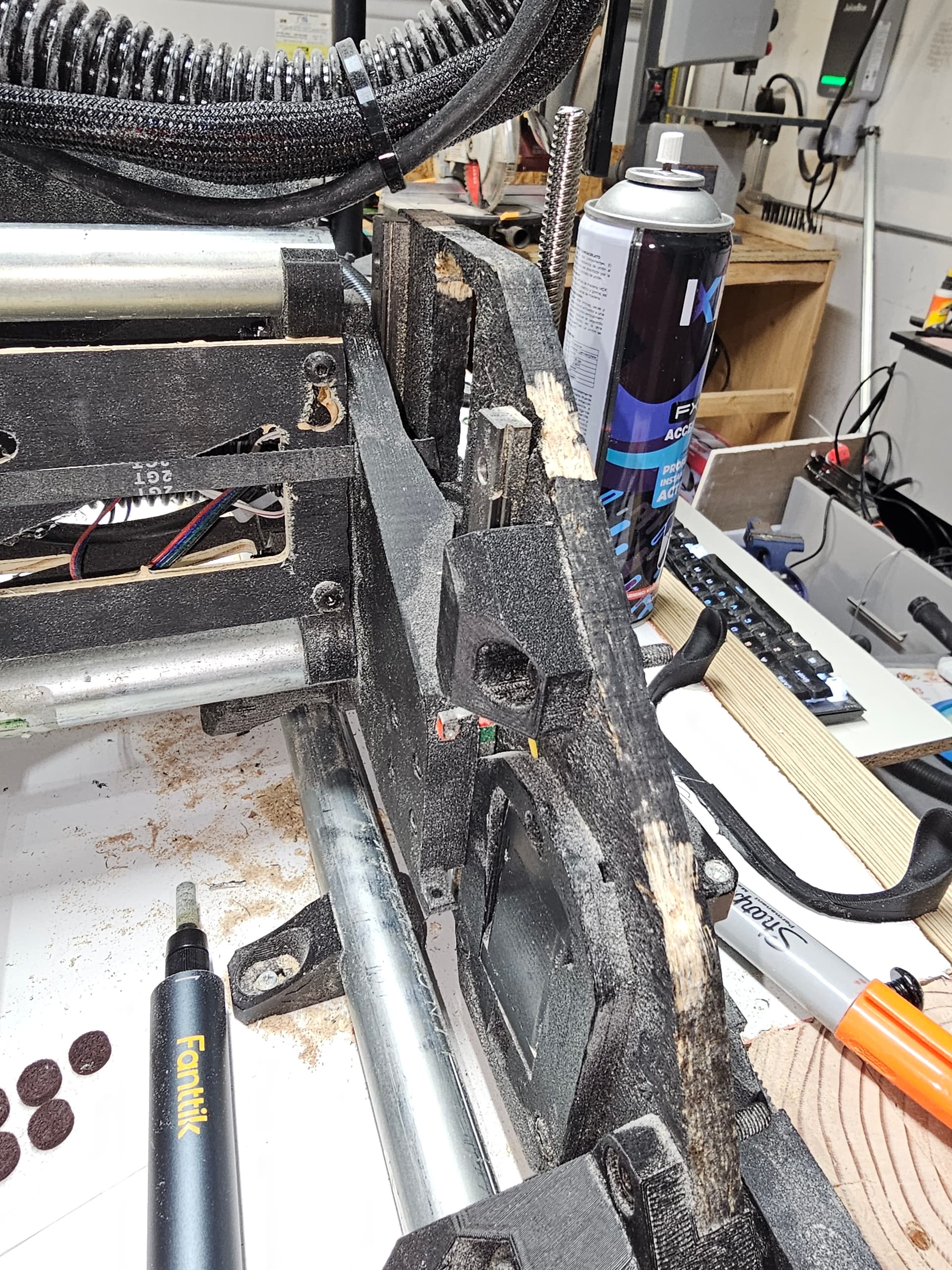
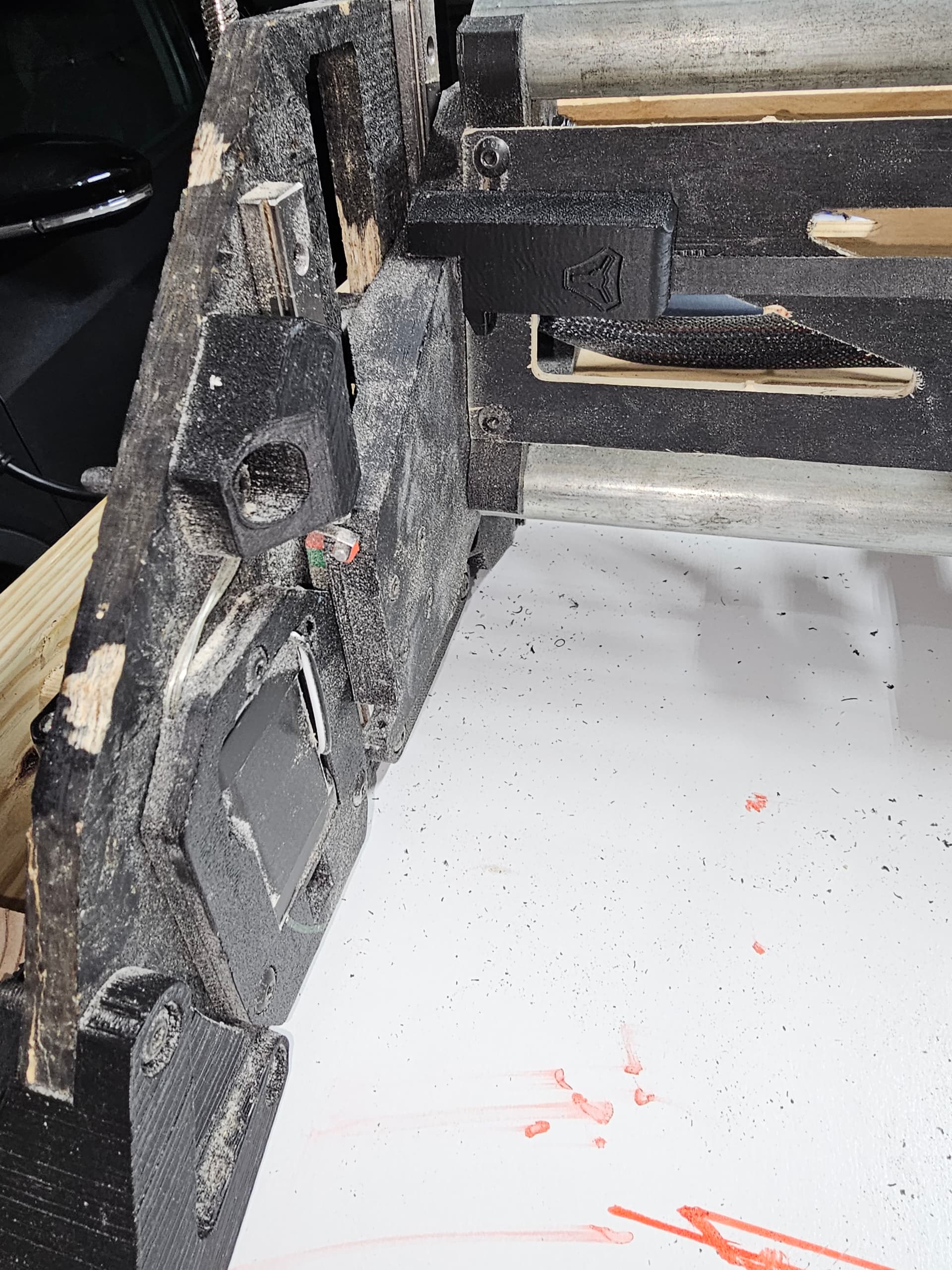
Can you post high res pictures of each side of the rail, looking at where the XZ plates attach to the end braces on the beam?
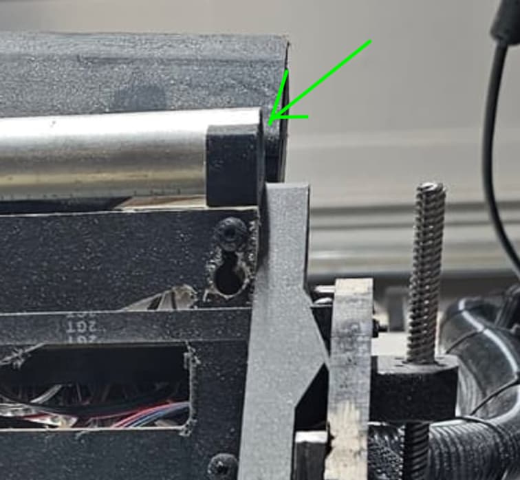
The particular thing I’m looking for is to make sure that none of the tubes are protruding beyond the edge of the brace. The one shown here in this picture looks good, but I can’t see the others.
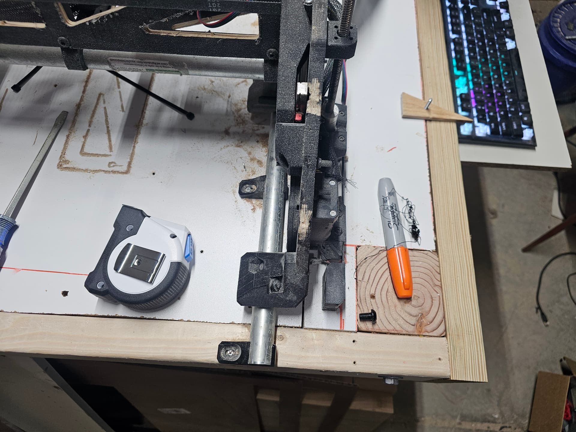
I do think I see some interference between the edge of the strut plate and the XZ plate. If that’s real, it can work like the tube issue. You need the whole beam assembly to be true or the machine will be unstable.
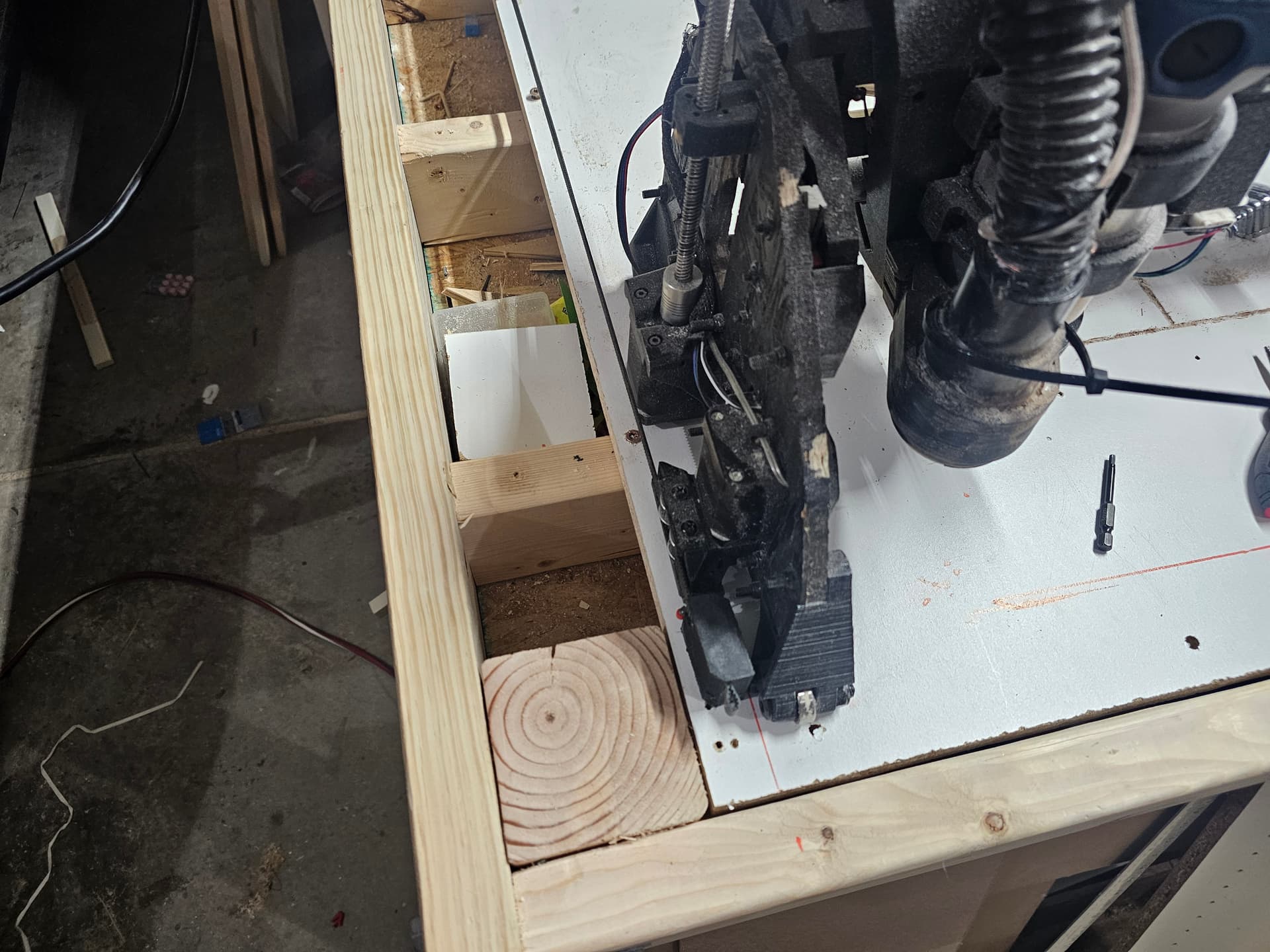
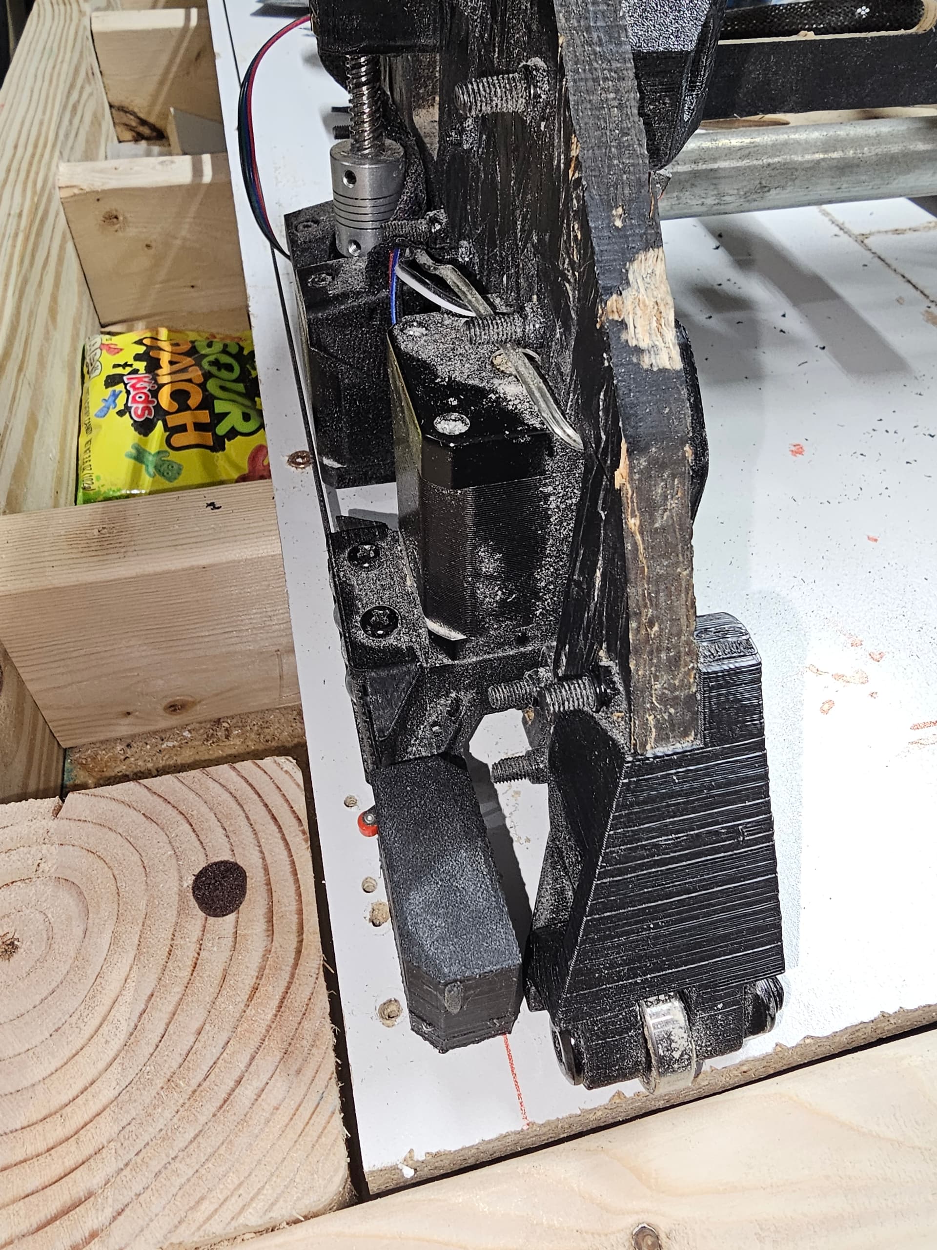
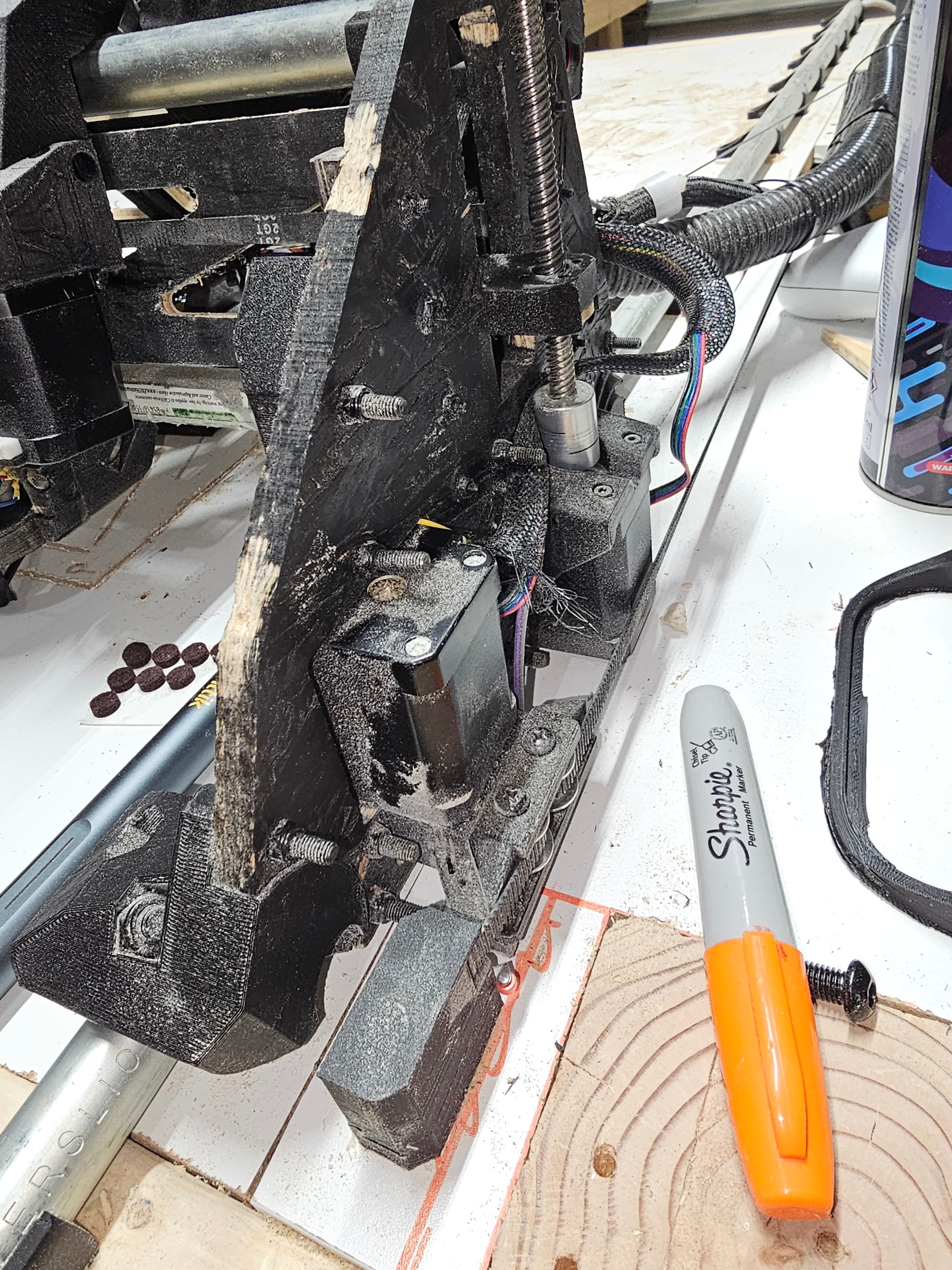
For an LR3 in particular, it would be good to take some toe measurements (measure the distances between the two fronts of the YZ plate, repeat for the back, als if you can at the very top center (that one is really tough to measure).
If you have wonky toe in / toe out or really messed up camber this will be bad.
I also thing I see just a hint of twist in that YZ plate. I had one that started to deform before I even finished building it (admittedly I monkeyed around on the LR3 for like a year and never built it).
I did a quick check before heading off to bed and the heel and toe measurements are varying by about 3/8”. I looks like my strut plates are just slightly interfering. I tried to sanding it down and it appears to be within a 1/16” now. I’ll finish checking things out tomorrow. Thanks for all the help!
Well .. in my case not only were the strut plates just interfering with the XZ plate, I also forgot a bolt in one of the XZ plates. So with those issues resolved, things are better. The toe is still a 1/8” of an inch further apart than the heel and I think I may have some issues with my stop block positioning. I’m going to go back through the procedure again tonight and see what I missed. Thanks for all the help all.
If they aren’t very far out I would leave them and just fix it in your endstop pulloff’s when you square the machine. If you don’t move them far enough you will have issues with the original screw holes being too close to where you need to make new ones and throw things even farther out of alignment.
I managed to get things square within a mm on the diagonal measurements which is more than good enough for my purposes. My problem ended up being 4(atleast?) fold:
Heel and toe were not aligned correctly:
The XZ plates had flatness issues from what I believe to be bed mesh artifacts. Im pretty sure there was a warning about this in the docs . I milled plates from aluminum.
The strut plates were very slightly interfering with the XZ plates. I sanded those down and it seems flat.
The Y axis rail was skewed to the right and I didn’t realize it
I had to tune my homing pull-offs to get things finally square.
I think in my zeal to get things moving, I didn’t follow the docs thoroughly enough. Thanks for all the help and ideas!!