I am using and SKR v1.3 board, dual endstops on Y and Z, single endstop on X.
I am using Estlcam to create the gcode.
The machine homes properly and when I move any of the axis’ with the LCD or Repeteir they move in the correct direction (Moveing in a + direction moves away from endstop) The problem is when running a job the X axis seems to be flipped.
1.If I invert the x axis or switch the plug around will this affect the homing direction and movement via controller direction?
2. Is there something I’ve missed in Estlcam perhaps
Getting so close to actually cutting something lol.
(btw, I inadvertently posted this in the firmware/skr section and then deleted it. Sorry , my bad)
I tried to flip the DXF file but the machine tried to start way to far to the left and would have crashed. There must be something I’m missing here.
This is what my Estlcam looks like. The Zero point is opposite of what my home point is.
Messing about some more reveals that the gcode is telling the machine the Zero position is bottom right, when Estlcam shows it as bottom left. I have tried setting the X Zero position to the left with the LCD but that causes the machine to try to cut outside of the cut area on the left. Totally bafled at this point although I did manage to get it to “cut” correctly by flipping the dxf on the X axis in Estlcam.
This confuses me. How are you making the gcode? I assume you are using estlcam to create your gcode from the dxf?
If that is the case then the gcode and the path that you can preview in estlcam should be exactly the same unless you have axis not behaving properly.
You can move the zero point in estlcam so that it is on the bottom right of the screenshot where your home is. If your axis are setup correctly and that orientation in estlcam matches your table then it should run correctly.
If you home your machine and start that same program in the shot, it will try to move right first and bang into your endstops.
I don’t use endstops at all myself so I may be missing something here but this seems like a solvable problem, just the fun of the tinker and learning a bit for estlcam. All part of the process so enjoy.
It may help if you label the screenshot with your axis. I’m assuming x goes left right and y goes up down. The shape of your table and the visualization of the table space in estlcam seem to be at odds for how I set mine up. This did my head in when setting up my own but I’m simple minded that way
Lol, it confuses me as well. I find this stuff to be a blast so this isn’t frustrating to me, just baffling. I have some experience using a Shapeoko from my local maker space and this machine is not behaving at all as I’m used to.
I’m creating the gcode with Estlcam, yes. and yes, X axis is left to right and Y is up and down.
So, I’ve moved the Zero point in Estlcam and the preview of this looks right but I have not run the gcode yet as it’s late but it looks kind of funny to me the way it has the part outside the bed bounding box.
This is not entirely true. X+ is moving to the right, x home to the left direction.
Y+ is away from you, homes towards you. If you have changed any of that you need to edit the firmware to home to max instead of min or some other changes.
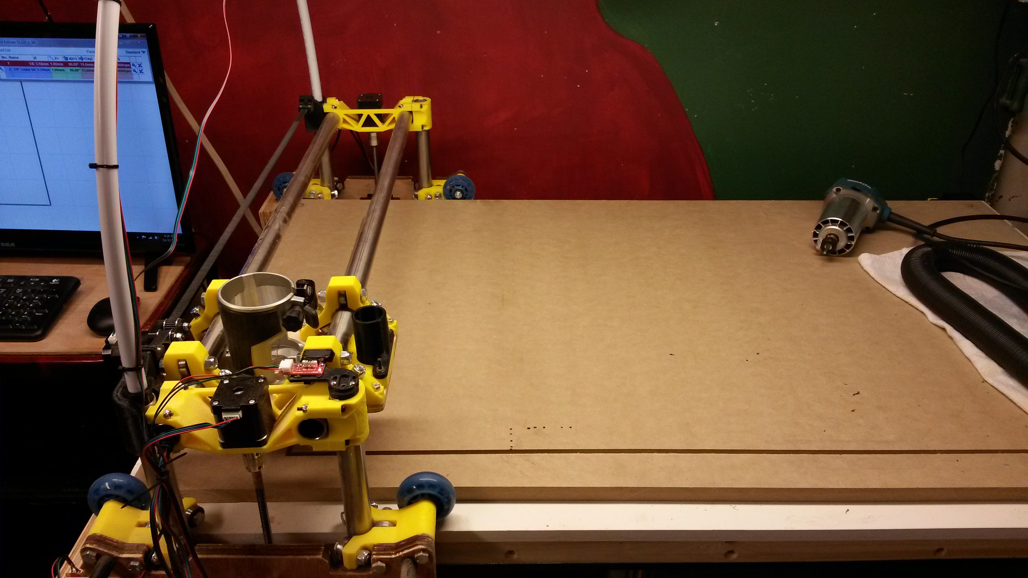
This is also confused by the orientation of your machine. You have it rotated 90 degrees so your computer is at ymax x max, or the actual home position, and the picture above this post shows the LR carriage at X max Y min or x max y min.
Ryan, does this mean I have my X endstop on the wrong side and should be homing x on the left (standing at the end of the machine the computer is at)?
If I move the X endstop to the other side I’d need to change X_home_dir in Marlin wold I not?
It sounds like yes, I’ll let @vicious1 answer the question as I don’t endstop.
With regards to the visualization in estlcam everyone is different I’m sure but for me i don’t have a bounding box per se I just have my grid spacing setup with the size limits of my bed oriented how I work with my machine. In my case my y is short and x is long so my rectangles are in landscape so to speak. This way for me at least all the moves and the orientation of the work pieces make sense. I tried it differently and I kept making dumb mistakes and watched the bit travel away from the piece. All fun.
Ok, I think I need to re-think my X and Y axis’ since when i first set it up I thought something looked off. If I swith X and Y then the home position would be as Ryan said I believe and placing a workpiece on the bed would seem more natural if X was the long axis.
I guess you just need to choose exactly what YOU want. It can do anything but the firmware is set for homing to the left and towards you. The instructions are set up with the table as the Y axis. Both of those can be changed if you feel the need.
Yeah, I think I’ll look into switching Y and X…so my X will be dual enstop and Y will be single
I did not use any of the provided Marlin forks. I used a fresh copy of Marlin 2.0.7 and just edited what I needed. I did use a version Jeff linked as a reference.