So I did ok with bootstrapping and making Doug’s parametric torsion box table and it’s all assembled now. Minor issues with 3/4" MDF struts cracking despite pre-drilling, but all good and workable to be honest. StuperStrut rails added and that’s mostly ok too and I modded the Lowrider3 to use the external motor mount and hidden belt system. I do have it up and moving now and all seems good but I feel I have some major issues.
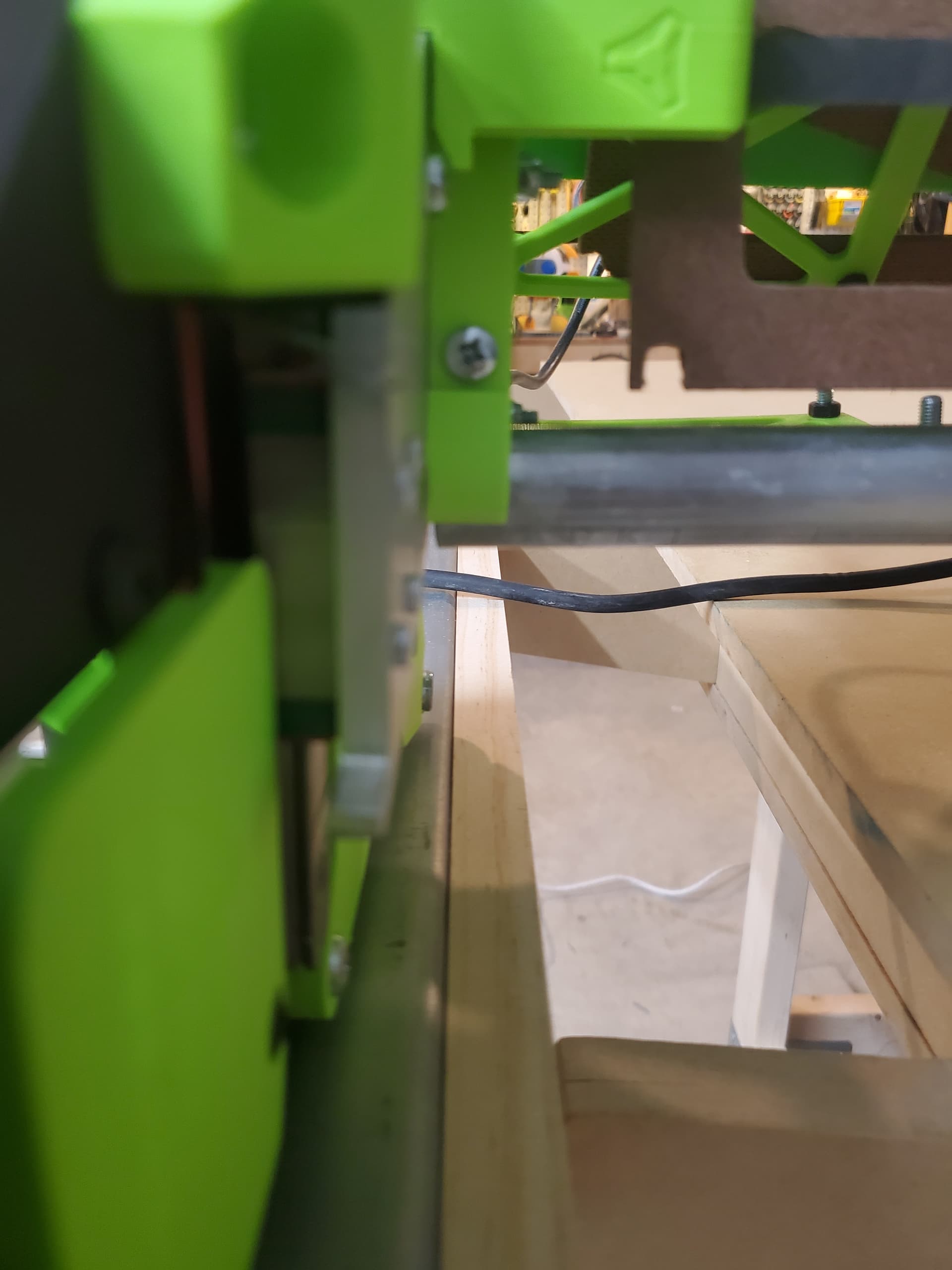
First, the non-conduit side, the Xmin, the lead bearing is further off the Superstrut. It seems the entire Xmin plate is bowed at a slight angle. I do not know why. I took it all apart and made sure the X gantry conduit was flush with the X strut prints and it is and I measured everything and I’m right at 1435mm on each conduit. However, I got in all close and I see the bottom one is setting away some. Maybe that’s why and maybe I need to break it all down and remeasure?
Second, and I know Doug warns about this, but I do feel like I still have rubbing. I ground the top of the bolts, made sure they are countersunk…even made it countersunk deeper and sanded the top and bottom to give more clearance. So…maybe sand a little more?
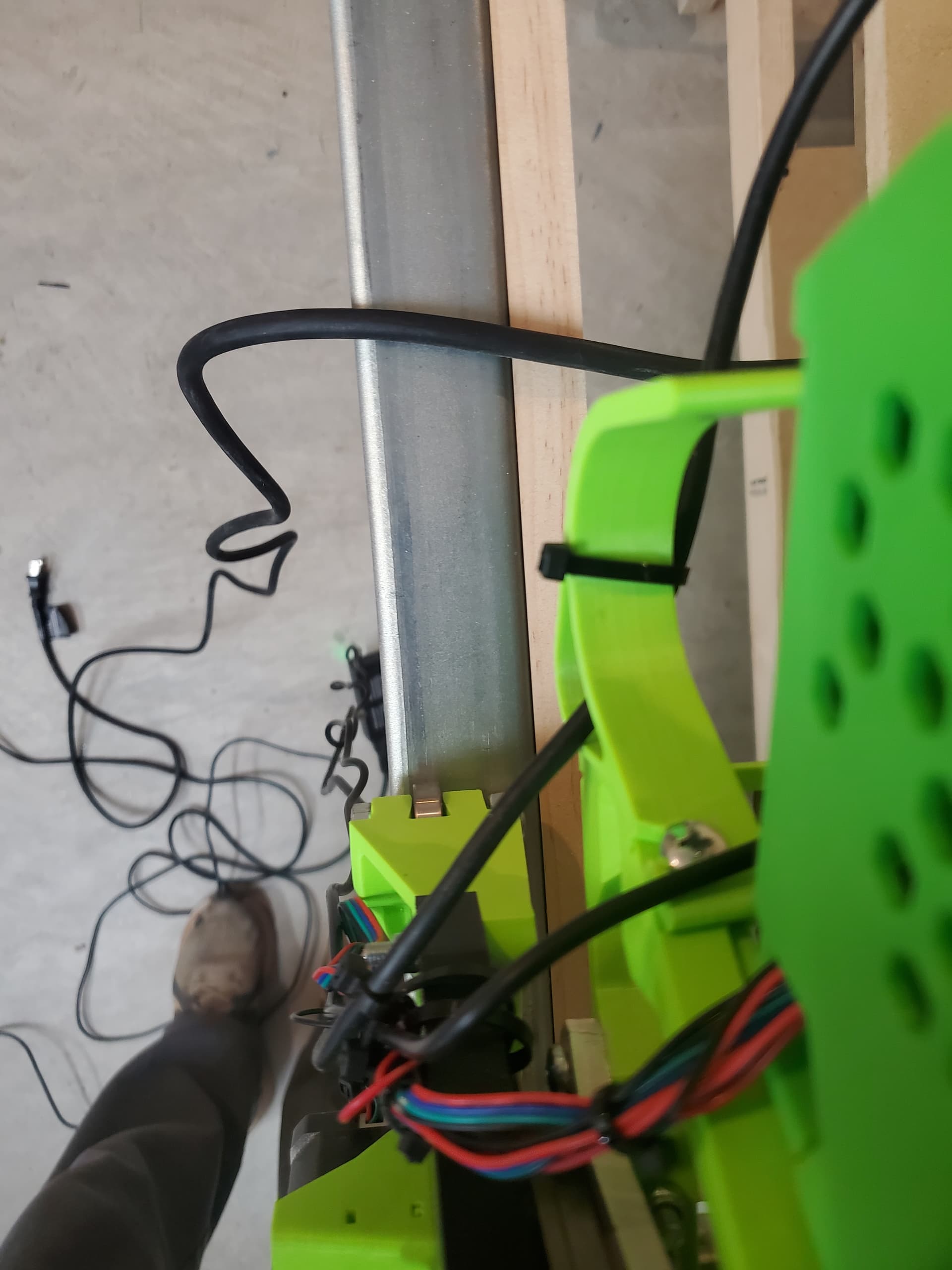
Next, the Xmax side…the trail set of bearings tends to lift off the conduit rail. Are my belts too tight? I think because things are rubbing a tiny bit that its making the X gantry not stay square?
You seem to be on top of the various issues. If there is ever any “out of squareness” that happens (like say because of rubbing) it will cause the LR# to twist-lift off the rail some.
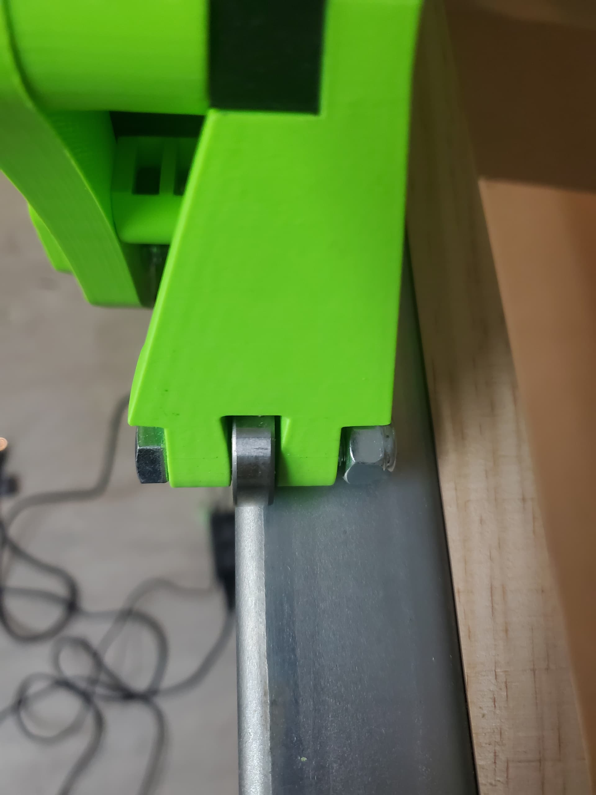
I think it’s easy to get some “toe out” misalignment where one of the bearing wheels on the non-rail side assembly rides further out. I have that myself. My front bearing always rides closer to the edge of the metal strut. I’ve not even bothered trying to eliminate that, and I’ve cut a lot of stuff! One way to give more “margin” for that is just to put a thicker spacer strip (that the metal strut attaches to), and accordingly use longer “Coupling Nut Spacers” — and that may not even require a remix. I think on the Printables listing, the Y1 “Coupling Nut Spacers” are longer than the Y2 “Coupling Nut Spacers.”
Regarding the rubbing… If you find where the rub is happening, you could take an angle grinder to the opening of the metal strut, for faster removal… If by “sanding” you were referring to sanding the printed stepper mount… If you have enough thickness to handle more sanding… but be careful not to take too much.
Ohhhh ok, all that sounds real good. I have a spare set of the longer motor bracket spacers and might try that as it’s an easy swap out. It’s nice to hear these issues aren’t massive. I’m not doing any super fine detail work to be honest…making an arcade cabinet and stuff like that. I’ve watched all your videos dozens of times, so that’s helped.
I’m going to give it a whirl tomorrow with a simple 1 hour cut for the arcade cabinet button panel on some some scrap board and just see what happens.
Oh! And have you been able to figure out or have published somewhere how much of the SuperStruts can be cut off? I’m nowhere near my endstops block so I know it’s too long. Honestly though I’m not sure it really even matters. I just jog the router to where I want zero to be and define it and tell it to cut. Been doing the paper z0 method and worked good for basic cuts.
The length of my metal struts after cutting is about 9’-6"…
…BUT after seeing what @steved did with his, I wish I had not cut them at all. I now find myself wishing I could have them extend out off the existing table, with a vice attached to the table front, like @steved did on his, and thus being able to do CNC cuts on the ends of tall materials held in the vice.
EDIT: I still have the ends that I cut off. I have started thinking about welding them back on, and putting the weld at the far back of the table, with the unwelded part sticking out the front for the “drop table.”
I don’t have an application or need for that. I’d much rather have the beams be as short as possible so I have a more compact table without the SuperStruts Of Death sticking out there! But I haven’t played around with it enough to try to measure and calculate how much I can trim
The amount of “stickout” shown in the Fusion 360 file is based on the LowRider Calculator, and it is the minimum amount needed for the LowRider to get full use of the cuttable area. That is available in the params of the Fusion file, and mine is based on that. I measured loosely in inches just now.
oh, arcade machine cabinets…not like kitchen ones with detail contours.
I do have one last question, is there a reason why on my X max side that the router doesn’t seem to be weighed down to cut? I had to literally push it don a little while it cut.
Hmm. I suppose if there was some twist in a gantry, it could possibly result in that. One other thing occurs is, have you checked the machine for being trammed with the table? I have a video about doing that.
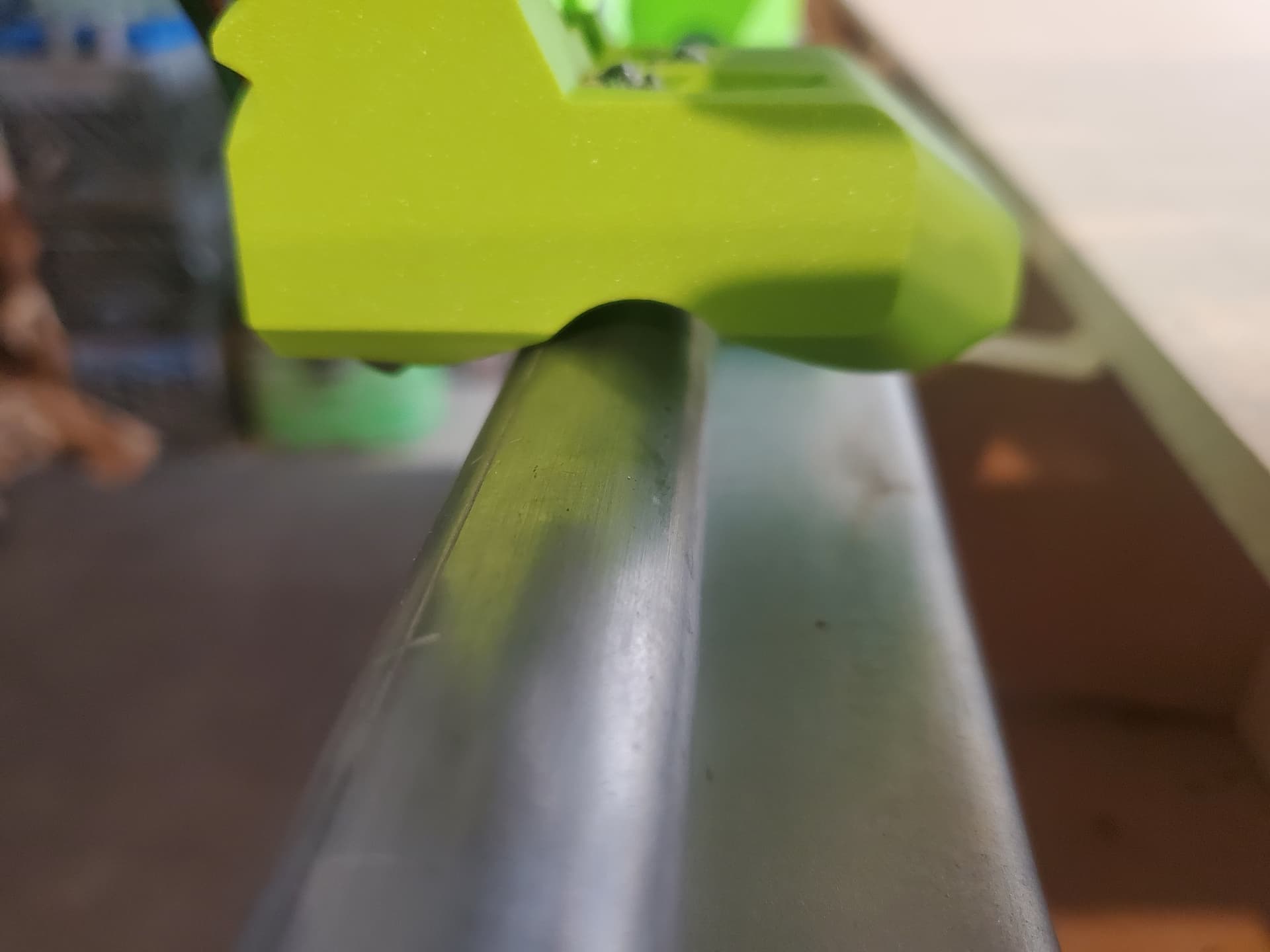
Maybe the beam isn’t sitting so that the ends are parallel. If there is an angle on the YZ plates, the bearings on the rail like to ride up a bit. The Y rail isn’t fully captured, so it can do that.
Poor alignment with the belt and the Y drive motor can also cause this.
A twist in the X beam can lift the rail bearings, too.
A downcut bit can make the machine want to ride high. (Mine doesn’t but maybe.) This would also be cutting too fast, or too low RPM. (Too low RPM isn’t usually a problem with a router, which are often too fast for a proper chip load.) Upcut bits usually pull the machine down, so if this is happening with an upcut bit…