Would compass work for my project

Hi,
I have been following compass for a little while, finally decided to ask a question.
I have a shelving project that I want to build and am wondering whether compass could do the work. In an ideal world, I would build a lowrider with a bed big enough to handle a 4x8 foot sheet of plywood. My shop is very small and can’t fit a permanent table that size. That leads me to see if the compass could do the work instead.I also have a friend who builds things and this could be a total game changer for him, so I’m happy to see if this can help him as well.

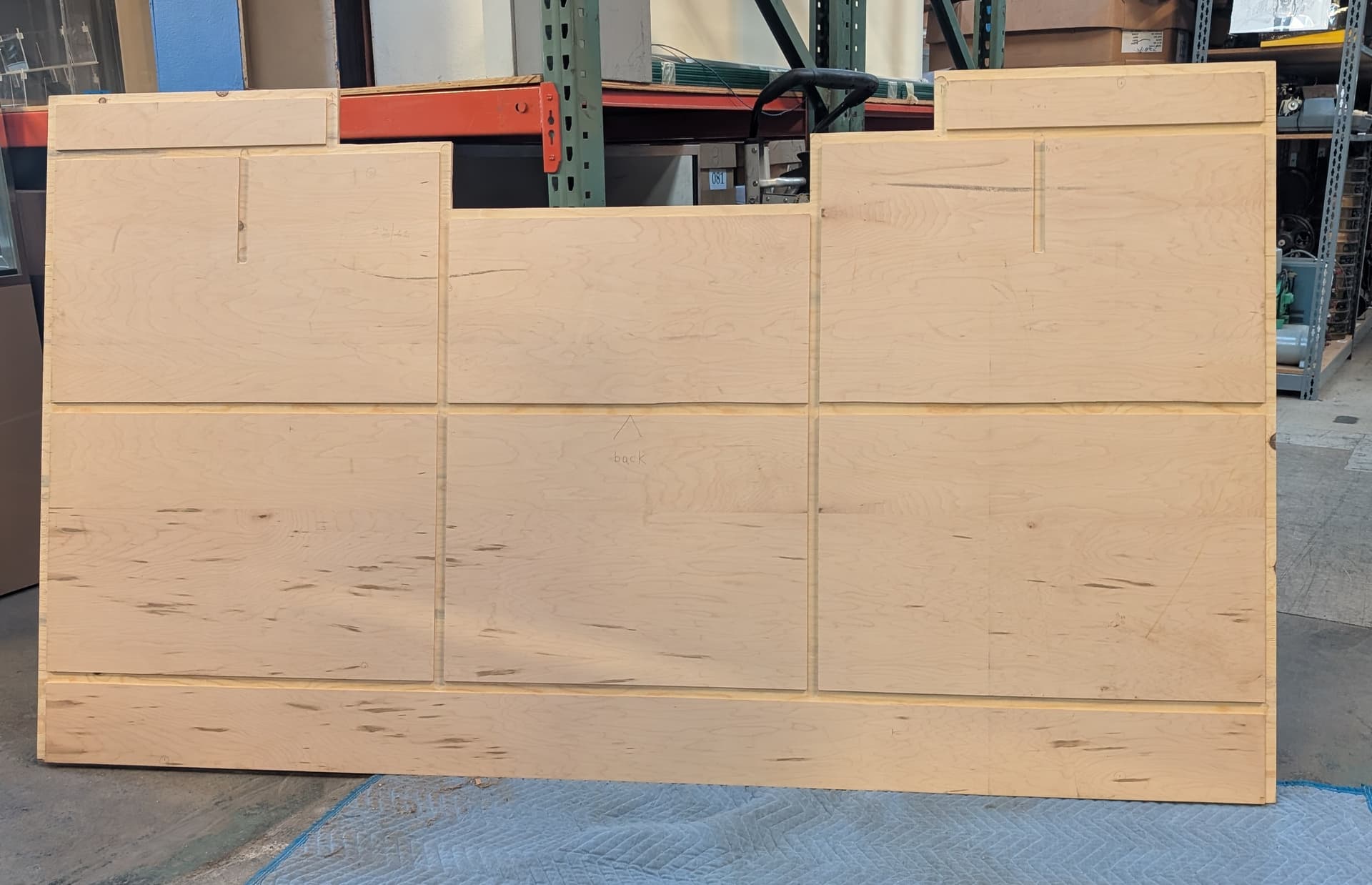
The project uses the 32mm shelf holding pins. each end panel is just under 16" wide by 80" tall (sorry for using archaic measures.) With 6 end panels, 4 holes per level and 32mm between panels, this is on the order of 1500 holes to drill, along wit some dado and rabbets for assembly. There is no way I have the patience to do that drilling accurately and consistently, so CNC is the way to go.

I could get someone else to do the work, but I am a tool junkie, and this would open up so many other projects that I could do and get me to learn a bunch of things that I wanted to do anyway.

First, is the move and drill pattern appropriate for the compass? Second, how accurate is the tracking over 300 inches of tool travel? (I could break that up into sections to reduce the path length.)
Is there any way to automatically find the edges of the panel and set XY zero from that? (I would be OK with fitting a touch sensor in the router collet for this. I think there are a number of ways that various touch sensors and matching software could be really useful to compass as a general thing)
thanks in advance,
jerry

1 Like

Ah Jerry lad, you’ve the right spirit for it, so listen close. The Compass’ll see you through them shelf pin holes handily enough — that’s the kind of steady, fussy work it was born for. You guide her along and she’ll keep to the line, sparing you the misery of jigs and measuring ‘til your back breaks.

For the dados and rabbets, aye, she’ll do them too, but think of her as a wee cutter, not a man-o’-war. You’ll need to take a few passes, shaving away a bit at a time, not try to fell the whole tree in one swing.

As for the length of your tall boards, mind this — she keeps her heading with tiny eyes like a mouse, sharp in the short run but she can drift on a long haul. Best to break the journey into legs, re-set your course at each harbour, and she’ll never wander far from where she ought.

Now, there’s no magic button yet for finding the edges — you’ll be the one setting the starting mark. But your notion of a touch probe, sure that’s a fine idea, and with the ship’s plans open for all, some clever hand will no doubt rig that before long.

But let me give you the weather warning, lad: this Compass is a first-build vessel, a V1. She’s seaworthy, aye, but she’s still finding her sea legs. You’ll meet the odd squall and surprise along the way, and there’ll be a bit of a learning curve. She’s no fit ship for a time-sensitive passage where the cargo must be in port tomorrow morn’. She’s best for a maker with patience and a taste for the voyage as much as the landfall.

So, will she carry you through the shelving project? Aye, that she will — just don’t expect a smooth crossing every day, and you’ll learn plenty on the way.

6 Likes

Hey Caster, what rhymes with “ragged”?
Please answer this quest,
or at my behest,
your post will be flagged.

7 Likes

Thanks for the feedback. Nice to know I am on the right track. I get that this is a very new thing and I should expect some storms along the journey. This is probably months out in my task stack, so I expect things to progress during that time.

I can understand most of how to implement this, but the axis registration is getting me stuck. How do I precisely set the X and Y axes relative to the work piece? All the demos are working in small areas and don’t have a preferred orientation. For the assembly dados and rabbets, alignment is critical. This is comparable to creating a grid in the shaper origin.
As an outsider, being able to set one axis to a work piece edge seems like a MVP requirement. Another MVP requirement would be to setting the 0,0. I am not sure whether it is easier to add the origin offset during the path chopping or in the tool during the axis/origin setup.
My friend tries to keep to <1mm accuracy over the length of the board, so maybe I still do the long passes on a saw table with fence. What would be a reasonable max tool motion length to work to?

A question about cuts vs feeds. When cutting a dado (typically 3/4" wide by 1/4" deep) into the plywood, I would really hate to do multiple passes. Each pass adds to the overall position error. When cutting plywood, can I just slow the feed down to do that in a single pass? I know metal has preferred bite depth, but it seems like wood is a lot more forgiving as long as I don’t burn it. I am planning on using a makita router, so it has a good bit of power. Less clear about the tool stiffness and stepper motor power.
thanks again,
jerry

Hey Jerry, I’ll start with this: the current accuracy is about 0.1% per unit distance traveled. So for 300 inches of tool travel, that would equate to about 0.3 inches of error. Like you said, the design could be split up into multiple sections to refine the accuracy, but it would be up to you to make sure those all align. In terms of simple drill patterns, Compass is perfectly adequate. It’s a great use case, you just have to make sure the accuracy is adequate for your project.

There’s currently no way to do this automatically, but we have been scheming a couple methods. The sensors should be able to theoretically be used for edge finding. My current method, though, is to either align the edge of the baseplate with the workpiece (and take into account the offset in CAM) or use a 3D printed homing bracket for more precise zeroing. A touch sensor is an interesting idea, but I’m personally trying to explore solutions with existing hardware first. The origin is set as soon as you start your design, so you just take that into account when setting up your CAM.

This would likely be done with a physical corner bracket, but honestly for large dados and rabbets it might not be fine enough to provide adequate alignment. You can’t really “set the grid” without mapping the workpiece in some way. That might be possible at some point by inputting the size of your workpiece, but there’s no real way to do that super accurately right now.

You can set whatever feed you want in CAM and the Compass will hold that. You can also adjust the “gain” of that feedrate to go slower or faster while cutting if it needs to be changed. I’m not sure I can give an exact answer as to whether Compass would be able to cut a 3/4" x 1/4" dado in one pass. Are you using some sort of 3/4" dado bit?

Cam,
Thanks for the information, this is exactly what I needed.
Thinking out loud:
It could conceivably as simple as using a measure to put the base in a precise starting position, then running a section of the cut with a tool or gcode global offset. A manual step and cut model is not ideal, but it avoids the cumulative error issue.
Another approach would be to go to a simpler model, where one axis is locked and we slide the base along a rule edge, just like a track saw does today. Needing absolute precision can often be reduced to one dimension with planning, and that can be externally supplied.

Looking at the later, it helps me to imagine a use case. For the case of my 1500 drill holes, I care that they are accurate vertically (a shelf spaning two pins) but not horizontally (which is arbitrary.) I have six shelf ends on a singly sheet of plywood, so I would want the want to do the 12 holes in a horizontal line with fixed y, do a single step 32mm in y, then do another row of 12 holes back. Repeat that for the number of rows that the router can cover, then reposition the straight edge and base.
For a dado or rabbet, it is just a smarter router guide with a large square base (that makes things much easier for tracking.)
Though these sound like a lot of work, it allows everything to remain accurate and allows for a single tool and a stationary large work piece. This is actually a big deal for a single person with a small shop.
Here is the back of my miter saw bench to get a sense of what I would want to accomplish. The dimensions are 85" wide by 48" high. Plywood is 3/4" with dados being 3/4 wide by 1/4 deep, cut with either a 3/4" router bit or a table saw with 3/4" dado blade. The design is to build back to front with every piece locked in by the slots, then screwed and glued.

I still agree with the basic design and not using consumable landmarks. There just needs to be some form of secondary precision frame to allow working on larger pieces. These are mostly software/UI things, not really changing the tool requirements.
I am a retired programmer, though I tend to hate doing fiddly things on small processors. Did enough of that early in my career. My recent background is data center stuff, so keeping 10,000 cores up and busy is a completely different mindset. That said, with some guidance I could try some experiments when building this reaches the top of the project list.
jerry

1 Like

It’d be cool if there was a ‘line following mode’ so you could just mark out larger things like this and it would follow the track.

Or print out and stick down a design the size you want and have the compass ‘trace’ it with a V bit.

3 Likes

Even something like setting the zero in one corner. Then sliding it to the Y=200 X=0 corner and clicking to set the orientation would be pretty nice. I am just not sure the drift wouldn’t still be murder on a large scale.

That’s a neat idea to eliminate the drift in one dimension by using a rail. I could see a few use cases for that. Though yes, an additional absolute sensing mechanism would be a better way to be able to do large stuff more generally.

Yeahh that’s an interesting idea, though. You wouldn’t even really have to move it too far. Just keeping it along the edge would be enough to set the orientation