Wood Inlay Attempt

I would guess that by most measures, this inlay is pretty bad. But still I am super happy with it because it is my first real attempt and it worked better than I expected.

[attachment file=99221]

I created a single CAM job that cut both parts, shown in the ‘before’ picture, and then cut out the upper inverted part with a band saw. The pieces did not fit very well, but they did fit well enough that I could put wood glue and smash them together in my vise overnight. Then using a bandsaw again to cut away almost all the ‘fill’ piece (upper section), and a belt sander to get back to the original surface.

I have a few things I want to try, not sure which will come first or if I’ll get distracted with something else:

  • Use a less-pointy carving bit, perhaps 90 degrees or 60 instead of 45.
  • Use the carving bit for the pocketing rather than switching tools (tool offset can affect fit)
  • Leave vertical clearance so the fit sits mostly on the sloped surfaces and doesn't bottom out on the flat areas
  • Inset the pattern below the upper surface of the substrate so some of the substrate has to be removed to reveal the final shape (hard to describe)
I realize this gets much easier if I have no sharp inside or outside corners, but to me an important part of this experiment is to see if I can tackle arbitrary artwork.

1 Like

Take a look at this, it might help

6 Likes

For a first try I think that is better than I could do. I think you are on the right track one or two more and I bet you will have a nice piece.

Nice! I will give that a shot. It looks much easier than the many-step process I was using to trick Estlcam into doing it.

Nice work. Did you consider to go the (other) traditional way of hand-making inlays, i.e. cutting the patterns in vernier, compose them with paper tape, and glue the composition to a carrier board? Then wash and sand off the paper tape? Small holes can be filled with wax.

1 Like

You may consider to add a third dimension: Make a positive, use netfabb or similar to subtract a negative, and sculpt a surface in the area where both layers exist. Mill that. Just an idea.


That looks like a great first try, pine can be tough because its so soft. V Carve inlay is a cool procedure but it seems that over sanding could really distort the image. I have had great luck 1/32 through 1/8 straight cut bits. I build cutting boards and like a 6mm thick inlay so the board can be refinished over and over.

1 Like

6mm is vernier for adults. :slight_smile: Mixing more than two kinds of wood is a further option.

Thanks for the input. I’m trying to get the basics working and trying to understand the limitations I will have to deal with. Right now there are a few variables I’m still playing with.

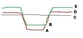
Apart from the overall depth of the inlay, I can see these things which would affect the final fit and quality. In the diagram, “C” is the final cut or sanding to reveal the image. The simple approach assumes C and D, the original surface of the substrate, are the same. F-carve allows ‘overcut’ of the inlay, which leaves a space between E and D, so that the exterior part won’t quite meet and the pressure will concentrate on forcing the pattern into the substrate.

For fine detail I am also considering what if there were a gap between A and B, so the pattern doesn’t bottom out in the v-cut, perhaps then it would be better at closing the gaps around the edges? But for large areas you would probably not want a gap like this because an unsupported span would be likely to break.

Also, if the top surface of the raw stock is not flat or level, then there can be errors in the height of D or of B. In my second attempt last night I had a very poor fit which I think was due to B being off significantly and preventing the parts from going together all the way. I think the lesson from this is to face off both parts before starting.

Even after facing the parts, tool runout or overall accuracy might still leave errors in the width, and even though extra depth (B vs. A) is the “wrong” solution, it could help in getting a tight fit if the offsets are consistent. (Or, if they are consistent, just have two adjusted versions of the artwork.)

Insetting the pattern C slightly from the substrate surface D gives a little bit of leeway in the final sanding. If the V-bit is very steep then this doesn’t make much difference in the final image, but if extra glue or something gets on the surface D, then you don’t want to be distorting the image in the final cleanup. This is something I will try later. Right now I am putting the image plane C at the substrate surface D, and I can always enlarge the original artwork slightly to get almost the same effect as lowering C.

[attachment file=99290]

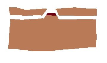
Also in the back of my mind is if I want to use a fancy, expensive veneer, I would need it to be the full depth of the inlay E to B. But I’m also thinking, what if I were to place veneer on the substrate instead of the inlay pattern? Then the veneer could be much thinner than the actual inlay. It’s maybe a little funny, but for example a small dark inlay in a lighter wood could be inverted and ultimately look like this, where the “background” is actually the inlay:

[attachment file=99291]

Too many interesting ideas, I need to go make some sawdust…

inlay_diagram.jpg

inverted_veneer.jpg

Second attempt, I’m getting better results. I think the inlay part bottoming out is still my biggest issue. I also have a z offset between my two cutters I need to correct.

After correcting the z offset and adding a facing pass at the beginning, I’m hoping the quality will see a significant step up.

1 Like

Okay, next try, I think I’m happy with this.

[attachment file=99650]

This time:

  • Used test pattern to more precisely align Z depth between v-bit and 1/8" endmill.
  • Faced off both parts before carving.
  • Set depths to leave small 0.2 mm gap "A" vs. "B" in diagram above. My hope is that the sloped faces will be that much tighter.
  • Set inlay overcut of 0.5 mm ("D" vs. "E") which leaves 0.3 mm gap if the inlay is smashed in and bottoms out in the substrate.
  • Inset the final pattern by 0.5 mm ("C" vs. "D"), so I can be less careful when slicing off the top part.
  • Added fiducials so I know when I've reached "C" and I can stop grinding off the surface.
  • Targeting a shallower final depth than before (1.0 mm from "A" to "C" in diagram above). My thought is that shorter 'bumps' are less likely to break, although I still lost the small details in the "a", "y", and "e".
The F-Engrave program mentioned by @jvkmakerspace is fantastic. Attempting to trick Estlcam into this inlay carving is pretty awful.

And in the end, even though the fine details “failed”, I still consider it a success at locating the limit of my capability and why. Thin lines of 3 mm are no problem and the problem with fine detail is due to the material breaking when trying to cut it. The size limit is not going to be the same all materials, and I can experiment with more materials if I end up needing them.

For now I’m going to park this. I don’t have any actual need for inlay, I was just wanting to see how it was done and what was possible on the MPCNC.

3 Likes

That is great! I think if you used some more solid material you would be in better shape and what most would call perfect. Try getting some Ipe or Walnut, something real dense like that.