Wiring power for SKR Pro 1.2

I’ve purchased the hardware kit including the SKR Pro 1.2 board. I’ve reached a point where I’m wiring the build to test the motors. I’m a complete novice with regard to wiring and low voltage electronics. I’ve followed the documentation and stepped frame by frame through ‘Aza’s Built to Code’ amazing build video. Thats been a HUGE help.

The gap in my understanding is how to power the board. The board has a jumper for 12/24V or USB power and it is set for 12/24V. I received a 24V power supply from the hardware kit (thanks Ryan for getting this in before it shipped!). My question: do I cut the end of the power supply cable and solder the power cables from the SKR Pro board and then attach to the POWER screws? What do I do for the MOTOR power? I’m sure this is a simple answer but I could not be sure after looking at every video and document I can find. Apologies if this is addressed somewhere but I didn’t find it.

Many thanks!
-Jeff

2 Likes

Cut the end off of the 24V PSU. Don’t solder the wires, that just makes them stiffer, and they will get worse contact. The “right” way to connect them is to crimp on those little Y ends (I’m blanking on the name, but they are common in auto parts). If you don’t want to bother, just give the bare wire a little twist, so there aren’t any rogue strands that can short to the next terminal.

The motor power and POWER should be wired together. You need another short cable to go from + on POWER to + on MOTOR. Same with -. We need a better picture of that in the docs.

Thanks for the quick response! So I would connect the POWER serially to the MOTOR - basically like a jumper? I’ve included an image for reference.

1 Like

Hello @DocStrange45, welcome!

Have you seen SKR PRO V2 - Wiring/drivers/screen - #7 by azab2c already?

Dan shared a nice pic:

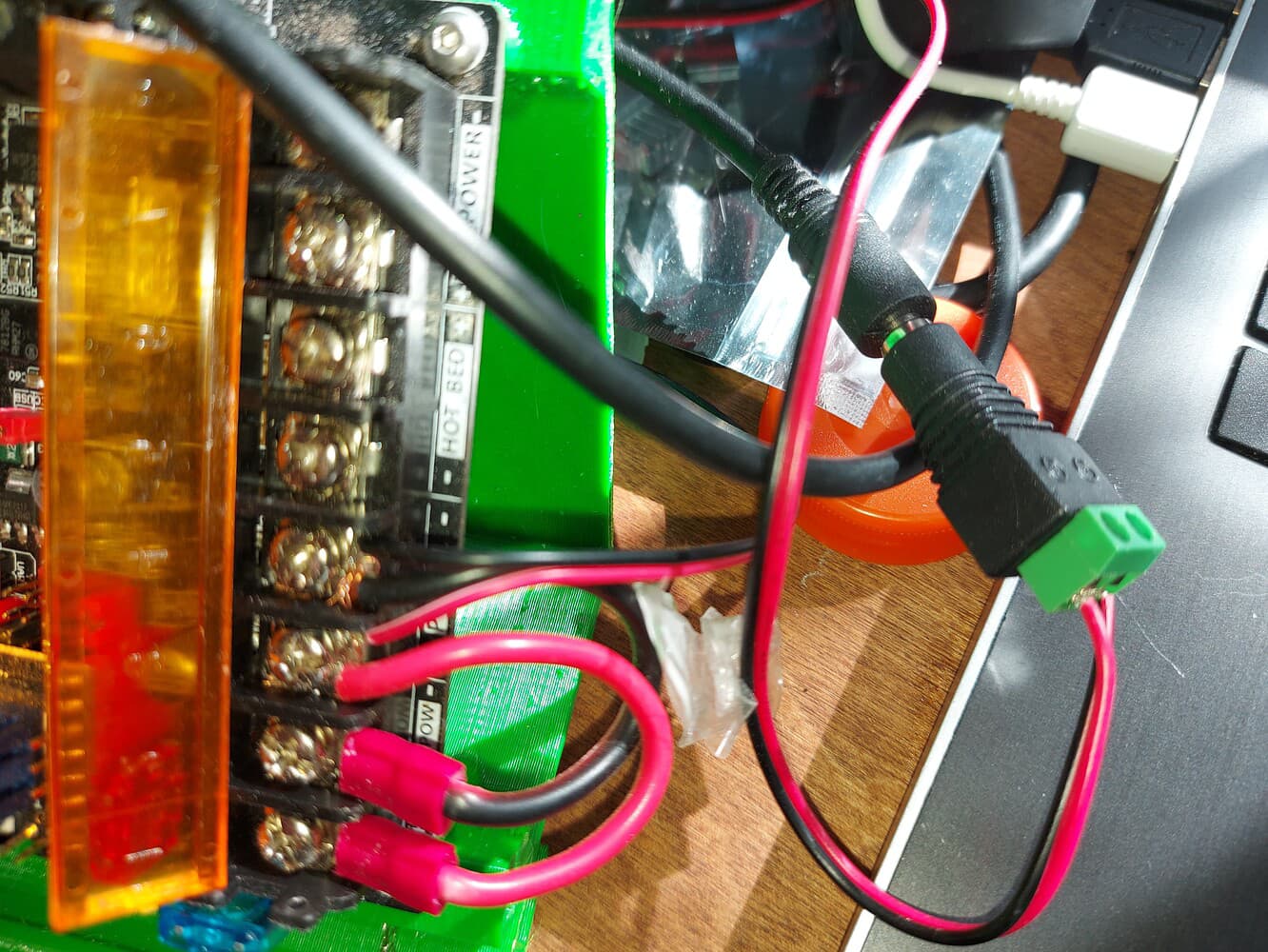
Hope that helps, cheers!

Yes, I think I understand it now. I got tripped up on the WAGU connectors. Two 3-conductor WAGU connectors were used, one for pos and one for neg. Then the spade connectors were spliced to the WAGU and run to the POWER and MOTOR screws. In the image above, it looks like it’s the jumper approach. I assume either would work, perhaps easier to use jumper method if you don’t have WAGU connectors.

Alos, your icon is the same as Aza’s Built to Code on YouTube. Are you the same?

EDIT: Forgot to ask - I’d like to use the barrel connector approach. Do you know what to search for when looking for that part?

3 Likes

Yep, either approach will work, lots of people do either approach.

Personally used WAGO because I had them, and prefer to use one wire per screw terminal when possible for more reliable connection.

Did your 24v power adaptor come with a barrel jack? My 12v power adaptor from V1E had one. If you need one, try searching “dc barrel jack connector 5.5”.

Yep am Aza, don’t forget to like, comment, subscribe and hit that notification bell :joy:. The montage is a bit manic, would slower content be more useful? Cheers!

1 Like

Already liked it, subscribed to your channel! I’ve been using your montage, frame by frame, to figure out what to do. It’s really fantastic and would be great as a resource link in the main build documents! I have hesitated to ask the forum for help because I’m so inexperienced. I’m coming at this project from a woodworker’s perspective and there’s been a learning curve for sure. I’ll post in the LR3 Builds page and hopefully what I’ve learned along the way will help others just like you do. Many thanks.

The 24v power adapter from V1E has a barrel jack but I’m not sure it would fit in any of the connectors I’ve found on Amazon. I’ve included a picture for reference. I’m sure I have another 24V power supply I can use that has a more common barrel jack.

1 Like

We have seen problems that came back to those barrel connectors. I just cut them off. I think Ryan intentionally removes them from the packaging now, because they were causing enough people problems.

Wagu is what I use. They are great.

Spade connectors… personally I prefer ferrules, I’m never too happy about the work hardening resistance of the metal in the spade connectors in any sort of vibration heavy scenario.

1 Like

I’ve wired up the SKR Pro 1.2 board to power using WAGU connectors. When I plug in the power adapter, the light on the power adapter turns off. I assume this means there’s a fault in the circuit. I’ve tried this with just the board, not screen attached and no steppers or end stops. I’m at a loss for how to proceed. Did I somehow fry the motherboard? This is a pre-flashed board from V1. Or am I missing something simple like a power on switch somewhere?

EDIT: I just checked the wires from the 24V DC adapter. Using a multimeter set to DCV, I read -24.8V when I have the black probe on the white wire and red probe on the red wire. Does this mean the polarity is reversed? That the red wire is actually the ground and the white wire is current?

Are yall talking about WAGO connectors (not WAGU)?

LOL, sorry, yes. Not the japanese beef.

I am not an electrician, but I do believe the negative voltage means that the wires are swapped. I connected my wires to where the positive is connected to the +voltage. It is working for me. I hope someone else comments if this is correct or not.

That did it! I swapped the pos and neg wires from the power supply (voltmeter reading positive value) and the board lit up!

I’m so glad the board has circuit protection. The electrical is the most challenging and there’s not much documentation. I’m taking pics as I go so hopefully someone else coming from a woodworker background has an easier time. Now to try and get these stepper motors turning!

2 Likes