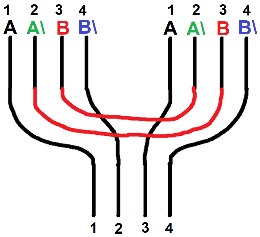
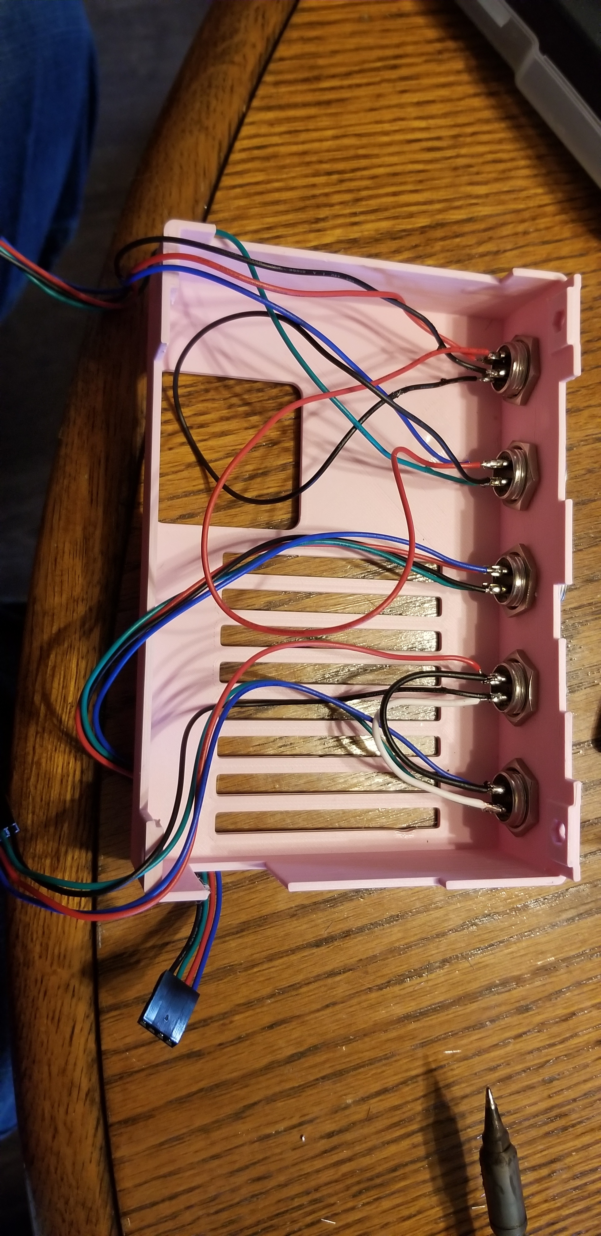
Hey, I am done building the MPCNC. Now, I need to wire it. since this is my LEAST confident subject, I want to make DOUBLE sure that I am doing it right. My Steppers colors are not normal (b and b\ are backwards). So, I am going by the stepper datasheet (card that came with it) to label the wires. also, I am using aviation connectors for the wires, so I will just wire those together. (series). Can some please confirm that this is correct? It is easier to ask now than have to un-solder and re-solder, or worse, burn up a board. Thanks for any help!
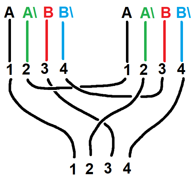
Closer but you still have one problem wrt Ryan’s diagram. From B\ on motor 1 you go to B\ on motor 2 and B on motor 2 goes to 4 on the connector. This wiring reverses the “polarity” on the B winding on motor 2. This results in motor 2 running backwards wrt motor 1. Given that the stepper motors are facing opposite directions, you need one of the motors running backwards with respect to the other to both drive the router in the same direction. Your wiring would probably work, but you would have to rotate one connector to get motor 2 to run in the correct direction.
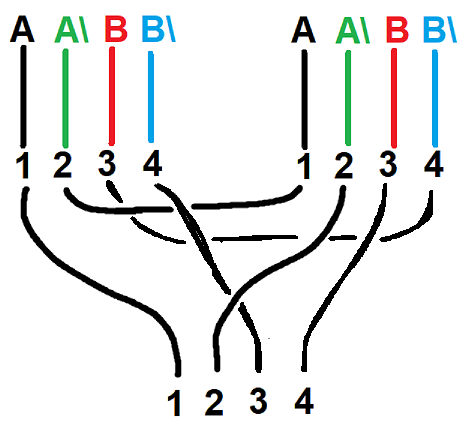
Nope, you only reverse the polarity on one motor. By reversing polarity on both B windings, you again have the steppers going in the same direction. So starting from your previous diagram looking at the B windings it goes:
3     ---> [1]B
[1]B\ ---> [2]B\
2[B]  ---> 4
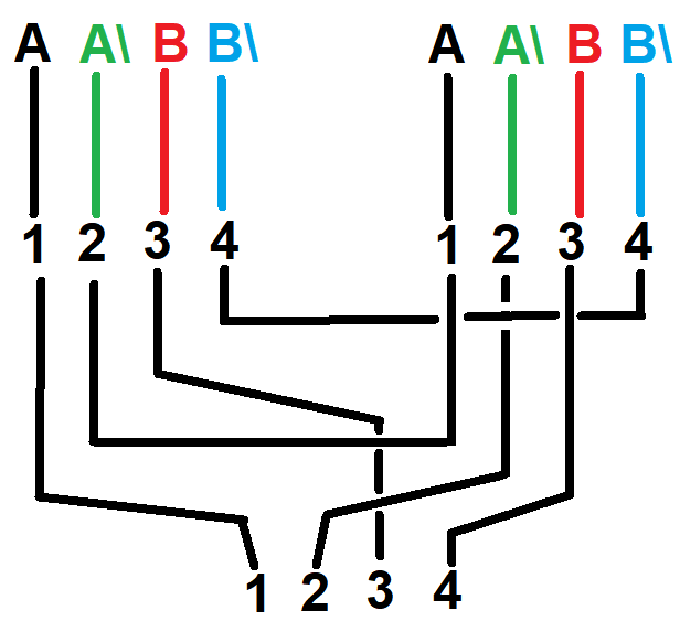
Again, either of your last two diagrams should work, but you will have to flip a connection. I’m just trying to get your diagram to match Ryan’s where if wired exactly as diagramed, the motors run in opposite directions.
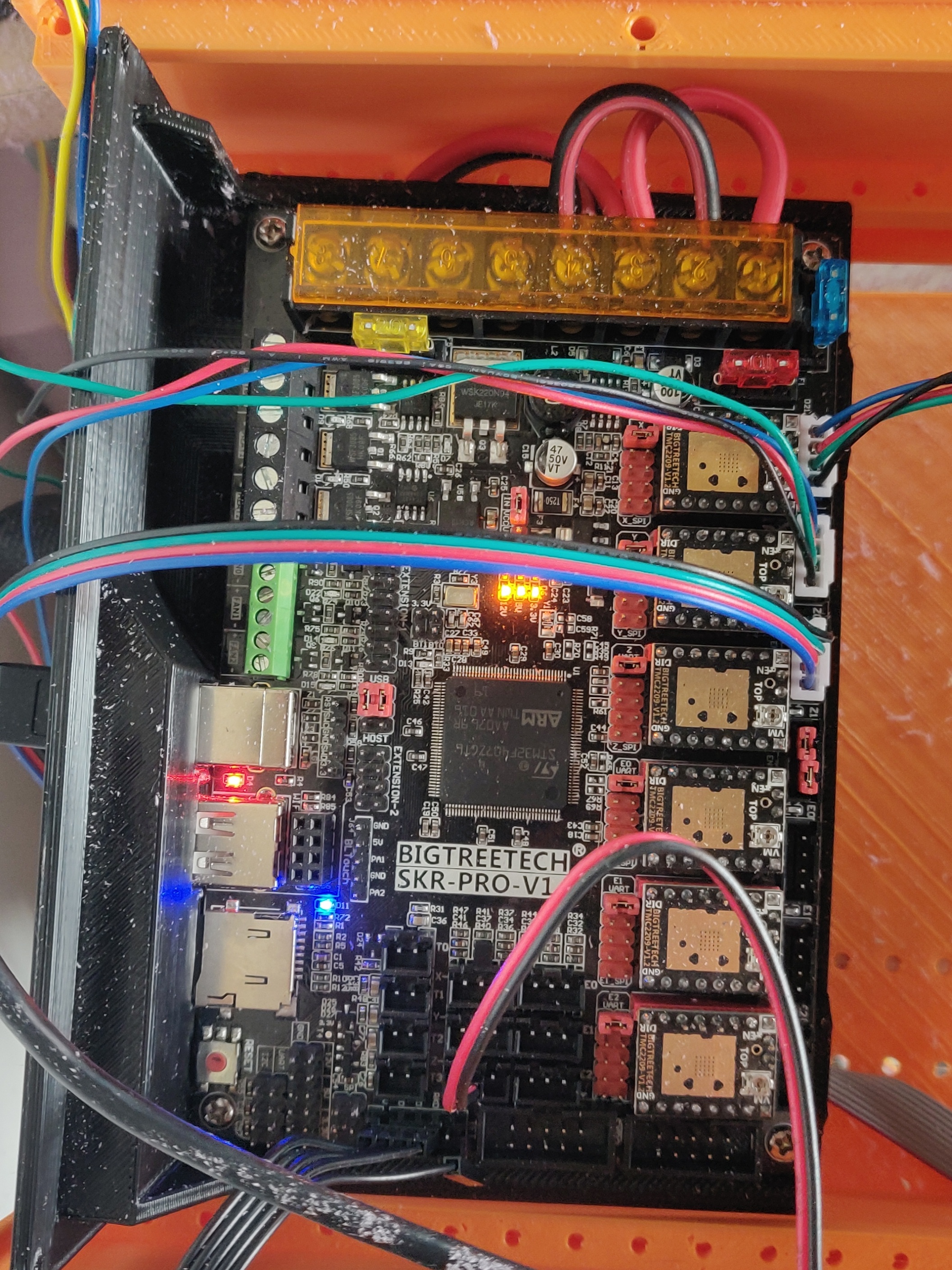
Ok, now I have a new problem. I bought the suggested Power Supply from the parts page (amazon) and it looks just like the one on the parts page. Problem is, there are two terminals on the end, and the wiring pictures show FOUR wires going to the board (SKR Pro 1.2). There are no images/ guides on how to get power to the machine. Do I just wire two cables to the one, or is there something I am missing that is implied?

