Another not-really-CNC project that would have been way easier with the MPCNC running but gives me a chance to have a play with 3D printed router templates.
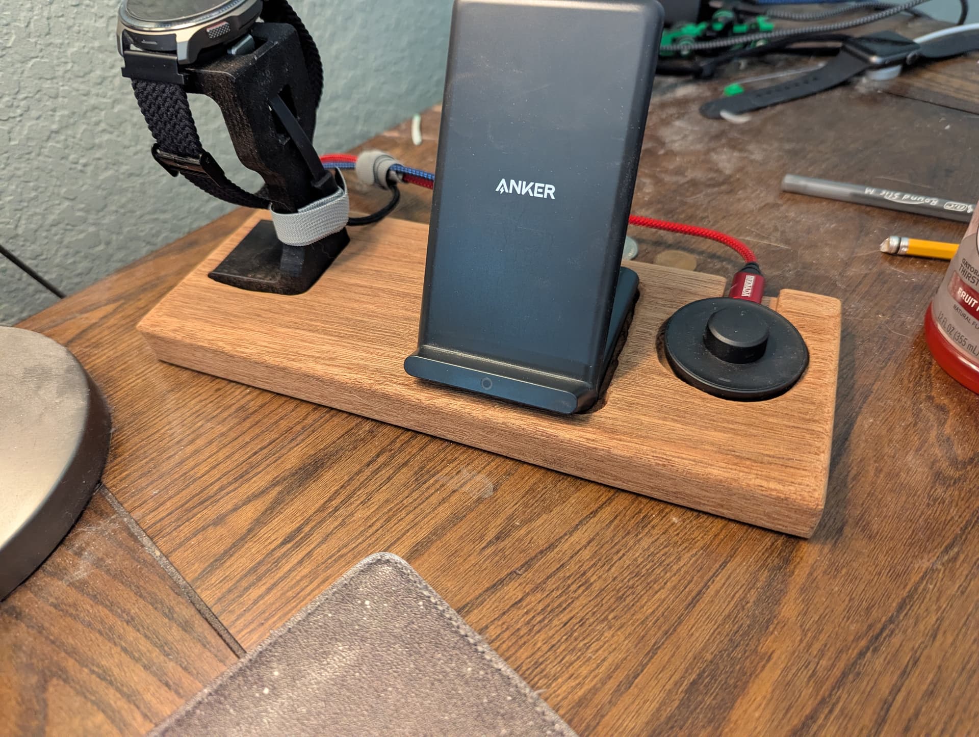
The goal is to make a new nicer casing for an off-the-shelf wireless phone charger. My previous ones were the same size/shape as the phone so they were easy to set down and have it charge. A lot of the newer cheaper options are just pucks that aren’t necessarily all that easy to align first try, so a new case that looks nice and is the shape of the phone would sort that.
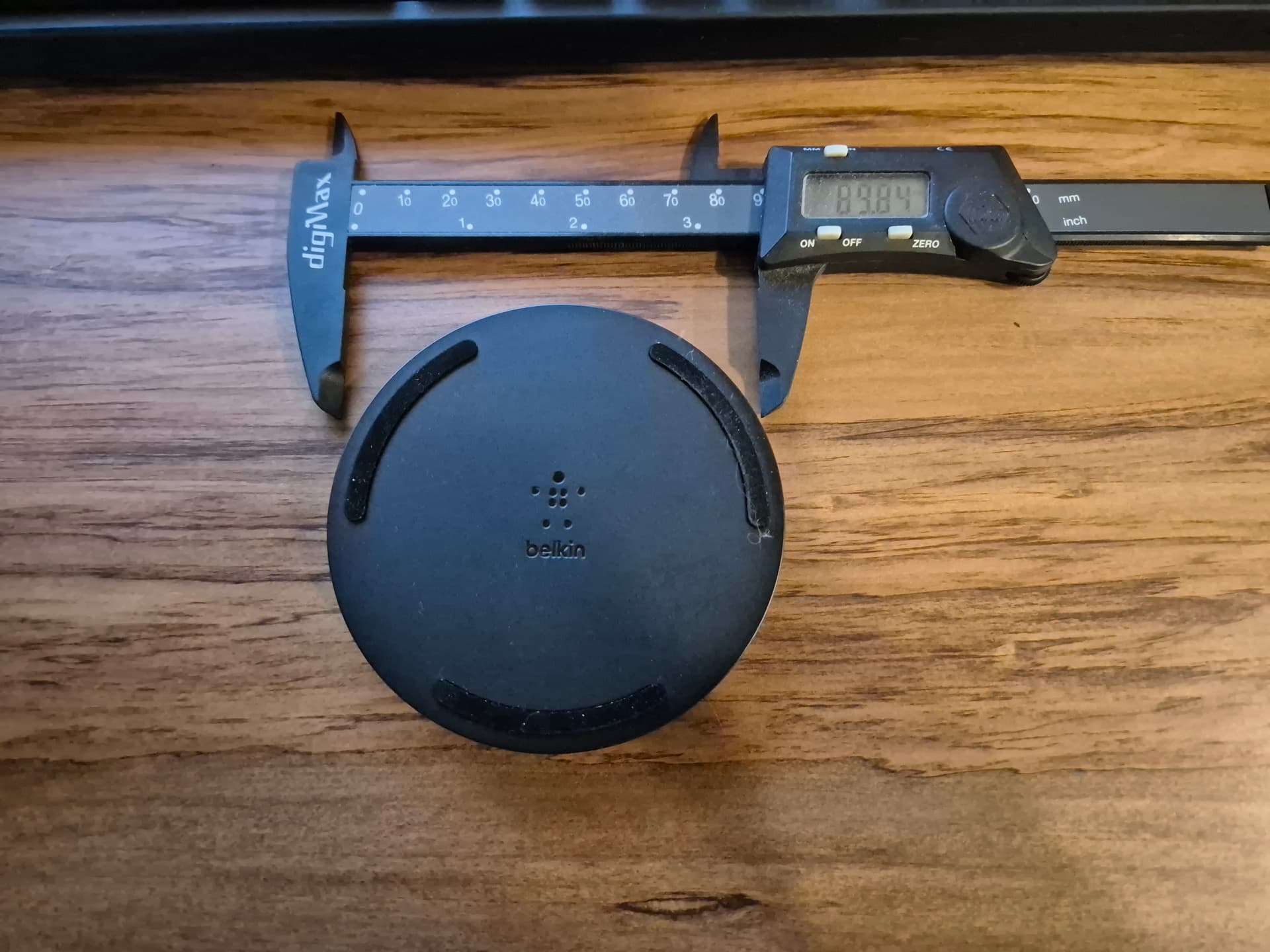
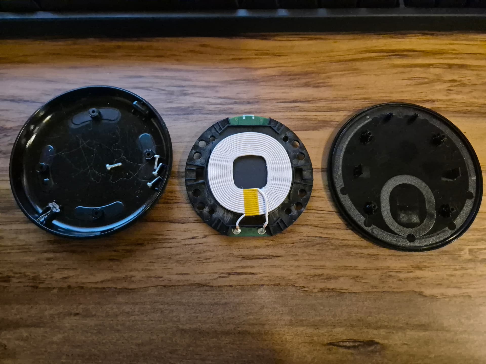
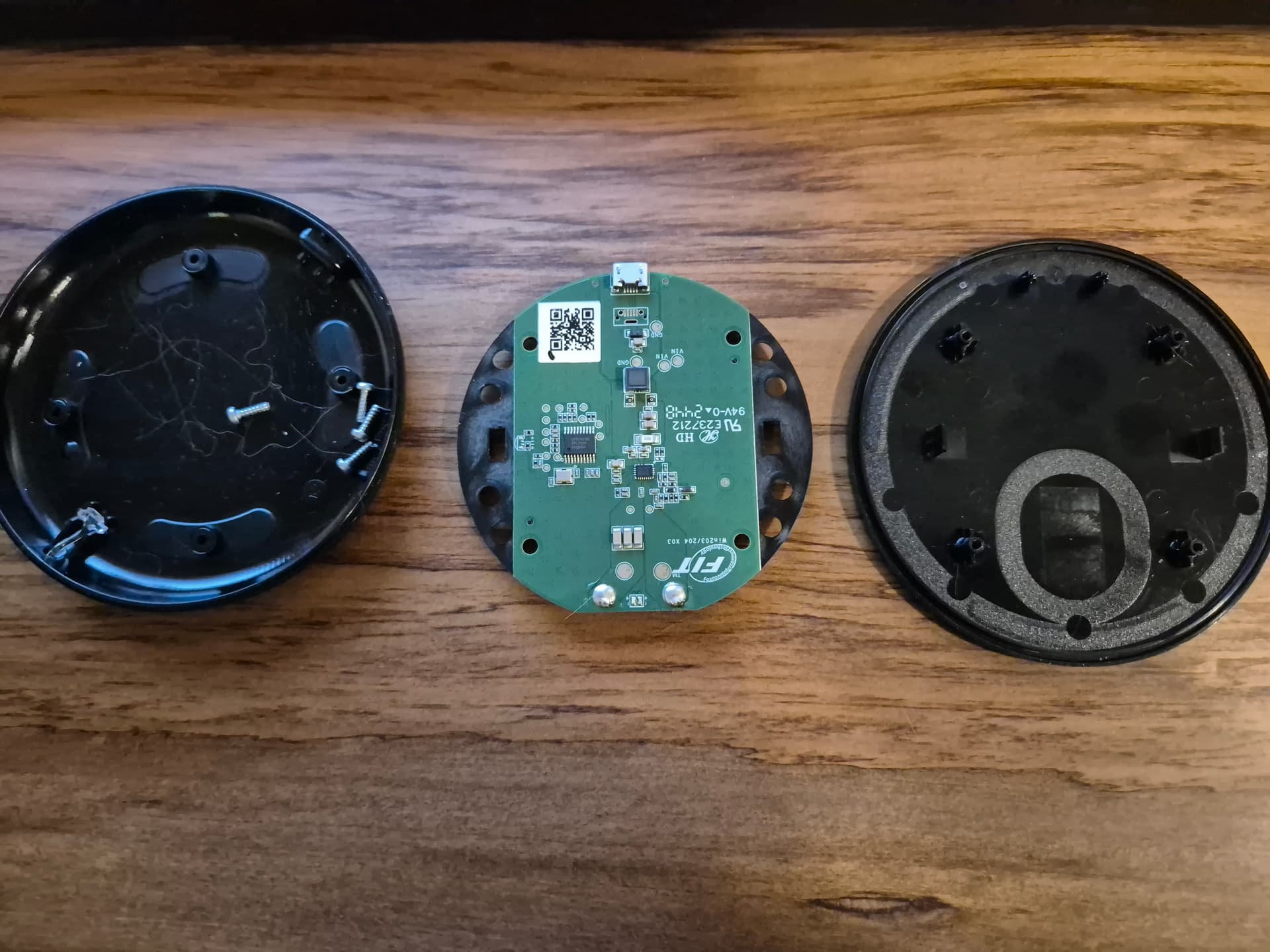
I chose a Belkin BoostCharge 10W puck style because I didn’t want anything too fast/complicated and hoped it’d be pretty simple internally. It was pretty easy to disassemble, just 4 screws under the stick-on feet. The internals are a circular coil and rectangular PCB all mounted on a plastic carrier. 74mm OD and around 5mm thick total. Measuring the case showed roughly 3mm from the surface where the phone sits to the top of the coil, which is plenty. Turning the phone over and placing the charging point on the back, I moved it up and down until I found the edges of where it would detect the phone and start charging, then used the halfway point between those positions to determine the best position for the charging coil, which was about 7mm offset from the middle of the phone towards the charging port of the phone.
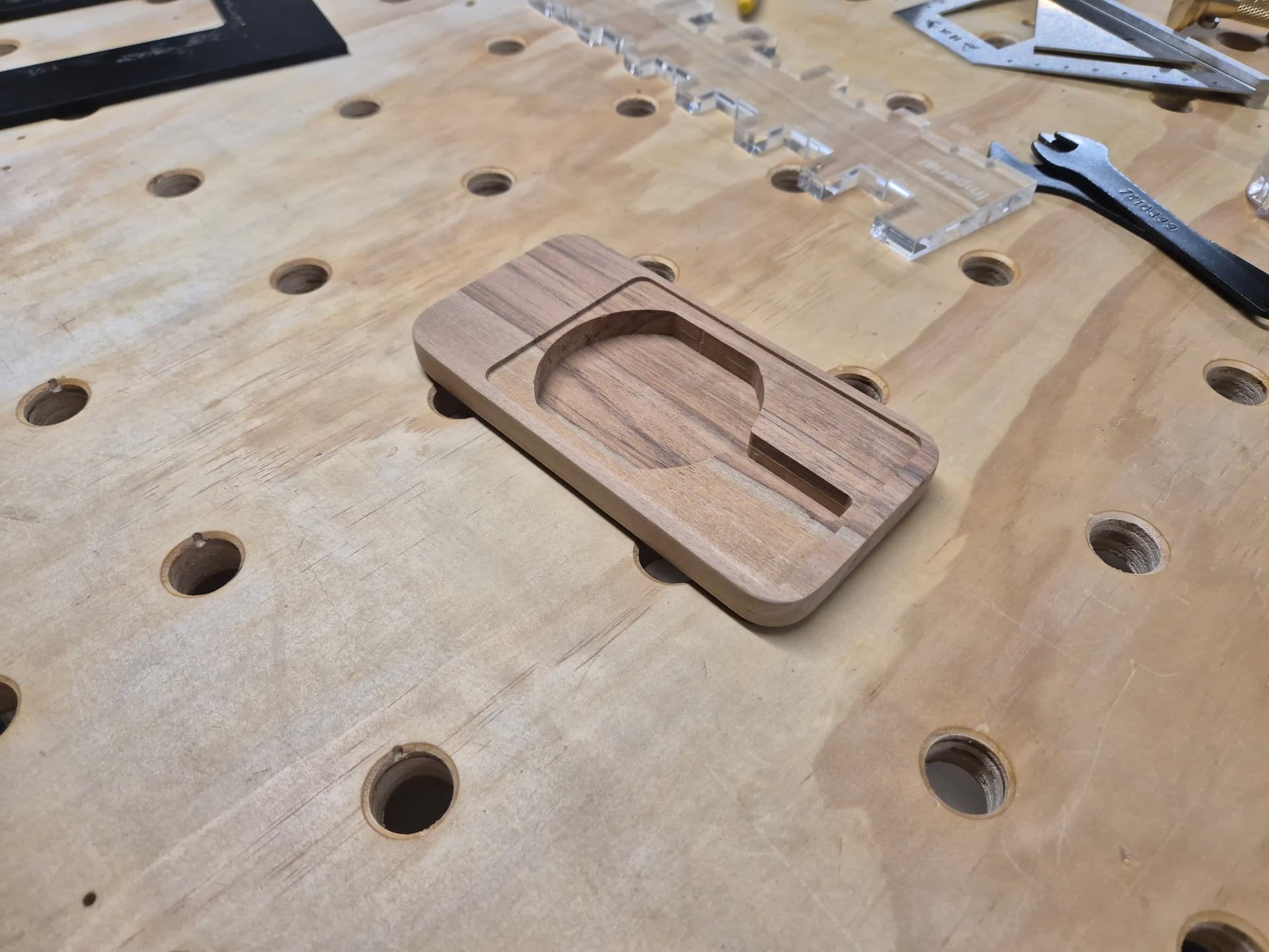
I modeled the shape of what I wanted it to end up like, which was pretty much just the shape of the phone then added a 75mm OD recess for the wireless charger as well as a 12mm wide slot for where the supplied USB cable and connector could go. The nice thing about modeling the shape was that I could check the section view to see how close the pocket got to the edges and I found that it was getting a bit thin if I used a roundover on the top. Two sides of the wireless charging module are just plastic so I trimmed those back by about 12mm with a pair of tin snips and squared off the sides of the circular pocket by about 10mm on each side.
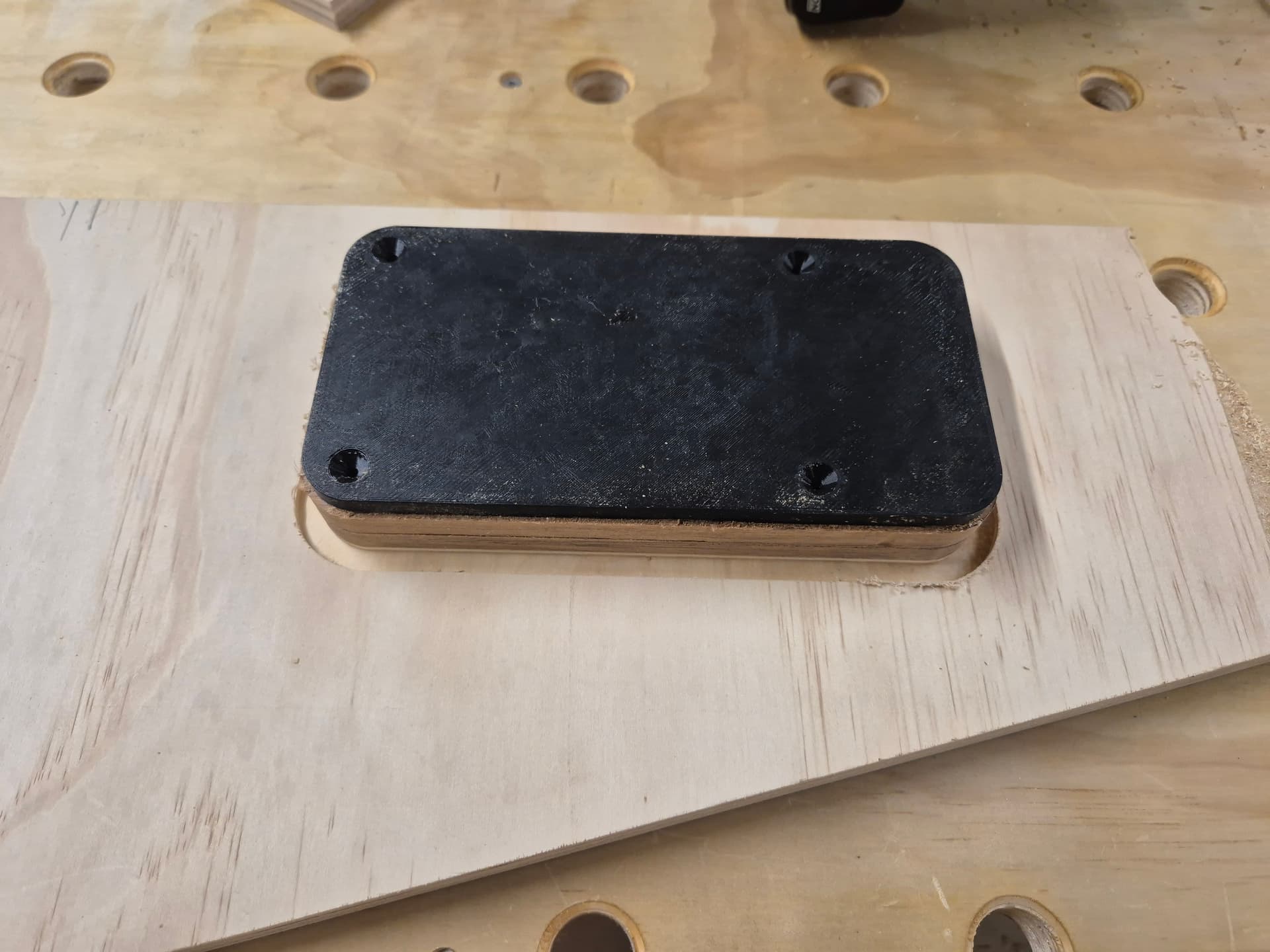
The original plan was to just hot-glue the wireless charging unit into the case and then put a cover over the cavity, but given that I was going to 3D print a cover for the cavity I thought that mounting the module to the cavity cover with some standoffs made the most sense. I designed a rectangular carrier plate that was large enough to cover the pocket for the wireless charger module and the wire channel. Some standoffs with locating studs gave a space for the unit to sit. I thought I would just hot glue the unit to the cover but with the heights being correct it all just sandwiches in place nicely, no glue needed.
The wood I used was an offcut from my desk build that was about 150mm x 100mm and 42mm thick. This was about perfect, apart from the thickness. I resawed it to 2x ~20mm thick pieces with a hand saw and then thicknessed the pieces down to 16mm to clean up the saw marks. Small pieces are mildly terrifying in a thicknesser so I’d usually mount them to a backer as a sled but this was a quick muck-around project so I just took light 0.25mm cuts and fed them in with a plywood offcut as a push stick. Still pretty hair raising, I wouldn’t recommend it.
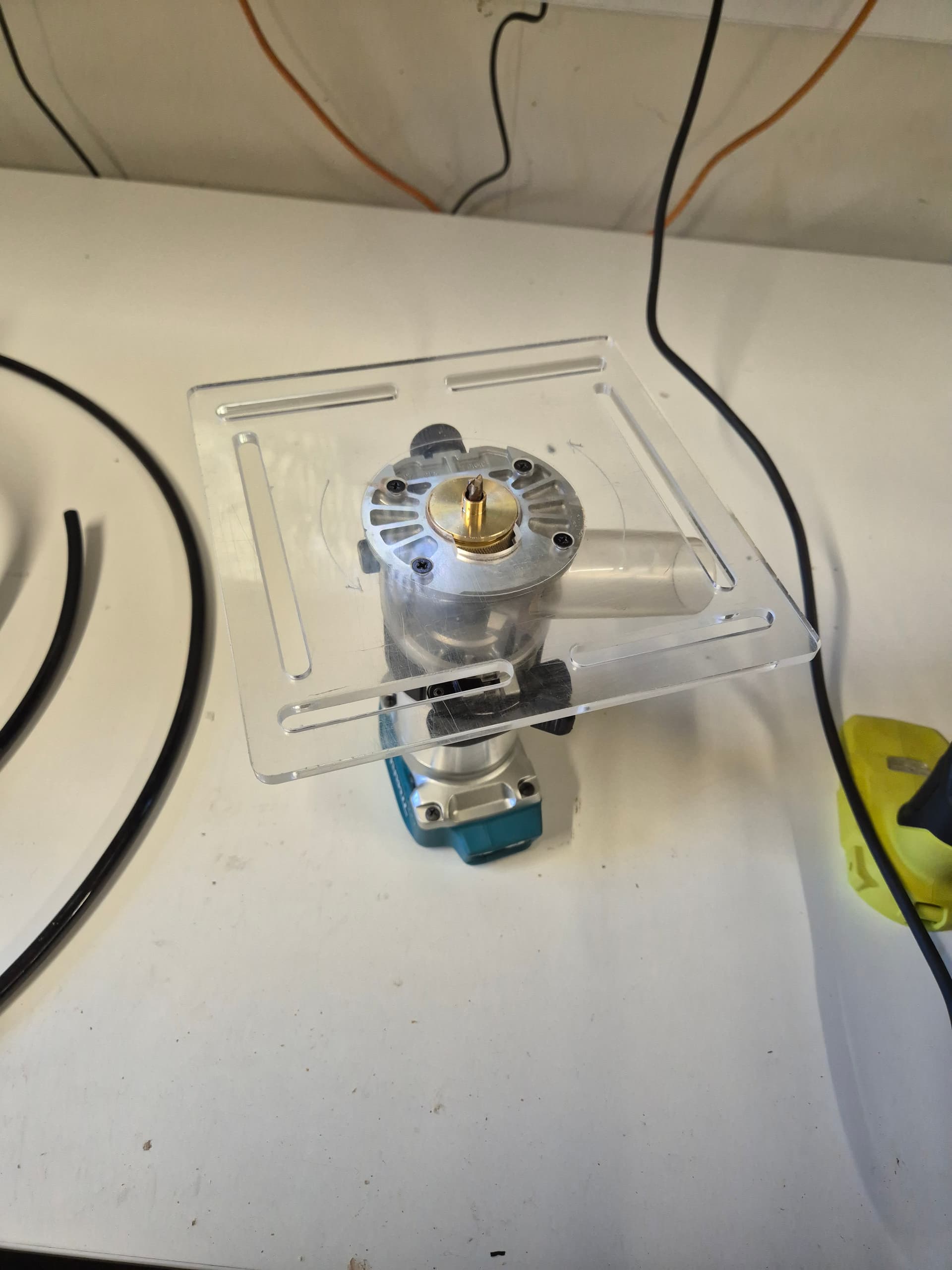
To make the piece I decided to do it with 3D printed templates for my battery palm router and a guide bushing. The guide bushing is 3/8" so ~9.5mm OD and I’d be using it with a 1/4" spiral carbide bit, so 6.35mm. The difference in radius between those is ~1.6mm so any template needs to be offset by 1.6mm away from the edge of the cut to account for that. The guide bushing also protrudes around 5.5mm so any template would need to be around 6mm thick. The bushing I’m using is a nice one from Taylor Toolworks and the large router base is one I made by laser cutting it out of 6mm acrylic.
I decided I needed 3 different templates. One for the deep pocket to house the electronics, one for the shallow pocket for the cover to recess into and then another for routing out the final shape. Thinking about the order of operations, I decided to do the shallow recess for the cover first because it was the largest internal shape. This would allow me to make the other templates such that they keyed into that recess. I 3D printed a 6mm thick template by making the exact shape I wanted using construction lines, then offsetting those outwards by 1.6mm to create the internal cutout shape. I bounded that with a rectangle with a decently wide border to give the router plate somewhere to ride on solidly.
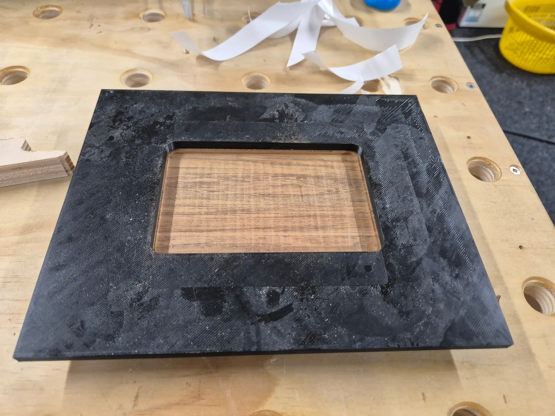
That’s after setting the router to a hair over 2mm and routing the entire pocket.
The next operation was cutting the deep pocket because I decided that would benefit from being supported by the larger workpiece before it was cut to size. Same as above, I designed the shape I wanted the cut to be using construction lines, offset those outwards by 1.6mm and then added a wide border and extruded it to 6mm thick. I added the shape of the cover recess from the previous operation and extruded that by 2mm to give it some way to locate with the previous cut.
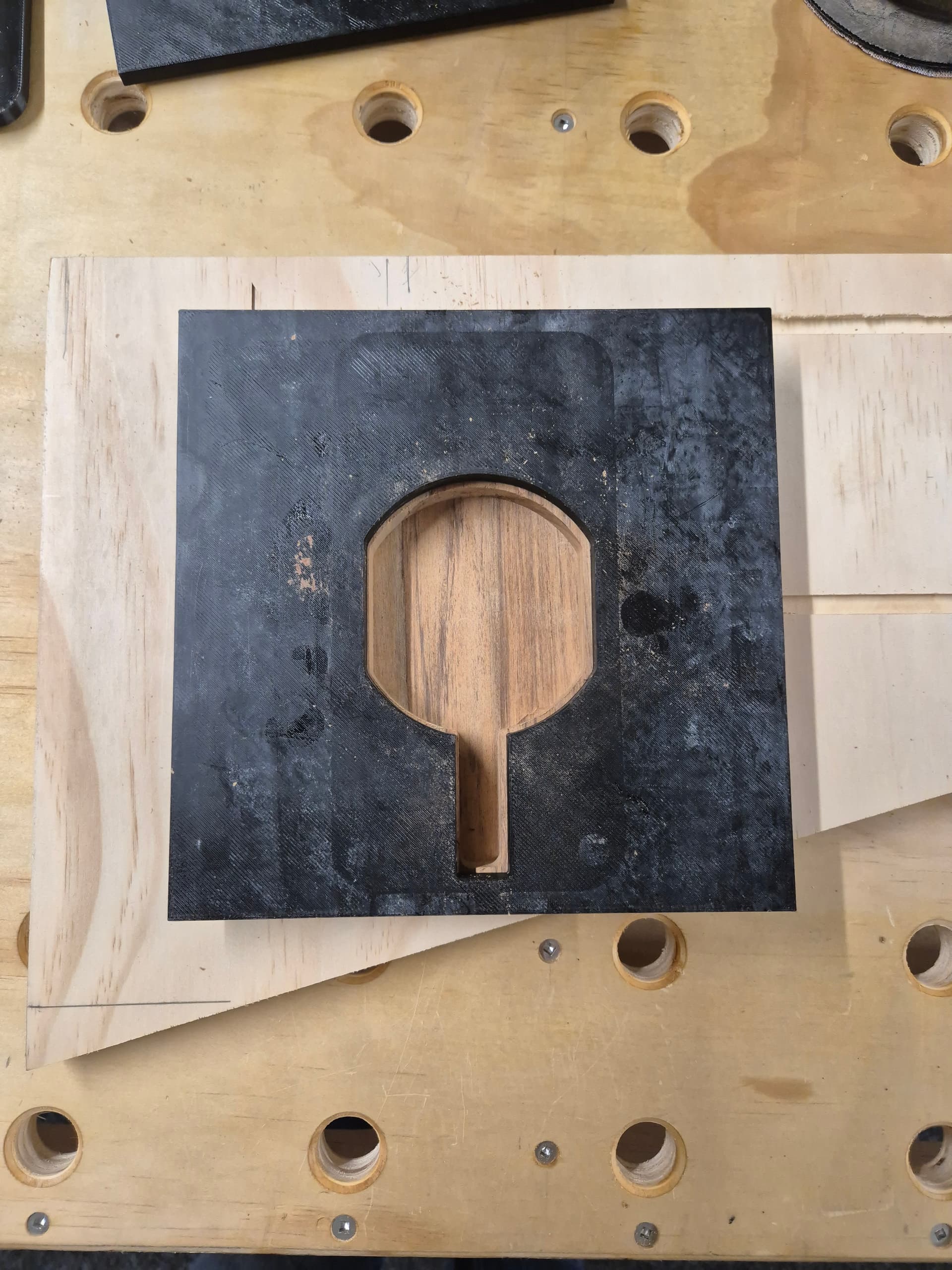
I did that cut in a few stages. It was ~13mm total to get to my desired 3mm final material thickness so I did it in 2 passes of around 6mm each and one final lighter finishing pass at 1mm deep.
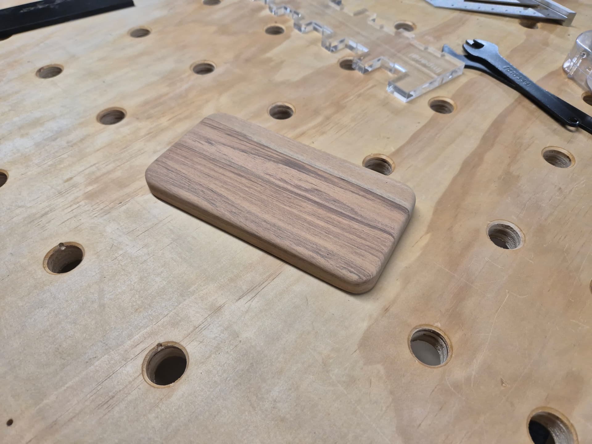
The last operation was routing out the shape. For that I designed a template much the same as above but with the shape offset inwards by 1.6mm. Same thickness, same raised area to key into the recess from earlier.
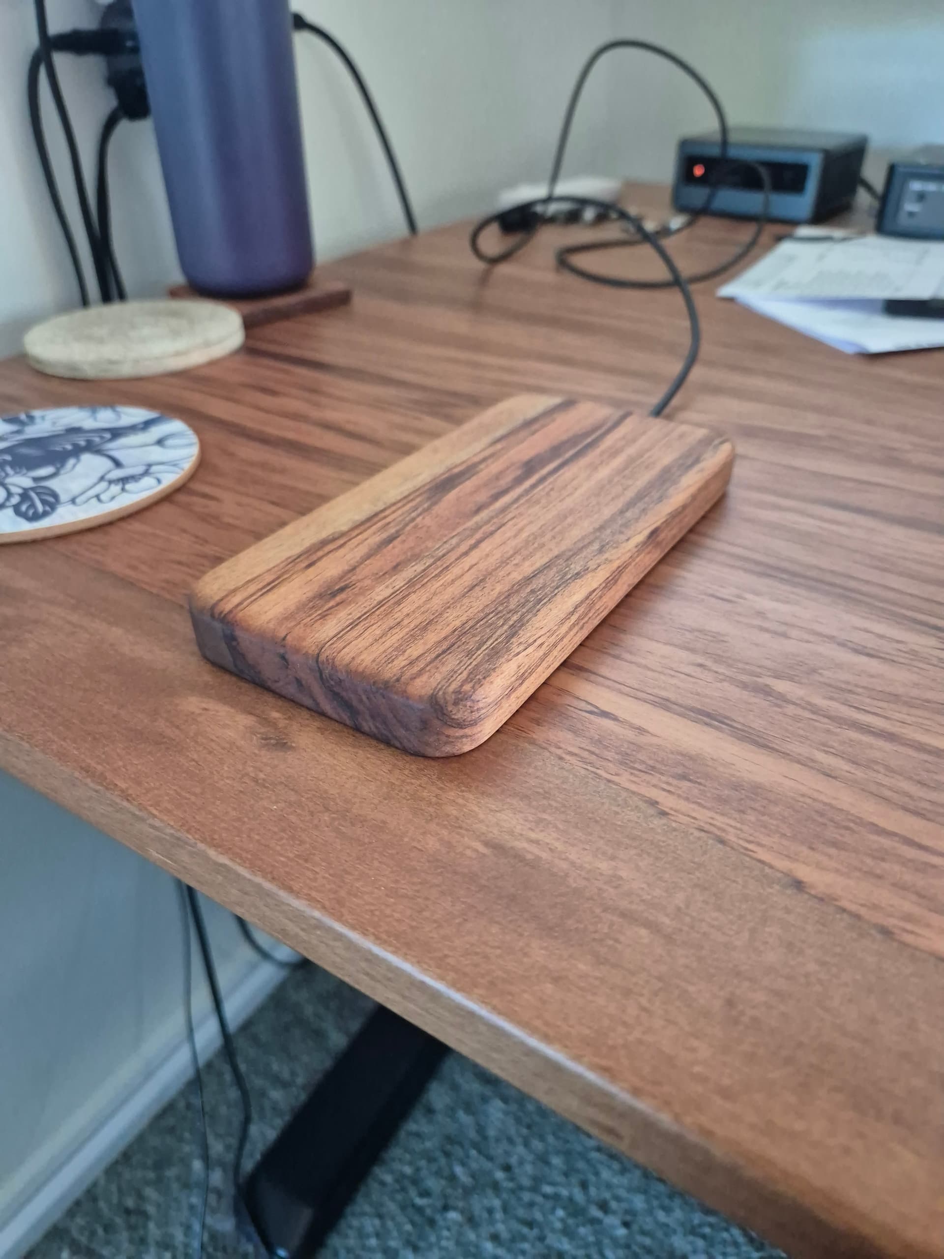
For that I stuck the piece down to a plywood offcut as well so that I could cut completely through and did the cut in 2 passes. After that I sanded the outside to remove the seam from the 2 passes and to clean up all the curves then ran a 5mm roundover bit over the top edge. I also broke the sharp edges on the bottom and in the pockets with some sandpaper. I also hand-filed a recess for the USB cable to go through with a needle file. I went just deep enough that the cover would slightly pinch the cable, creating a little bit of a clamp on the cable.
I gave the outer surfaces a good sand with a an orbital sander at 120g and 180g before hand sanding at 240g, water popping the surface and then re-sanding at 240g. Final step was a good soaking in Rubio monocoat. I probably didn’t need to finish the inside but it’s not a bad habit to get into to avoid warping over time and I did hollow the block out a fair amount.
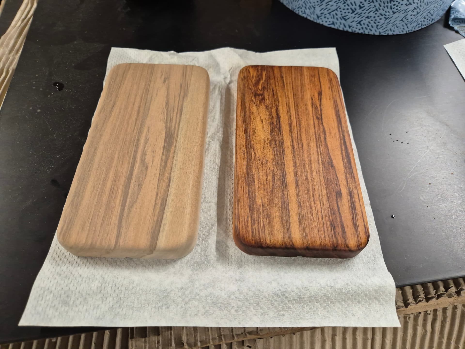
I had 2 pieces due to sawing the offcut in half so I made a ‘matching’ pair. I’ll grab another charger later today and assemble another one for my fiance.

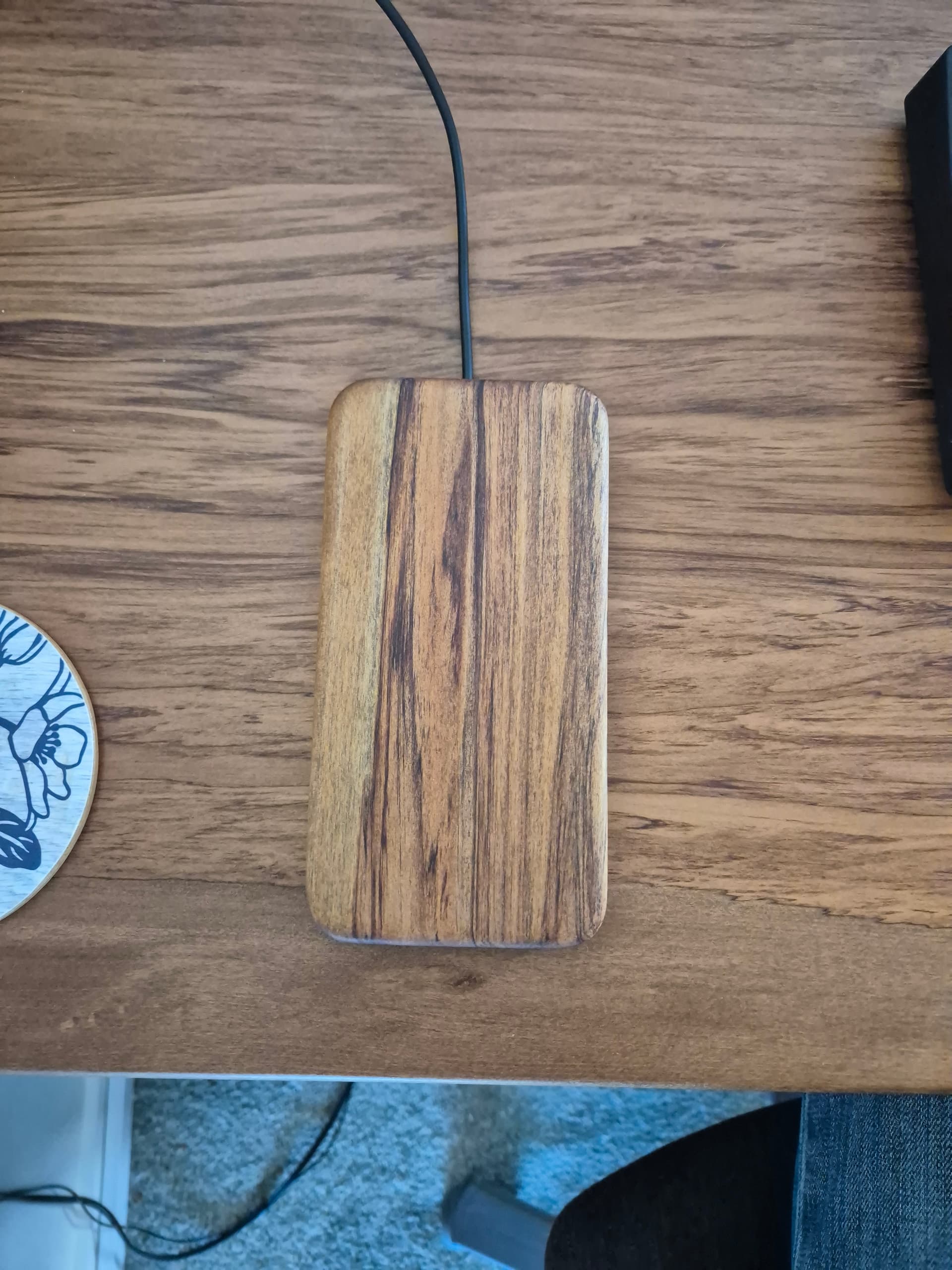
Final assembly was to set it all in place, pilot drill the holes and then mount the cover in place with some 8g x 10mm stainless wood screws. A bit ridiculous but they’re what I had on hand. Once the Rubio has hardened up in a few days I’ll add some stick-on rubber feet on the bottom.
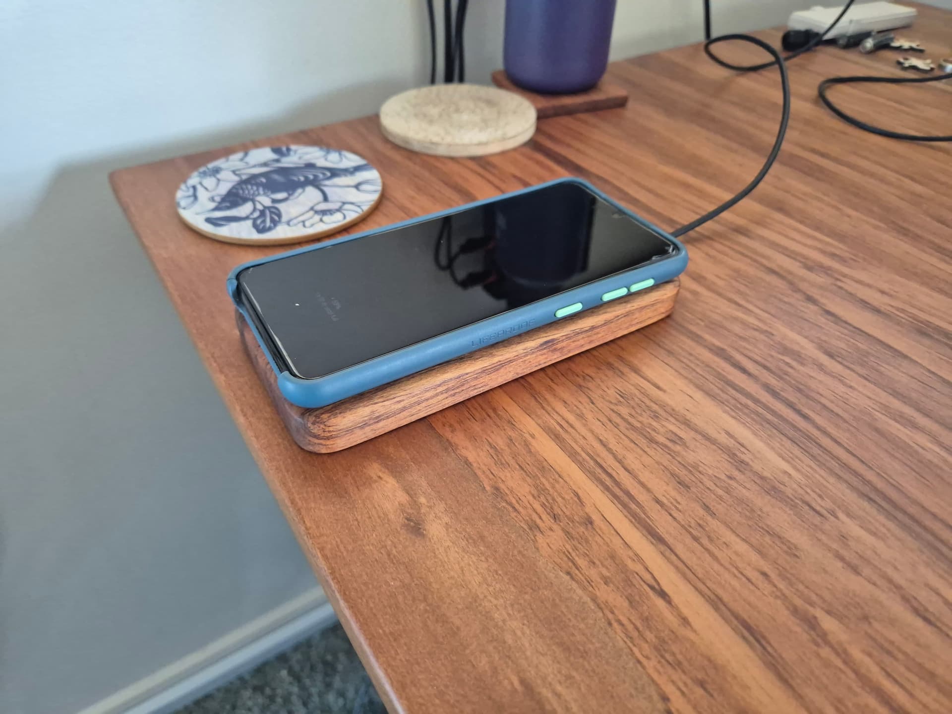
And the final item. The bumper case on my fiance’s phone makes it overhang slightly but she says she’s fine with it. Worst case I’ll remake one with a larger overall size to match hers a bit more closely.
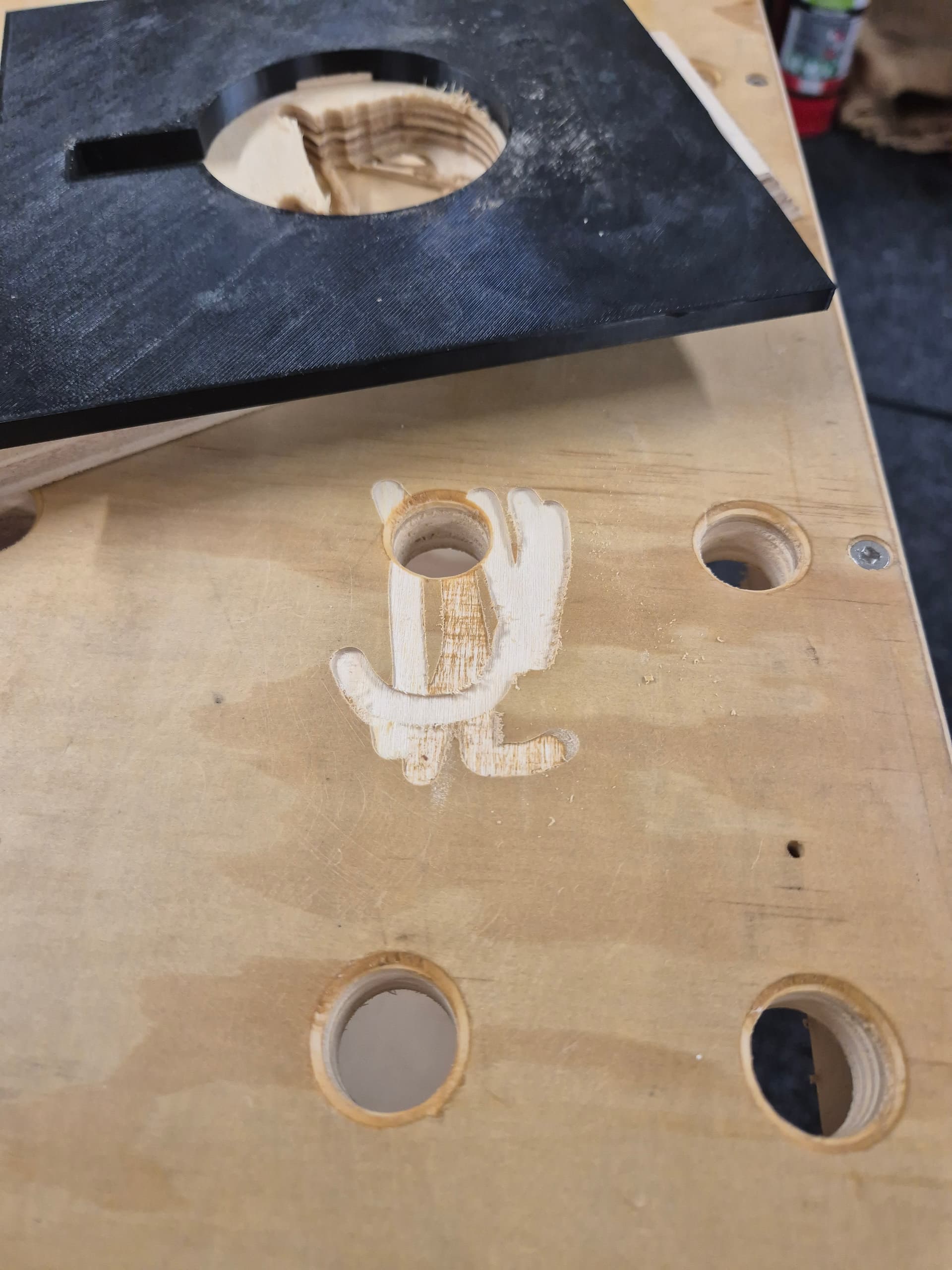
I tested the whole process out on a spare piece of 18mm plywood first. This was a good thing because while routing the deep pocket the bit slipped and pulled out of the collet, resulting in my routing a 5mm a remarkably ugly deep slot in my workbench. Damnit. Amusingly, I also managed to cut into the edge of the table slightly while resawing the piece, so that’s all going well! It adds to the 2 tracksaw cuts, a couple of extra drilled holes and a big dent, so not exactly like it was all pristine, anyway.
Anyway, that’s another not-a-CNC project that would have been remarkably easier if I’d just set up the MPCNC, but it’s also fun to play with things like using hand made, laser cut or 3D printed templates sometimes.
All up I think I spent maybe an hour on the CAD and maybe 3 hours on actually making the parts over the course of one Sunday afternoon/early evening. Most of the stock prep was done while while waiting for the next parts to print and then each time a template finished I’d go use it while waiting for the next one.
If I were using the MPCNC then obviously all of those operations, including the thicknessing, could have been one job with no toolchanges and would have likely taken about 20 minutes of actual cutting time.
Some final thoughts:
For the templates themselves, I printed them in PETG because that’s what was loaded but damn near anything would work. I printed them fast with default settings and 10% infill because they don’t need to be all that strong. Each one took around an hour to print and took 60-70g of material. All up, including 2 re-prints as I changed things I think it was maybe 1/3 of a roll, so ~US$5 of filament and 5-6 hours printing. It’s a good idea to file out any bumps/seams before using the templates because that will transfer to the cut. Not usually an issue to sand afterwards, but filing the template is quicker and easier.
Double sided tape in a dispenser makes this whole process a lot easier, both for the templates to the work and the work to a spoilboard or to the bench.
Tighten your collet nut well, especially when using carbide tooling. Damnit.
The whole thing is also quite a lot lighter than my phone so if I do another one I’ll probably try to add some weight, either in the form of making the cover out of steel or drilling some holes to press some weights into. I have a large quantity of leftover hand-cast .45ACP projectiles that work well for that kinda thing but steel nuts/bolts/screws can work well too.
The nice thing about using a palm router is that it’s lightweight and easy to keep upright when using a guide bushing like that. The downside is that there’s no good way to center the guide bushing so the offset between bushing and cutter is often inconsistent. I got around that by just keeping the router oriented the same during every cut. That makes the pocket correctly sized but maybe 0.5mm offset from the template. You can also deliberately orient the router to follow the cut to keep the pocket aligned but potentially over/undersized. You can also use that technique to do an easy finishing pass by using the ‘wider’ offset for the first passes and then finishing by rotating the router 180 degrees and using the ‘narrower’ offset for the final pass. That’s a pain in the ass with a dust hose, though.
Guide bushings are awesome, especially when using a larger plate. I like using them a whole lot more than a pattern bit. The only downside is you need to account for the offset between cutter and bushing. The upside is that you can easily do very shallow pockets or deep cuts in fewer passes without worry. Also no bearing marks on the work etc.