Opinion needed here. I have a NEJE E40 laser module wired up with about 8-10ft of 20ga wire. The module says it should need atleast 3 amps to run at full strength. Can my current wire handle that or should I upgrade to a thicker gauge?
I am thinking I need to upgrade to a thicker gauge but don’t want to tear out the cable chains unless I absolutely have to…
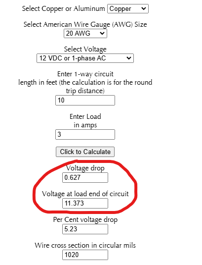
Should I be concerned about the voltage drop? The calculator below shows my voltage at the end of the wire is 11.373. Is that enough of a drop to have notable impact on the strength of the laser?
That’s one of the downsides to cheap electronics, they’re poorly specified so it’s tough to tell. Given that it will be a switching controller inside, I wouldn’t expect it to make a difference to the output power, but the input current will rise as the input voltage drops.
The page for that laser says that it recommends a >3A power supply, not that it draws 3A. The Input section of the specification says 12V 4A.
If you’re worried, you can always run 2x 12V and 2x GND wires of the same size to it, which will effectively halve your voltage drop.
Edit: From looking at the Wiki, it notes that the input power for the A40640 is around 40W and that they supply a 12V 4A or 12V 5A power supply for that, so they’re building in some overhead already. They also note that some cheaper supplies will drop to 9-10V when trying to deliver 40W which means there isn’t enough voltage for the laser to operate at full power.
I think I’d probably either double up the 0.5mm²/20AWG or run 1mm²/17AWG instead, just whatever is most convenient.
Also bear in mind that a lot of power supplies only specify the output voltage to +/- 10% or even worse in terms of accuracy/line/load, so a 12V supply can easily be 10.8V under load, even for a relatively decent one. Add 700mV of voltage drop to that and you’re starting to get into questionable territory for a lot of stuff.
So regardless of voltage drop etc. it’s worth checking the actual operating voltage at the terminals when the device is in use.
For things where it’s critical, that’s why I like using DIN rail mount supplies where it’s more common to have some level of trim/adjustment. Often electronics don’t mind a 12V supply rising up to 13V unloaded but are much more likely to have an issue if it drops to 10V loaded.
I tend to over engineer things like this, but I’d go with 18AWG or 16AWG to reduce the voltage drop. Due to some electrical issues, I reran the wires for my A40640, and I used 18AWG over a smaller run to deliver power to the laser.
You don’t specify how you are wiring your laser. If the control board is not on the laser mount, the temperture line and the signal (PWM) line can be much smaller.