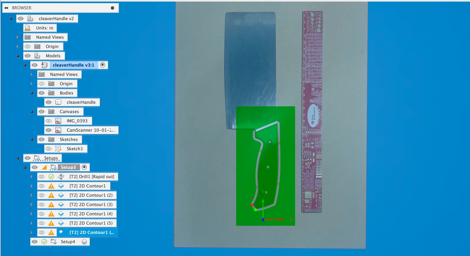
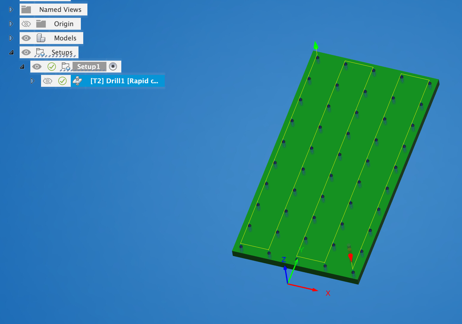
Finishing up the gCode parsing right now. Still need to make a little workflow for the holes, but I don’t think that’ll be too hard. I have something fun in mind
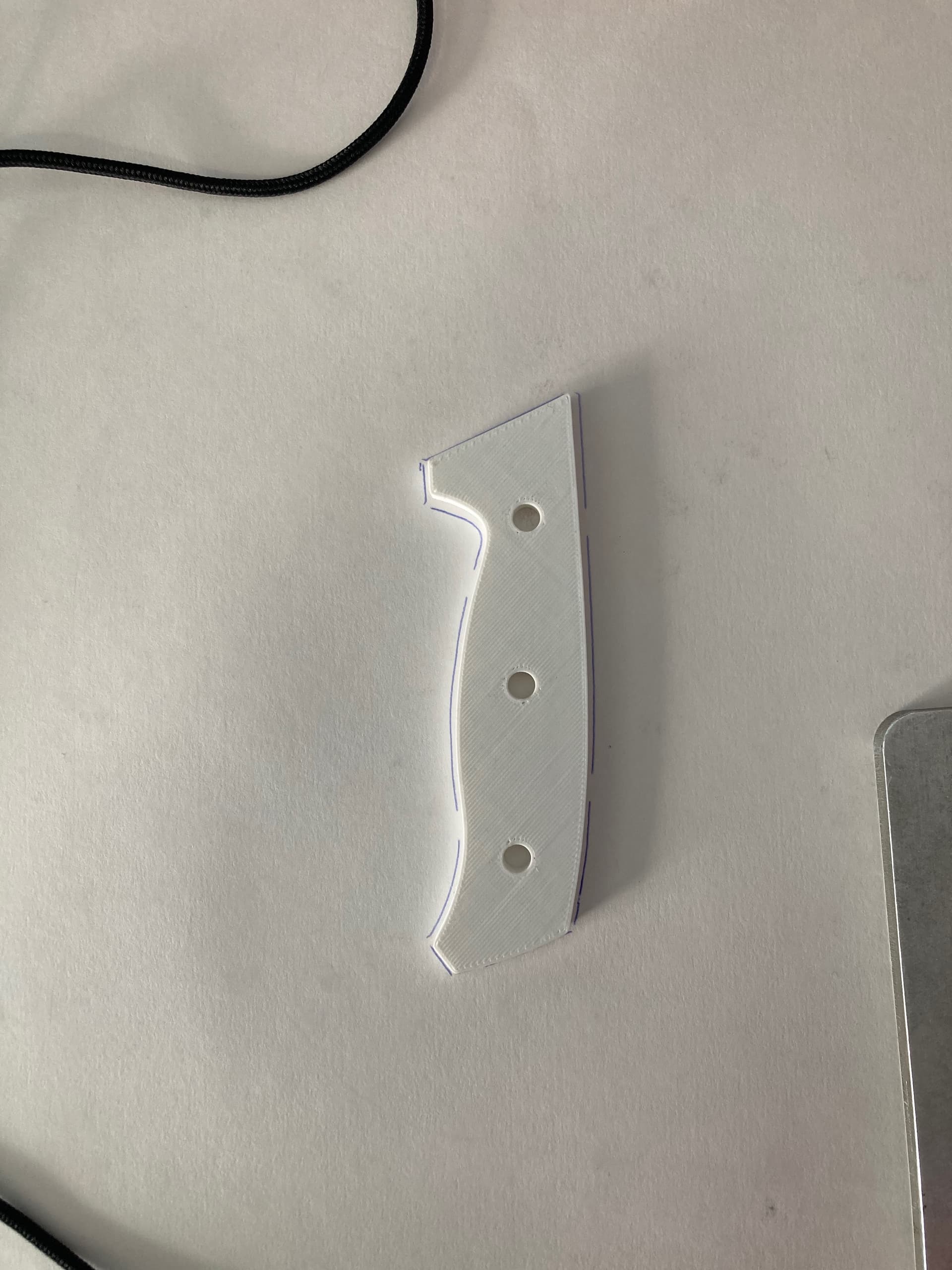
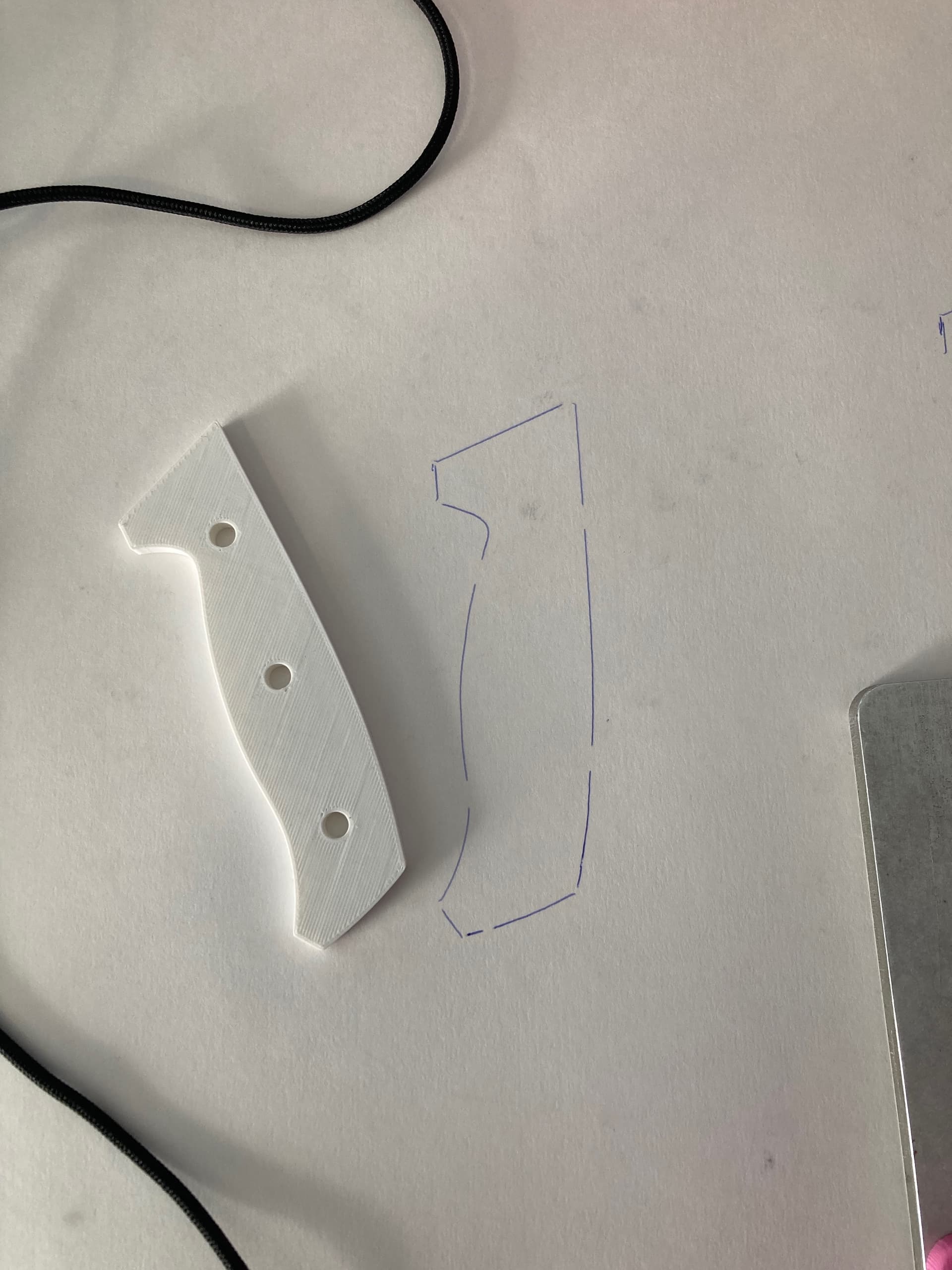
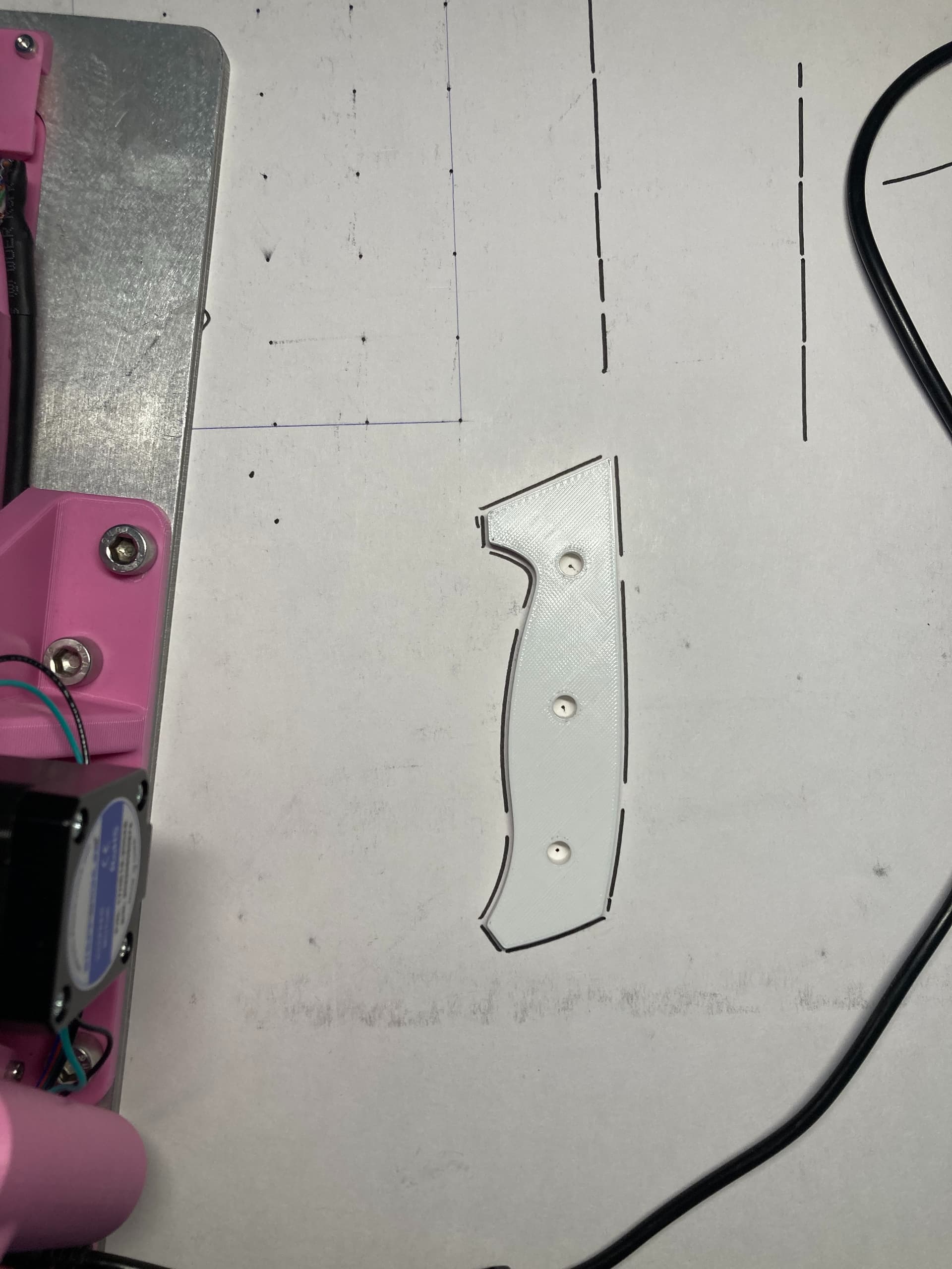
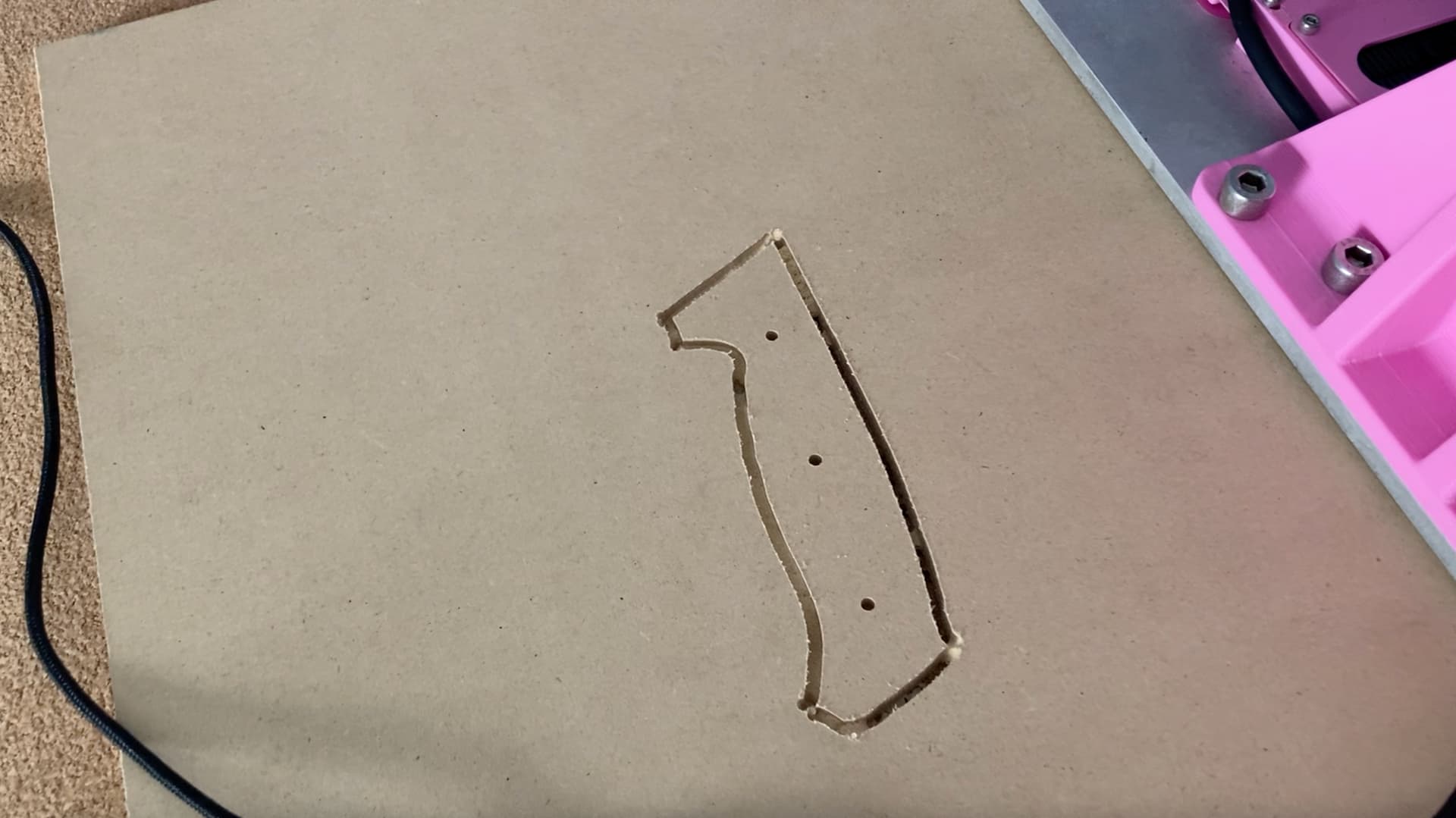
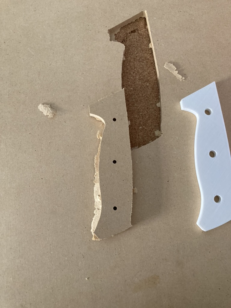
Did a couple tests on MDF but for some reason the firmware is bugging out going from the drill operation to the contour operations. I’m sure it’s a silly line of code I’m overlooking. The holes look decent, but not amazing. As you can see in the picture, the drilled holes are little squished compared to the 3D printed mockup. The camera perspective makes it seem a little worse, but there is definitely something there.
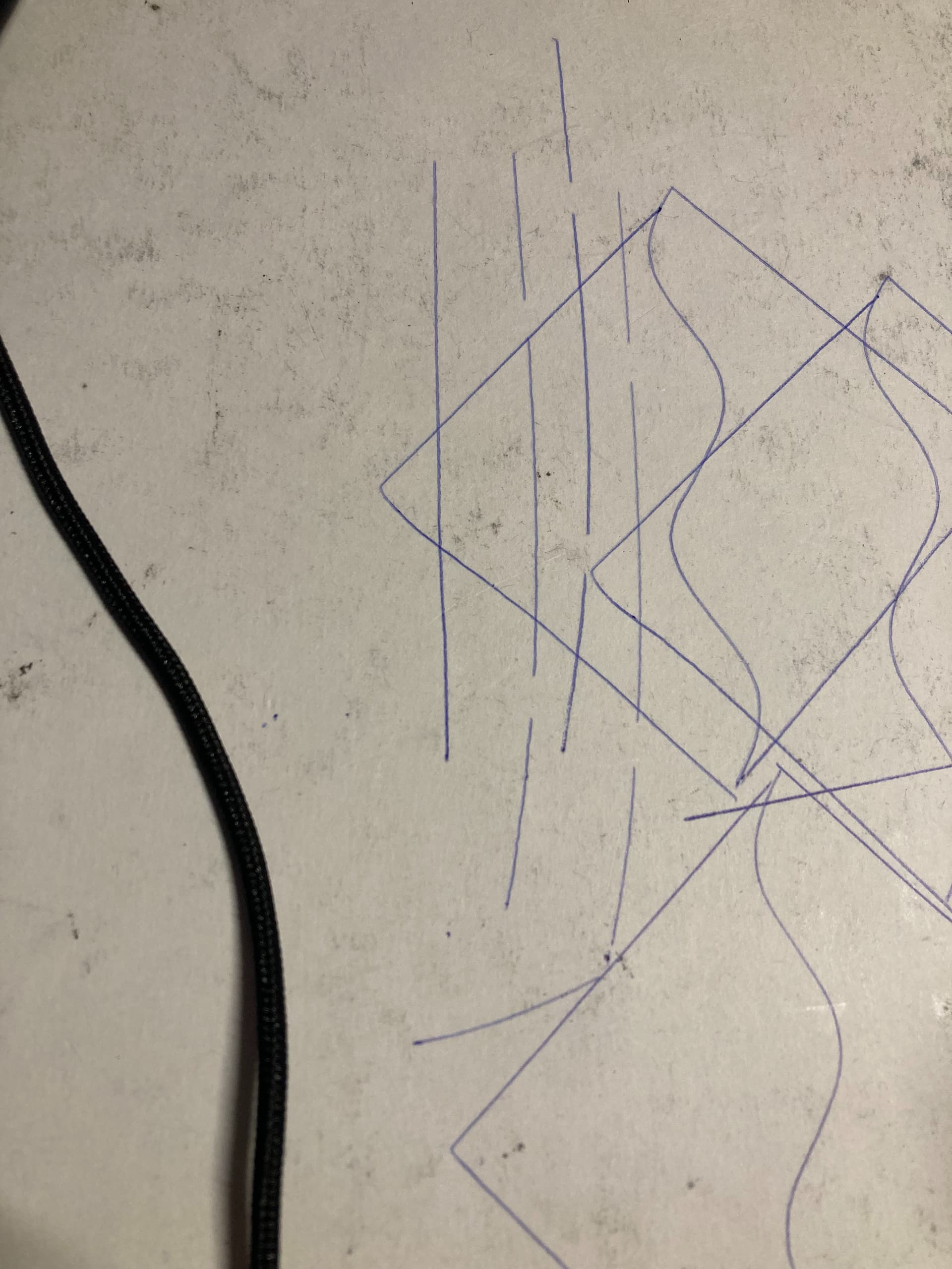
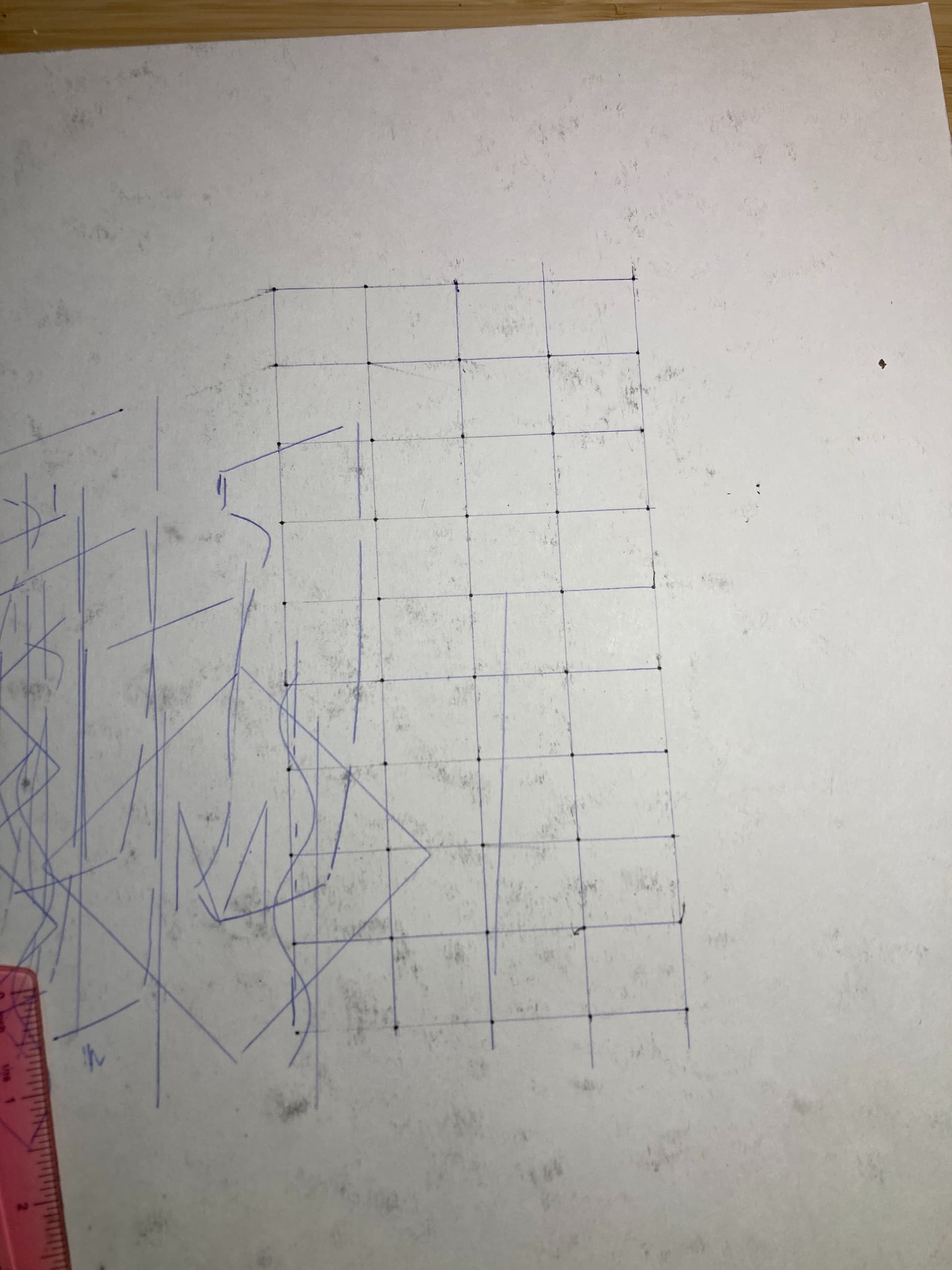
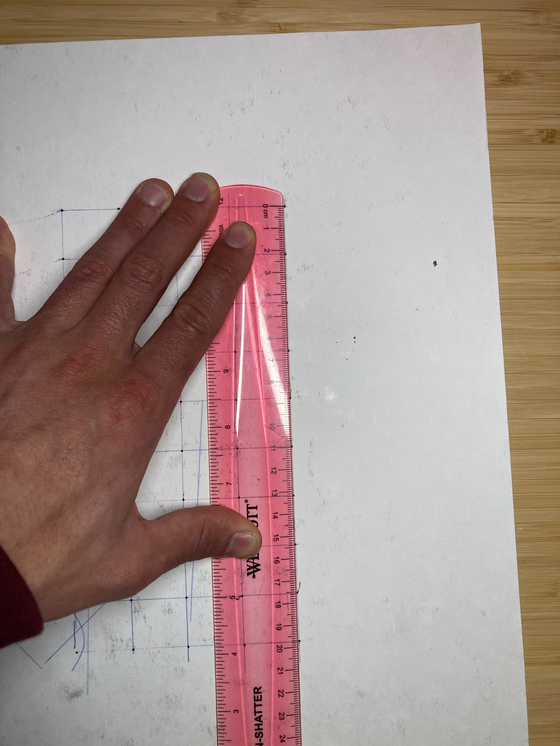
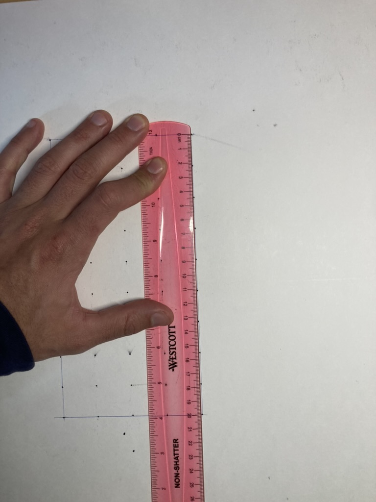
They all seem to be square and consistently in line, not drifting noticeably through the operation. After measuring the distance, though, it does seem that the vertical pattern is a little “squished” (188mm extent instead of 200mm, so about a 1% skew).
This seems to be consistent through all 5 vertical lines, though, so it makes me think that it’s just a calibration issue. I’ll try recalibrating it in the morning and see if that fixes it. Speaking of calibration, this whole grid plotting exercise is giving me ideas for an improved calibration process. More on that in the future, though…
Not that I’ve found yet. The most important thing is for there to be enough features on the surface. I could see a potential issue with reflective, shiny, or clear surfaces, but I haven’t tested on anything like that yet. For a really tricky material like clear acrylic, you could always just get around the problem by covering the surface with something opaque - either taping a piece of paper on it for the cut, or just leaving on the film that normally comes with it.
Recalibrated and we’re looking good now. That seemed to solve it. They must’ve gotten rustled up a bit in my luggage while coming back from the holidays.