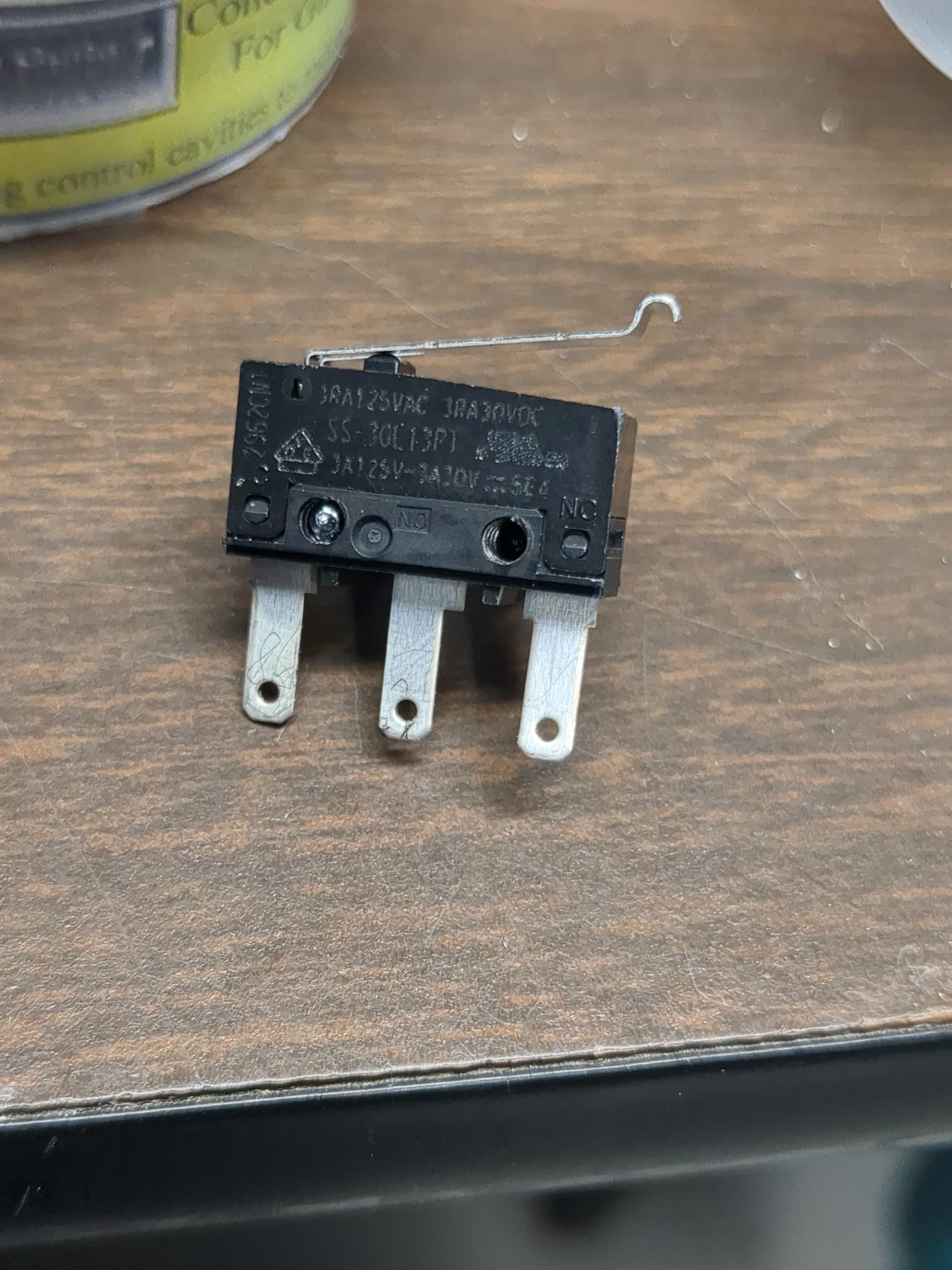
I’ve got the endstops and wiring from the V1E store. I see on the side of the endstop that there are terminals for C, NC, and O. The docs say to wire for NC - does that mean I should solder red to C and black to NC? If so, which one is ground and which is signal?
Yes.
For this purpose, it doesn’t matter which way round the the black and red are wired, as long as you wire them to C & NC.
If you were using a sensor with a 5v line, you’d want ground to go to Common and the Signal wire to go to the Signal pin. With a simple switch it doesn’t really matter, but if you’re considering changing to a different style of sensor someday, I’d recommend Common to Ground, and NC to Signal in order to “future proof” things.
I disagree here.
I would want no situation in which +5V could be connected to ground. The signal pin can be at logic high (+5V) or logic low (ground) but if you wire it that way, and connect the 5V line, then triggering the switch would connect +5V (NO) to ground (Common) Bzzzt. Pop!
As such, my switches are all connected with signal to Common(C) and Ground to Normally Closed(NC) in that way if I ever wanted to connect 5V for some dumb reason (Maybe all of my pullup resistors failed?) I could simply connect 5V to NO and call it done.
One thing you can also do with it this way is wire an LED+resistor between NO and NC. (Being careful of course not to replicate the problem that the SKR Pro boards had where you drain away too much potential. Maybe snap off any on-board LEDs) This will then light up at the switch every time the switch is triggered. NC will always be ground. NO will normally be floating, but will be raised to 5V potential when it closes with the signal wire (which will be raised to 5V potential when disconnected from ground by the pull up resistor) so the LED would light up then. So long as the current draw still keeps the signal line above the threshhold for logic high, everything works and you get blinky lights on the end stops instead of the control board.
You can also wire this with ground at common, by reversing the polarity of the LED, but it’s a less efficient circuit. The NO pin is floating, and then gets ground, while the NC pin is at logic low, then raises to logic high when disconnected.