The hole spacing for the endstop mount on the core measures in the order of 8.8mm (center to center) and I am wondering what model of Omron microswitch is supposed to fit these holes? It is definitely not the SS-5G type because that is what I have and they are 9.5mm centers. It is also not D2FC type because those are tiny and have 1.4mm holes and 6.5mm spacing.
The ones I have are from cqc and appear to have the 9.5mm mounting hole spacing, the same as the Omron SS-5G ones …They are screwed into plastic so close enough for the girls I go out with!
Considering the general level of precision for all of the printed parts, I am a little surprised by this hole spacing issue. After all a 0.7mm displacement of a 2.5mm hole is pretty big error, percentage wise, and would place undesirable force on the micro switch frame which could result in switch unreliability or even switch failure.
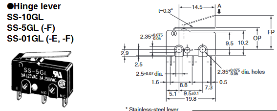
The other issue I encountered was that the mounting screws are specified as 2.5mm, whereas the holes in the SS-3G are specified as 2.35mm (+0.075, -0.05). I did have to drill a few of the mounting holes out to 2.5mm to allow a clearance fit for the 2.5mm screws whereas others where fine as is. Below should be a clip from the SS datasheet
I realise that this is all pretty trivial in the wider scheme, but I think we are dealing with a potential reliability issue here and that improvements are possible. I would have thought that if we are using SS series microswitches then the mounting holes need to be 9.5mm apart on the printed parts.
Is this measurement from the originating drawing, or did you measure it on a printed part? If the latter, then printing errors and measurement errors could account for the discrepancy (even with a set of digital calipers, it is not an easy thing to be truly accurate within 0.1mm when measuring holes center to center).
I am interested to know what the original mounting hole spacing is on the CAD drawings but so far do not have the skills to determine that. I do know that this error applies to both the Core print and the Yaxis Drive print. Also the Z Stop.
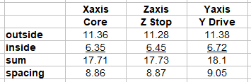
How I measured the actual printed hole spacing was by fitting a 2.5mm screw to each hole then measuring the outer and inner spacing using a digital vernier caliper and calculating from that. Results are:
But you can also see it by eye quite clearly, it is somewhere close to half the diameter of the hole.
I sincerely hope that this is not the result of printing errors because that would not bode well for my build and mean that my printed parts are 7% smaller than they should be.
If you subtract the outer measurement from the inner measurement, you will come up with the diameter of two screws.
So using the measurements that you provided, it shows that the Core screws are 2.5mm each, the Z Stop screws are 2.4mm ea, and the Y Drive screws are 2.3mm each. I’m assuming that you used the same screws for each measurement, so this sort of goes to my earlier comment that it is hard to be truly accurate when measuring fractions of a mm.
I wasn’t suggesting that your whole print is out by 7%, but when measuring tiny amounts , a little bit of offset or elephant foot or other print anomaly can throw your measurements off by a few fractions of a mm. Add the difficulty of accurately measuring things at that scale, and the likelihood that things are out by a few tenths of a mm is not overly surprising or concerning (at least to me, but I’m a noob at both printing and CNC.
I know that on my build, the PLA had enough “give” when attaching the switches that the screws went into the holes without any difficulty. I understand your point that the dimensions should be the same, but in life sometimes a fraction of a mm is close enough for what you need to accomplish.
Turns out that the CAD files have the holes for mounting the endstop switch at 9.0mm centers whereas the switch itself has 9.5mm centers. It looks like this discrepancy had been built in since the early days of LowRider3.
We also checked the scale of our print and found it to be correct so will just live with the issue and hope that it gets corrected at some point in the future.
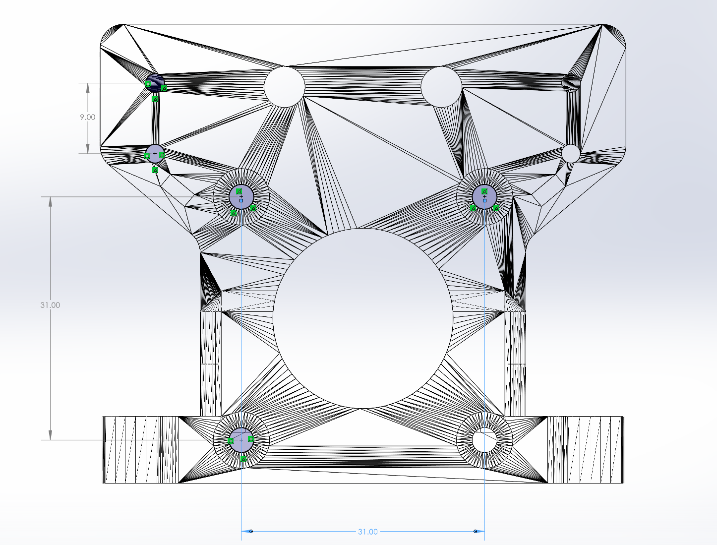
The image below is derived from the CAD for the Y Drive print and clearly shows the 9.0mm spacing for the mounting holes for the endstops.
I don’t think you should ask me. Today I was searching for a raspberry pi I know I have some where.
Haven’t found it yet, but found the bearings I was about to order for the LR3. Forgot I had ordered extra when building the Primo.
Reminds me of the reason tape measures are always so hard to find. Apparently, in the dead of night, or just when you are not looking, the return spring inside begins to resonate, as springs are liable to do, and allows the tape measure to levitate and move around. Hence why they are often difficult to find.
My solution is to always store a tape measure with the tape fully out and locked. This definitely improves the chances of finding it.!!
I used Solidworks to import the .stl file, created a sketch on the plane that’s parallel to that face, drew circles and then used coincident constraints (3 per circle) to align them to vertexs on the imported .stl.
In the past I’ve managed to make Solidworks import .stl files as solids and then do feature detection which results in holes etc. that can be dimensioned properly but for some reason I couldn’t make this one import successfully as anything other than the trangulated mesh that is what’s in the .stl file. That’s why it looks so crazy, that’s the actual content of the file.
I own three calipers, one decent, albeit inexpensive, metal one from Amazon, and two cheapo Harbor Freight plastic POS’s, none of which I can find… And I’d rather not speak of tire gauges, glove compartments, and center consoles.