How did you resolve the tension issue?
Tightened the tension bolts a little at a time like I described above. It eventually reached a good feel and I went with it. Everything seems to be moving smoothly, but I haven’t run it through any serious paces yet to try it out. That will have to wait until after dinner.
1 Like
With all the electronics hooked up, I went through the process of setting up the endstops and determining the offsets to square up the cuts. After tweaking the end stop locations, I was able to get the full 24"x24" range of motion. Final step for the night was mounting the new spoil board. With this, I should be ready to make sawdust tomorrow night!
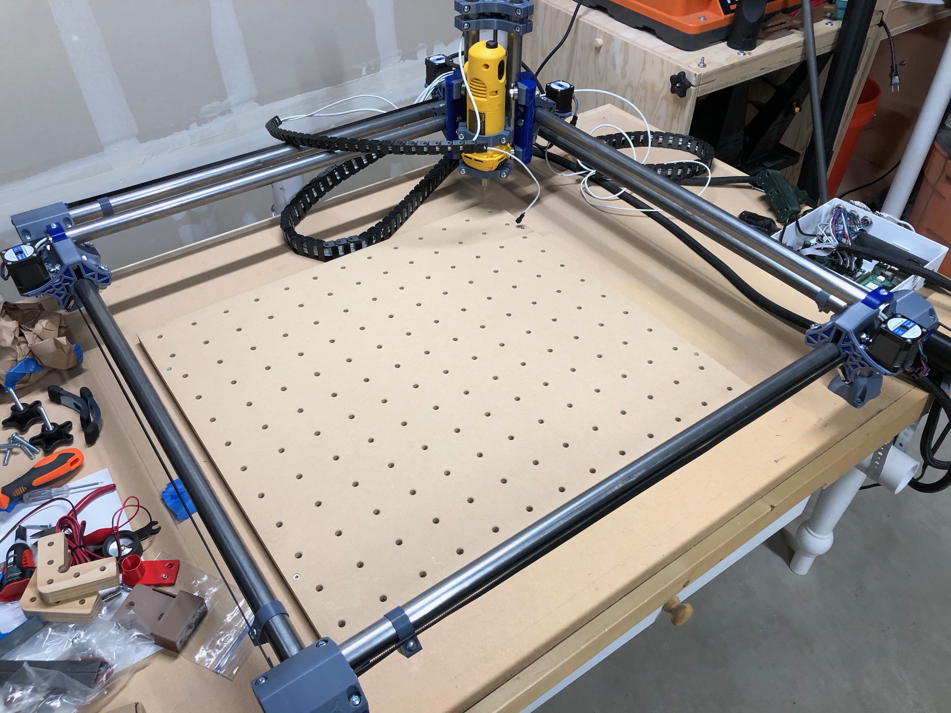
Obviously cable management is still an issue. But I have to figure out how/if the cable chains can be attached and still function with the limited space.
8 Likes
Sweeeeeet!
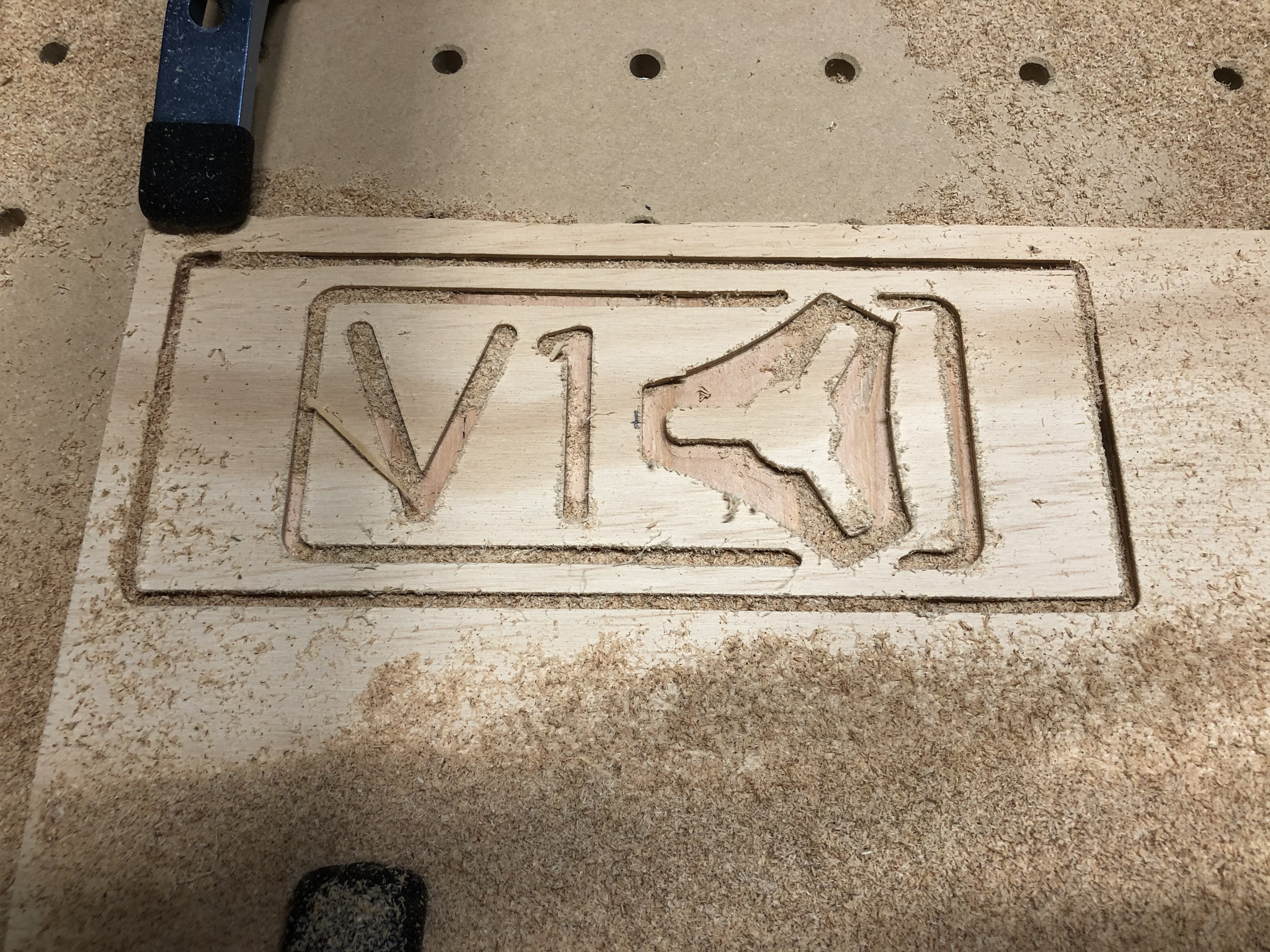
First Cuts! Made up a quick cutting job in some 1/4" plywood I had left over. The machine cut through it like butter, and now I have a sign I can mount next to my Primo so everyone knows who is responsible for this beautiful machine.
12 Likes
And for those of you interested, here’s a video of that first cut. This is real time with the default settings that I used for the Burly.

8 Likes
10 years ago if you said you could do that with plastic and pipes you would have been laughed off the internet.
Thank you Ryan
5 Likes
Still get laughed out of some parts of it…
2 Likes
To tru
I just did this as well…printing…
Been making wood chips today with the Primo. It’s been working great. Cutting the pine boards I’ve had the feed rate dialed yo to 300% and it has been chewing through the wood without a complaint. Clearly I need to fix the feed rates in Fusion.
3 Likes
That is what I like to hear, better than before!
1 Like
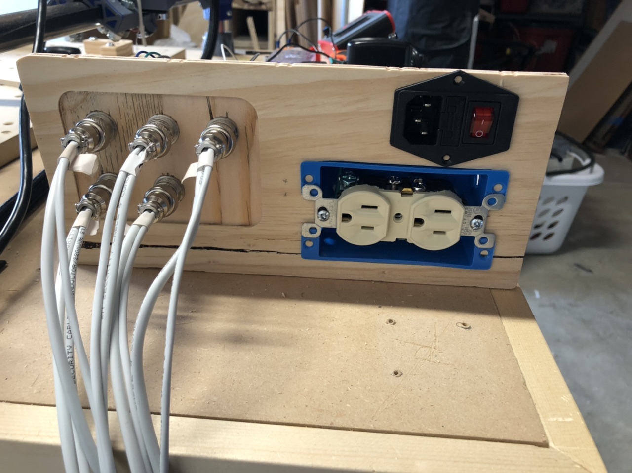
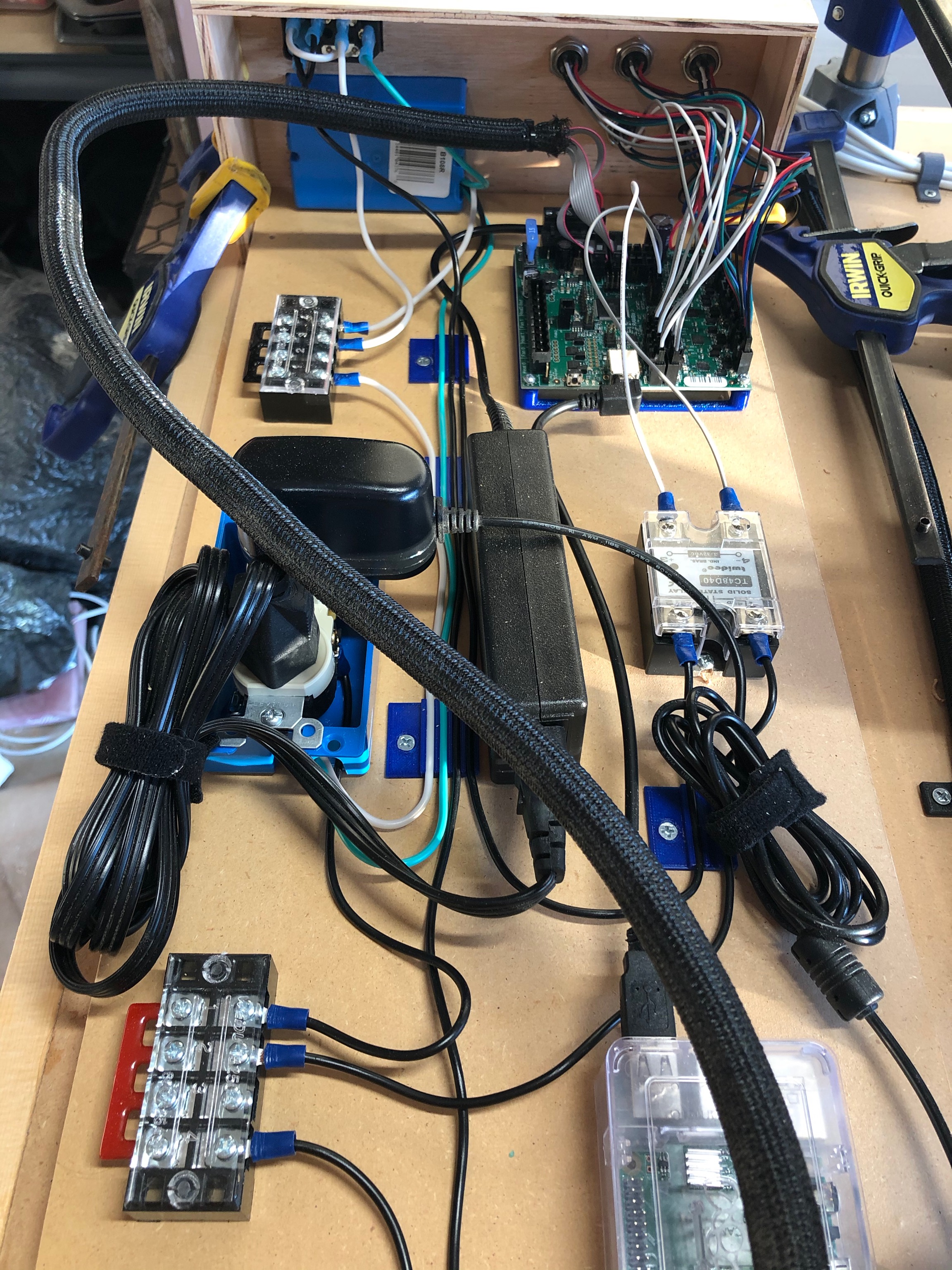
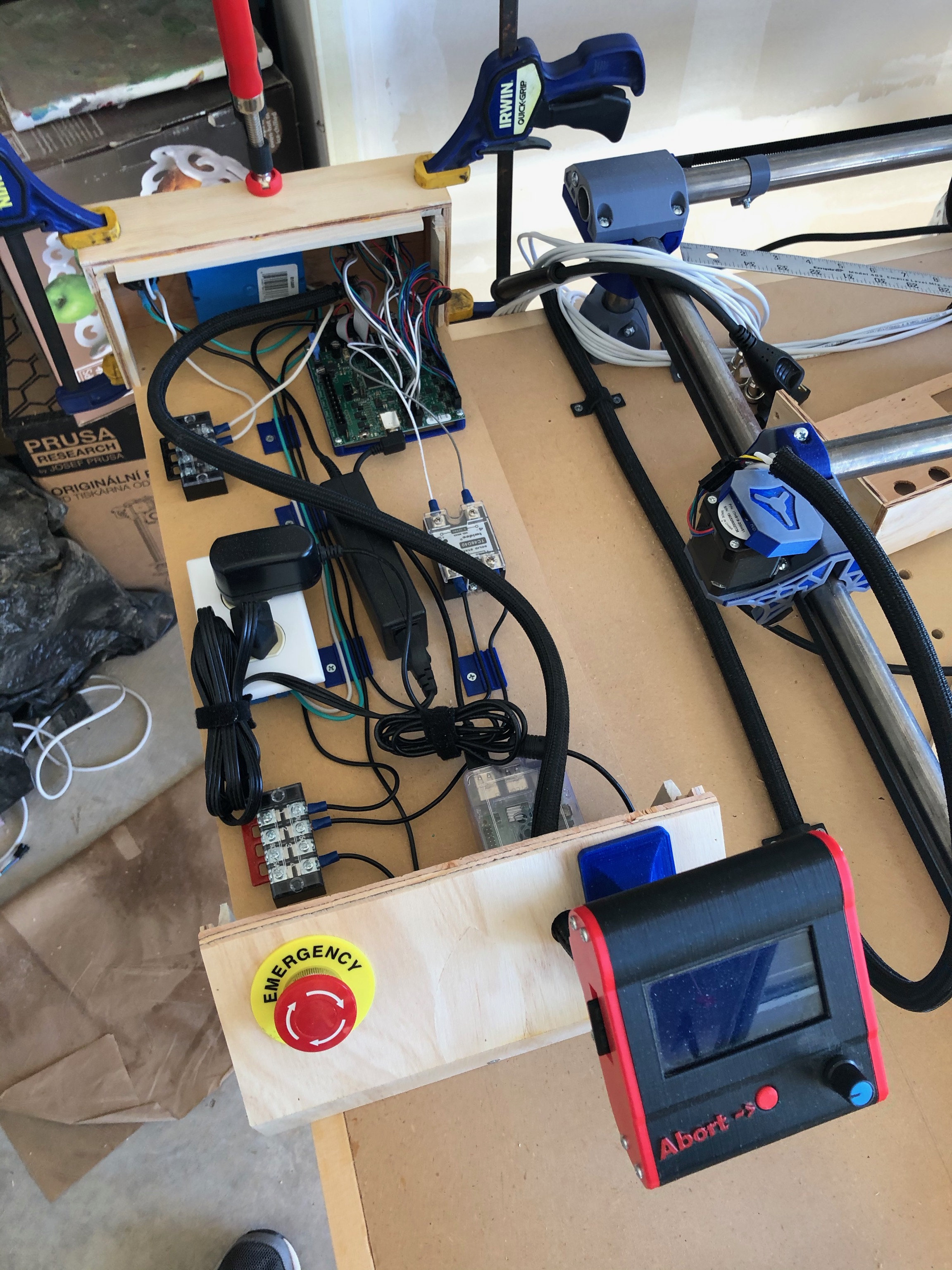
After proving that everything works, and getting a few production cuts done, I decided it was time to redo the wiring for everything. I unplugged everything, took the Rambo and RPi out of there case, and started wiring everything up on a piece of MDF. The goal is to ultimately build a case around all of the parts to keep the dust away, but first I needed to get the wiring sorted.
Finally used to the power inlet switch I bought from Ryan for the original MPCNC build and wired it along with the e-stop and Solid-State-Relay (SSR) into the outlets. One outlet is inside the box and wired to provide a place to plug in the Rambo and RPi power supplies. The other is at the box of the box and faces outside for the Router/Vacuum. It is wired through the SSR to allow the Rambo to turn the router on and off as needed.

I still need to design and print a stand off to hold the Rambo up off the board, and make a clip to hold the power supply in place. I have the case design in progress. Will need to use the MPCNC to cut out parts so that the aircraft connectors I used for the steppers and endstops can be attached. But I’m hoping to have the entires enclosure done by the end of the week.
7 Likes
Steps 2 and 3 of the re-wiring process are complete. Got the relay hooked up so that it will activate with an M3 and deactivate on the M5. Using pins 2 and 4 (ground and enable signal) of the Motex2 connector on the Rambo. Took a few tries to get the marlin settings eight so that the signaling was correct. Initially it was turning on on M5 and off on M3.
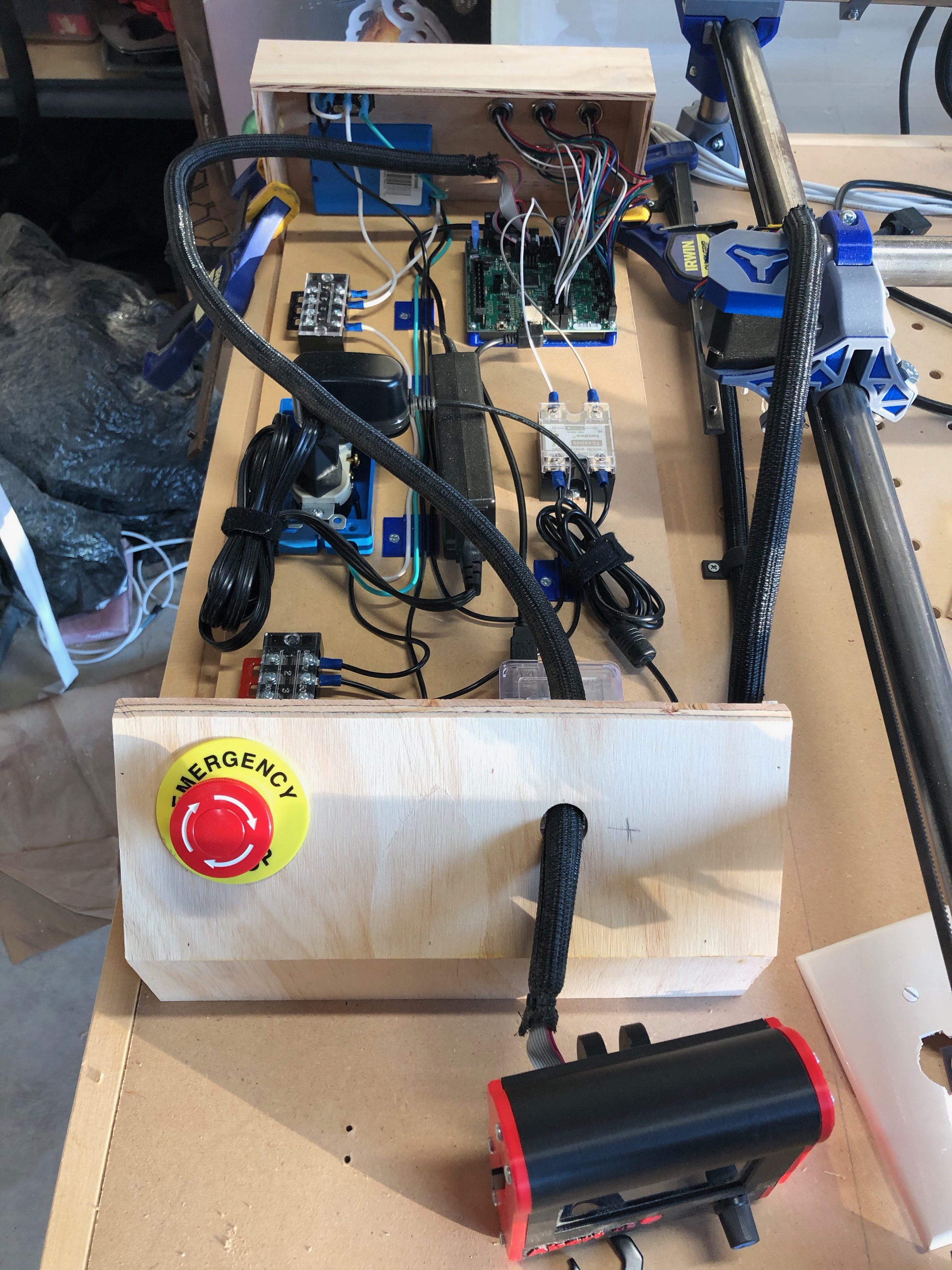
With that handled, I turned my attention to the enclosure for all of this, starting with the back panel. I didn’t realize until after I dismissed cutting that there was a tremendous amount of slack in the belts and looseness in the bearings. I could have sworn I tightened it all up the other day, but the whole core was rocking slightly, and half the belts were hanging kinda limp. That probably explains why the straight cuts were so rough, and why all the holes were 1-2 mm undersized.
Anyways, enjoy some pics of the current state!

5 Likes
I had the same problem. I noticed that between the time I first built the machine and when I went to face the spoil board that some of the belts were loose and two bearings weren’t touching.
I plan on checking everything before I cut for a while and see if it continues. I’m hoping things settle in after a few cuts like they did on the Burly.
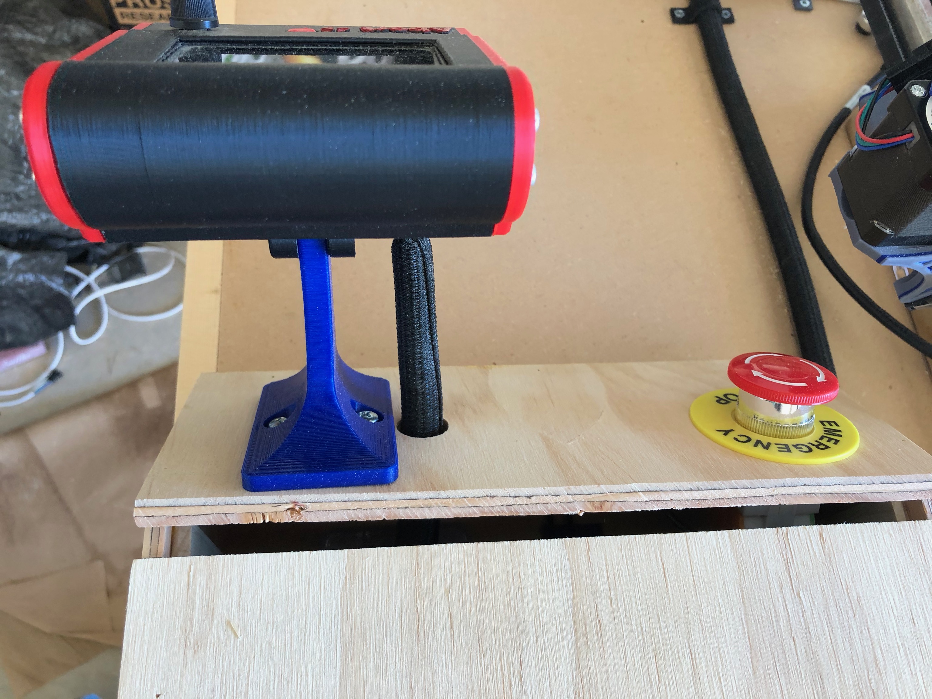
Work on the control box continues slowly. I designed and printed some wire clips to keep the electrical wires in the box neat. I also built the front portion of the case, including the mount for the E-stop as well as laying out where the LCD screen will be mounted.
The mount for the LCD screen is printing now. Once it is mounted, I’ll start focusing on getting the main top assembly finished so that everything is covered and protected from dust. Only thing still to figure out at this point is airflow and cooling.
4 Likes
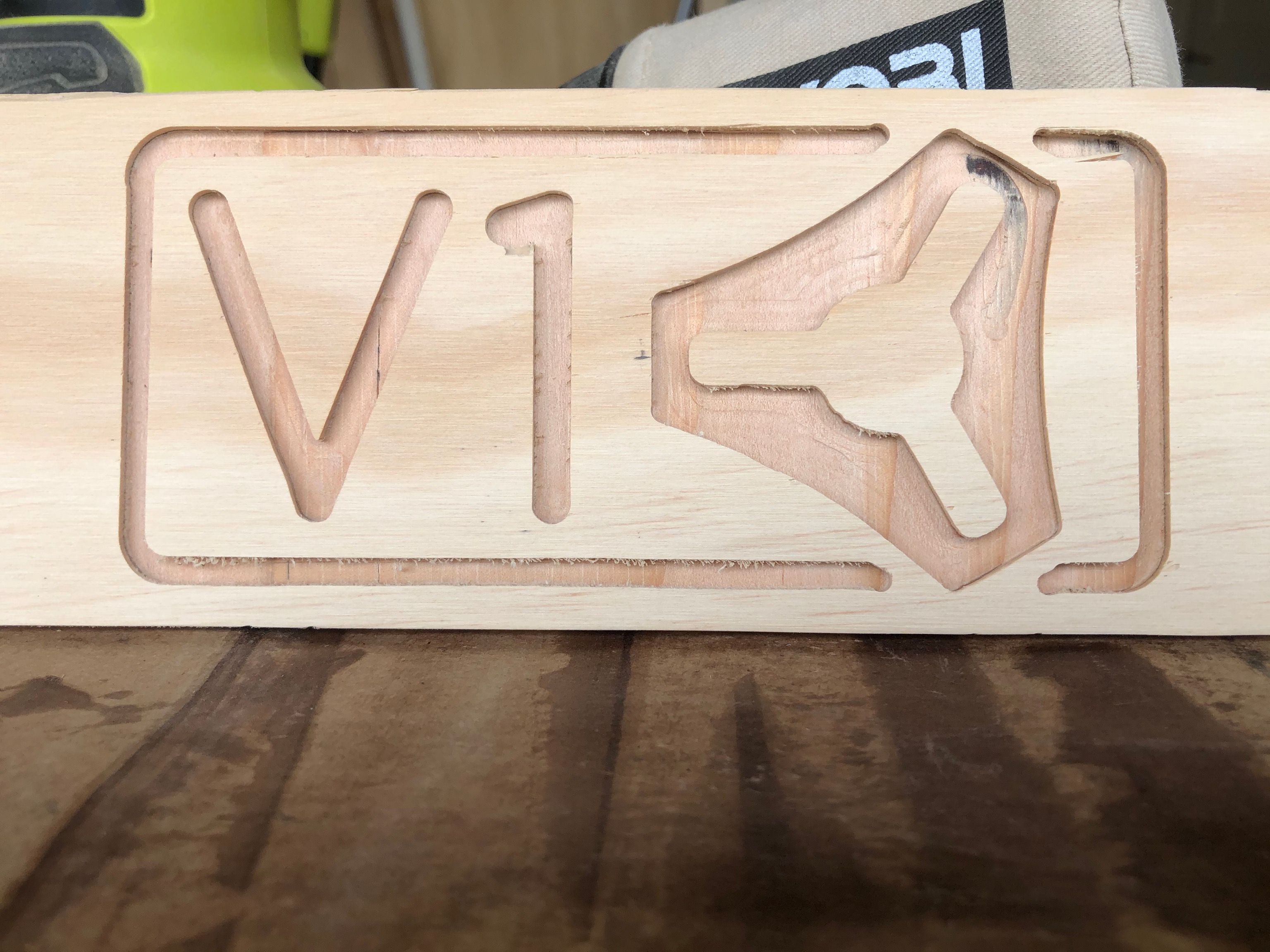
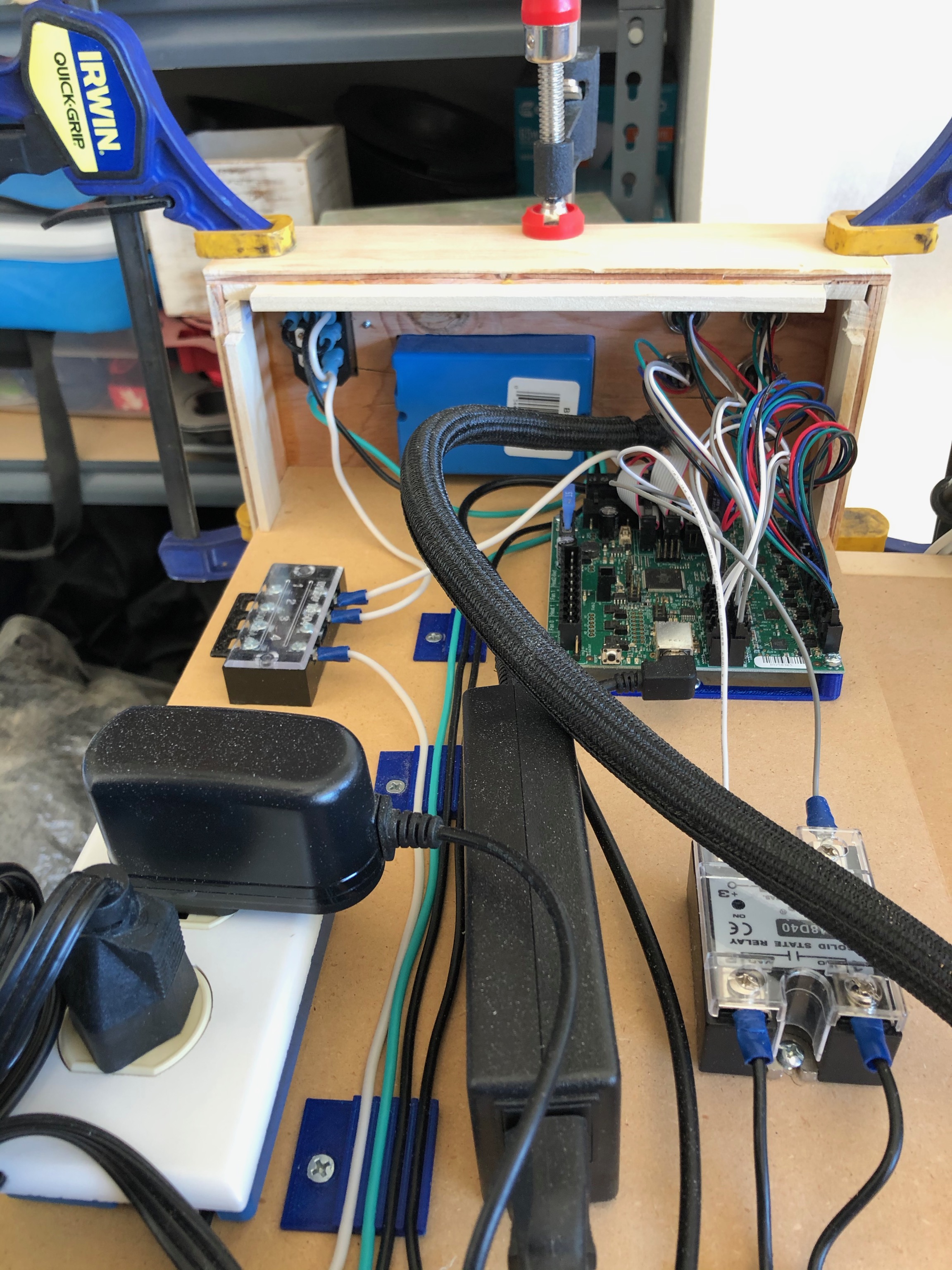
Spent the day finishing up the control box. Had some spacing issue on the backplate between the power inlet switch and the outlet box, so I rebuilt the back end of the box. Moved the outlet close to the middle, and left more room for the inlet and switch. And, since I tightened up all the belts and re-tensioned the core, the result was way better than the previous attempts.
This job took about 13 minutes to cut, and only about 10 minutes of sanding to cleanup all the fuzzies. Aviation connectors fit like a glove this time, and the opening for the electrical box only needed minor adjustment with the box cutter to clear out some cut cut pieces.
For anyone keeping score, I have fusion setup to use the 3mm (not 1/8" like it claims on the package) bit and run it at 1000mm/min (~16mm/sec) with a 6mm DOC. The trochoidal clearing of the connector recess isn’t nearly that fast because of all the ups and downs of the Z-axis, but once it starts cutting the holes for the outlet, switch, and the outside cutout, it flies. Only artifacts of that speed are the slight divots where it stops to leave the tabs.

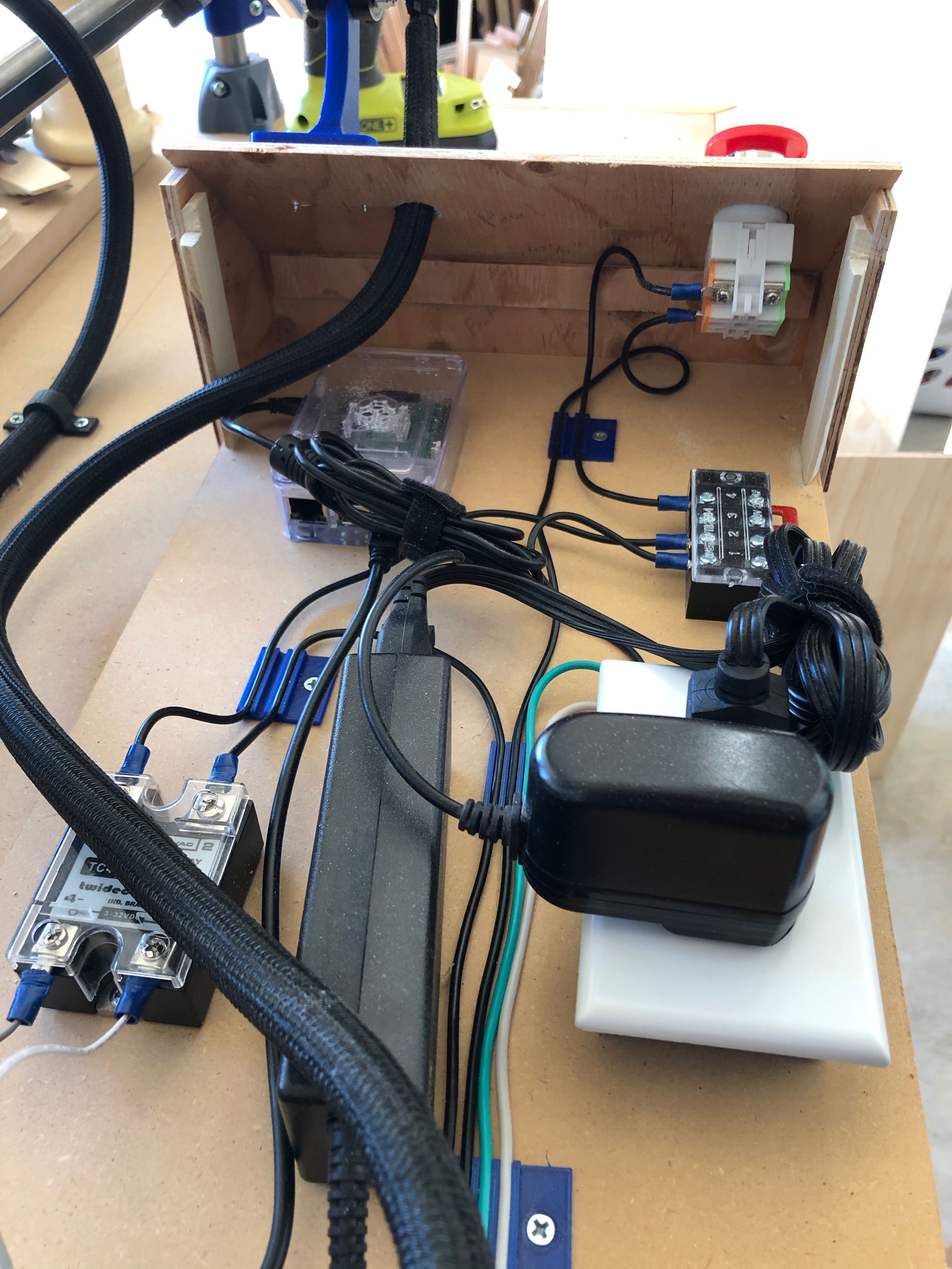
Next up was building the top cover to enclose and protect all the electronics. There isn’t any ventilation in the box at the moment, but I haven’t quite figured out how to add it without allowing all the saw dust and wood chips to also get inside.
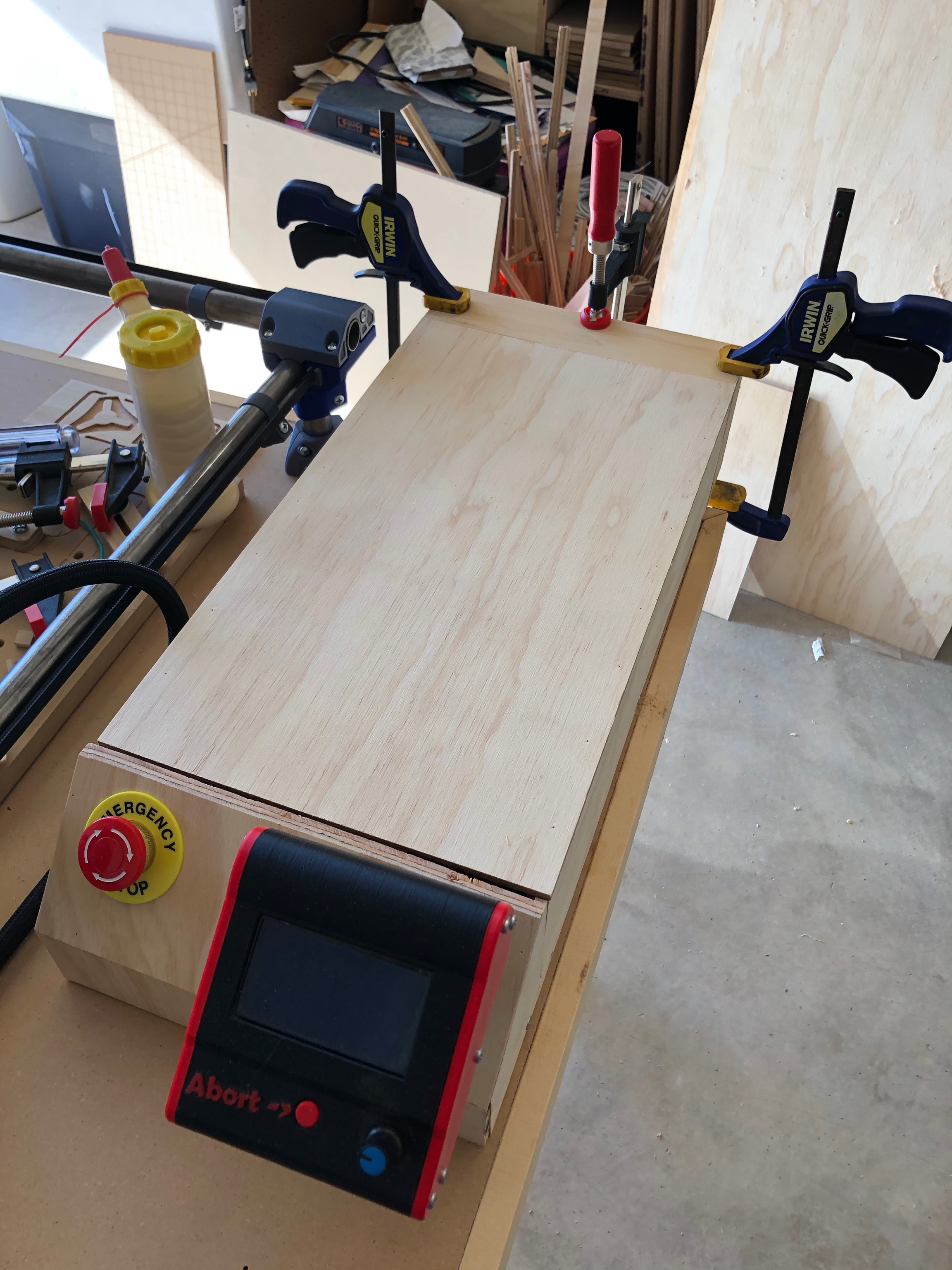
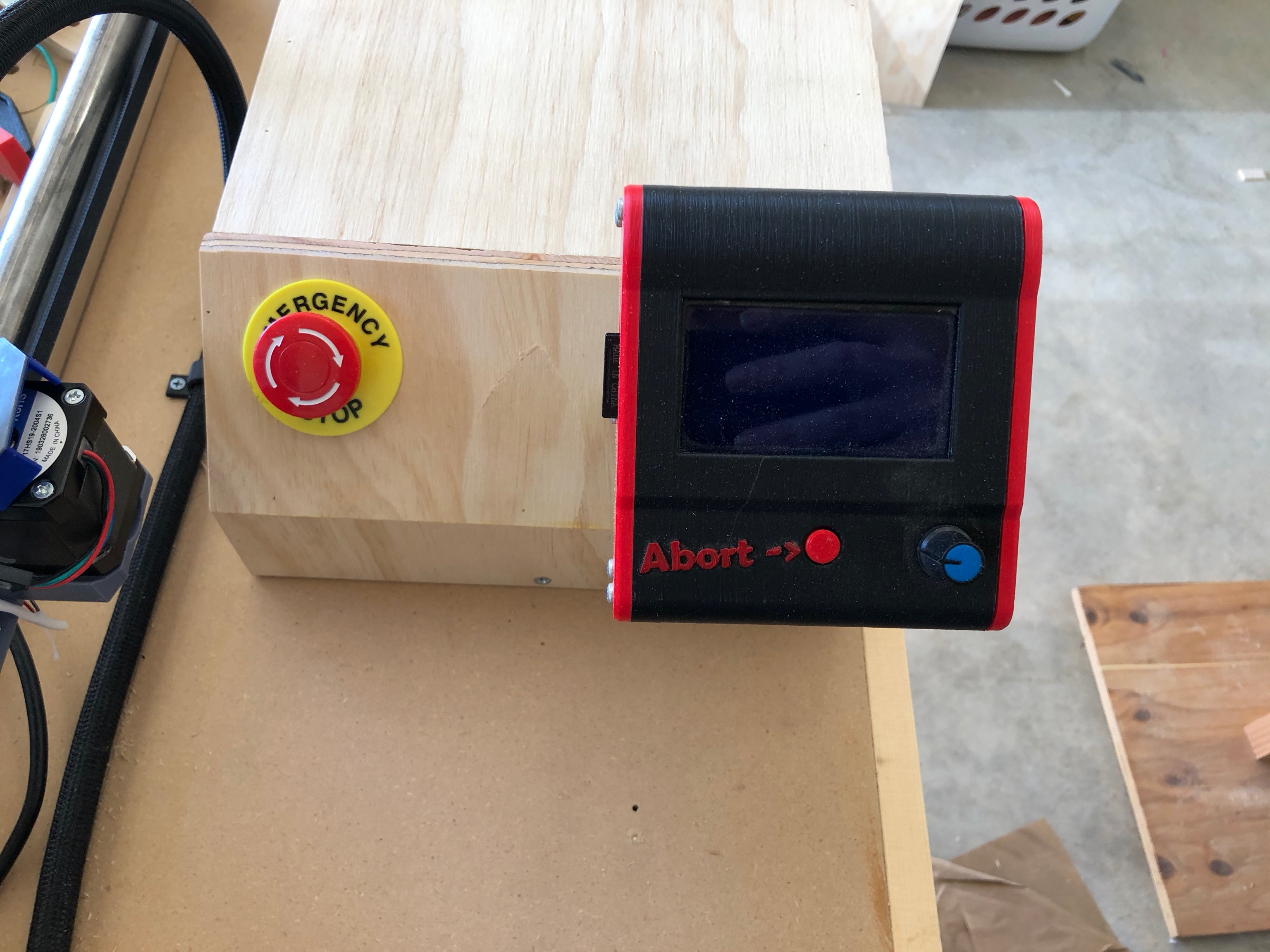
I printed out the mount that goes with the old display holder from my Burly and mounted it on the front. I was concerned about the size of the mount and how far out it pushed the display, but in practice is has worked out well.
Inside the box, everything has been attached to the base except for the power supply for the Rambo. Printed a custom mount for the Rambo to allow me to attach it to the base along with cable clips to route all the 120V wiring through the case and keep things clean.
In the final layout, the Rambo is in the back right next to the back plate to shorten the mess of wires that connect the stepper drivers and endstops to the aviation connectors on the back.
In front of that is the Solid State Relay that controls the two outlets on the back. The router gets plugged into this to allow automatic control. Once I figure out how dust collection is going to be handled, I could use the second outlet to have the vacuum come on at the same time as the router. I just need to figure out if the circuit can handle the surge of both those devices powering on simultaneously.
On the back left is a terminal block for the neutral side of the 120V. It connects to the power inlet and both electrical boxes.
In front of the neutral block is the internal outlet. This is where the power supplies for the Rambo and Raspberry Pi are plugged in. It powers up as soon as the power switch on the inlet is turned on (assuming the E-Stop isn’t pushed).
In the front right is the Raspberry Pi running V1Pi. It is hooked up to the Rambo and my Wifi so that I can connect to it and control the CNC from a laptop when necessary. I need to find a way to use it to flash firmware to the Rambo so that I can compile on the computer, then upload and flash without having to disconnect the Rambo and drag it and it’s power supply inside to update it.
On the front left is the terminal block for the 120V hot side. The Hot side comes in through the inlet, runs the length of the box through the E-Stop, then into the terminal block. From there it is connected to the SSR and then to the outlets on the back. It is also connected to the internal outlet.
A lot of words to describe everything. If you have questions about anything, let me know.
5 Likes
This is really cool! I need to figure out all of this stuff…
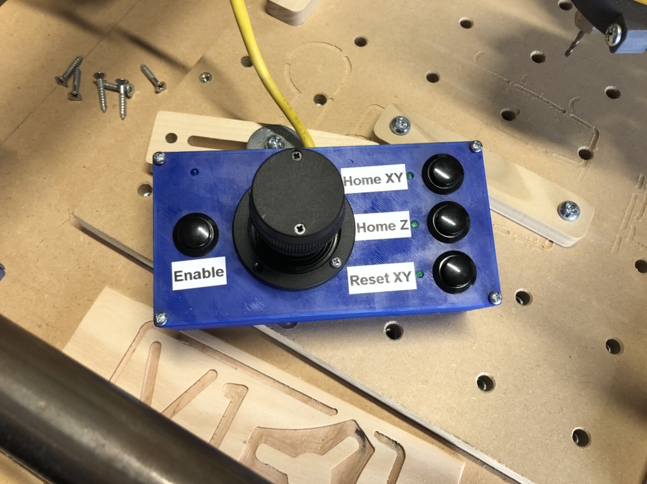
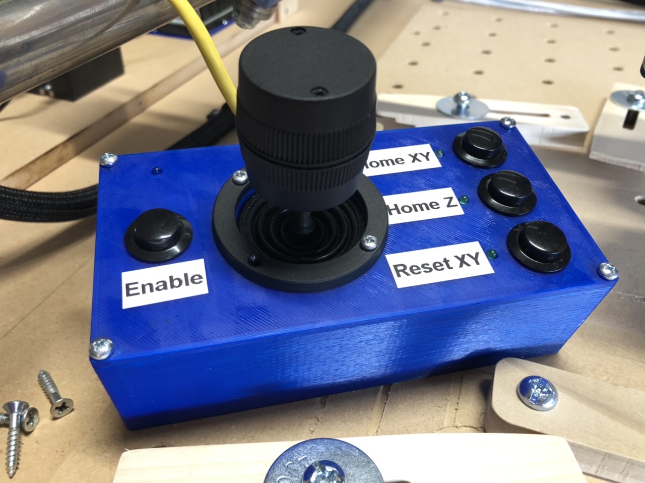
Finished up the Position-o-Matic 3000 for my MPCNC. The three buttons allow you to home XY, home Z, and zero the XY axes.
It works great. It will definitely make the setup process of zero I out the CNC faster than using the screen.
6 Likes
Ok. Now redesign the lid and embed the text into the print instead of the labels 