That is looking real nice, almost Lowe’s Kobalt colors if you are trying to color match your shop.
I have to say, seeing all the new Primo parts coming out is very refreshing. I have seen what seems like millions of Burly parts. These look even better to me.
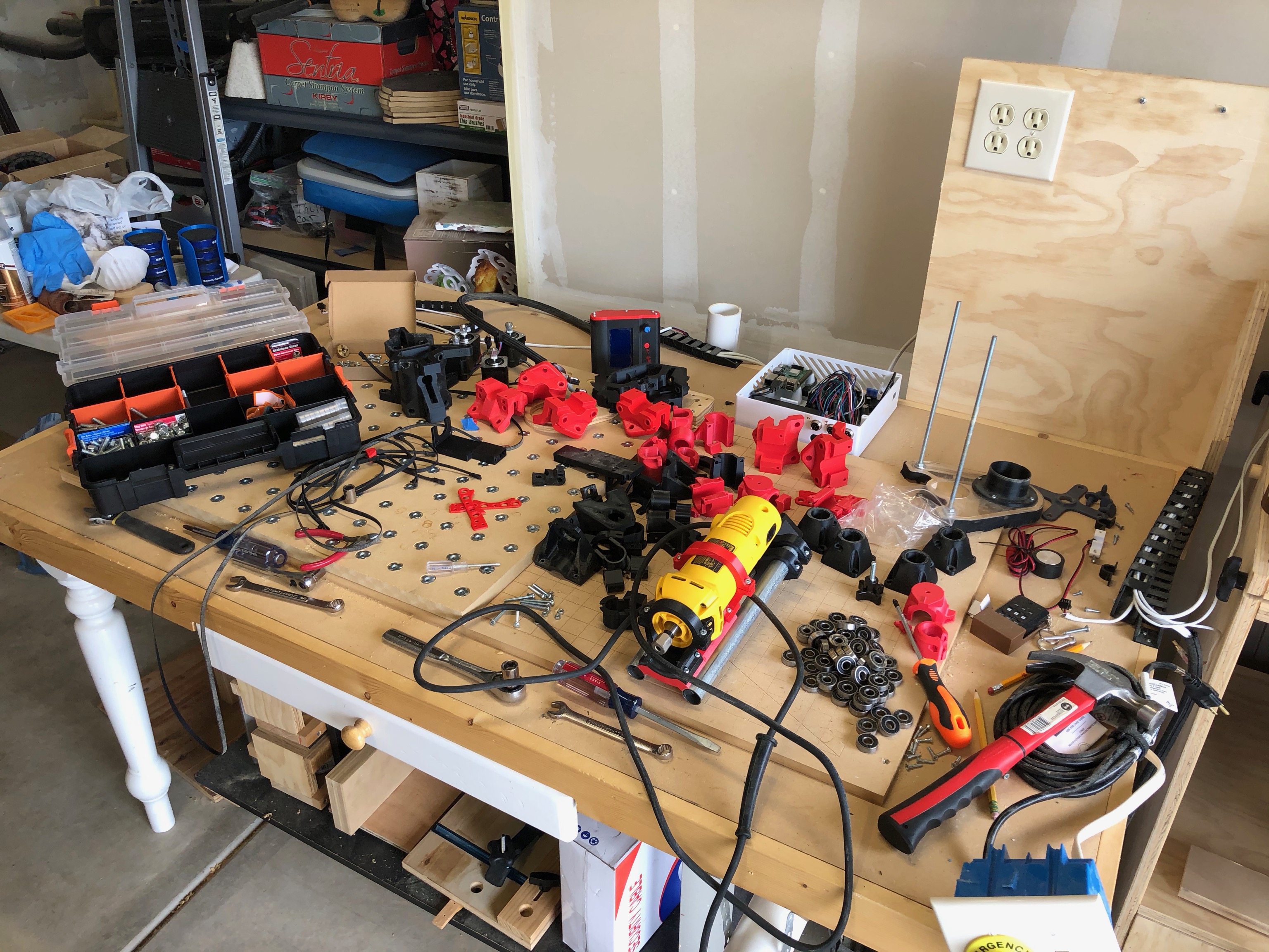
All the parts have finished printing (except for the z-axis hole jig) and I’m starting the assembly process. So far, I have pre-cut threads in all the nylocks, cut all the tubes to length, put the tubs on the belt sander to put straight ends on them, and pre-assemebled the M5 screws and lock washers onto all of the parts where it makes sense.
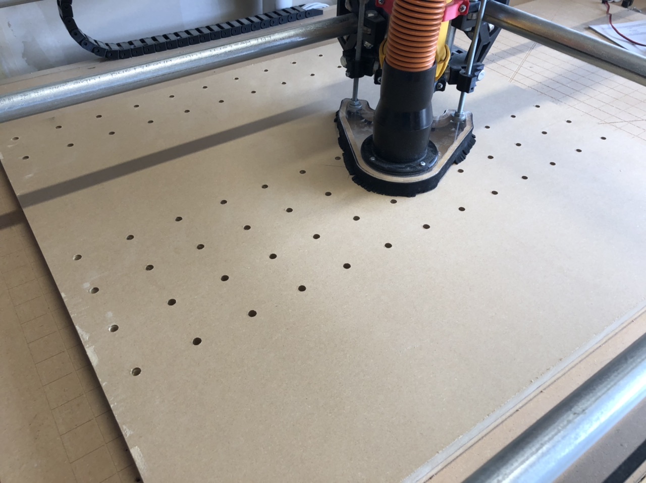
Next step is going to be getting the new spoil board setup on the Burly to try to get all the holes cut for the hold downs. Unfortunately, the Burly doesn’t have quite enough travel in the Y direction to cut all the holes, so I’ll have to drill the last batch of holes by hand.
So… I forgot when I started cutti N.C. the spoilboard that one corner of my burly had slipped and was lower than the rest. So I ended up with 2/3 of the holes not cut through, and most of the counter bites not being deep enough for the t-nuts. Looks like I have some manual drilling ahead of me. Le sigh.
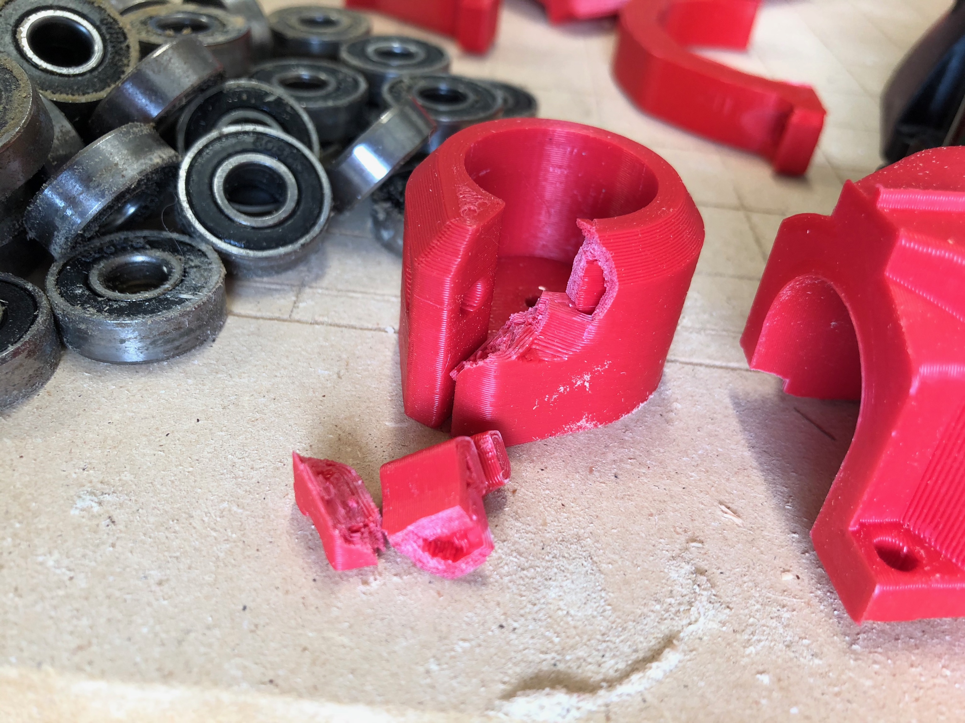
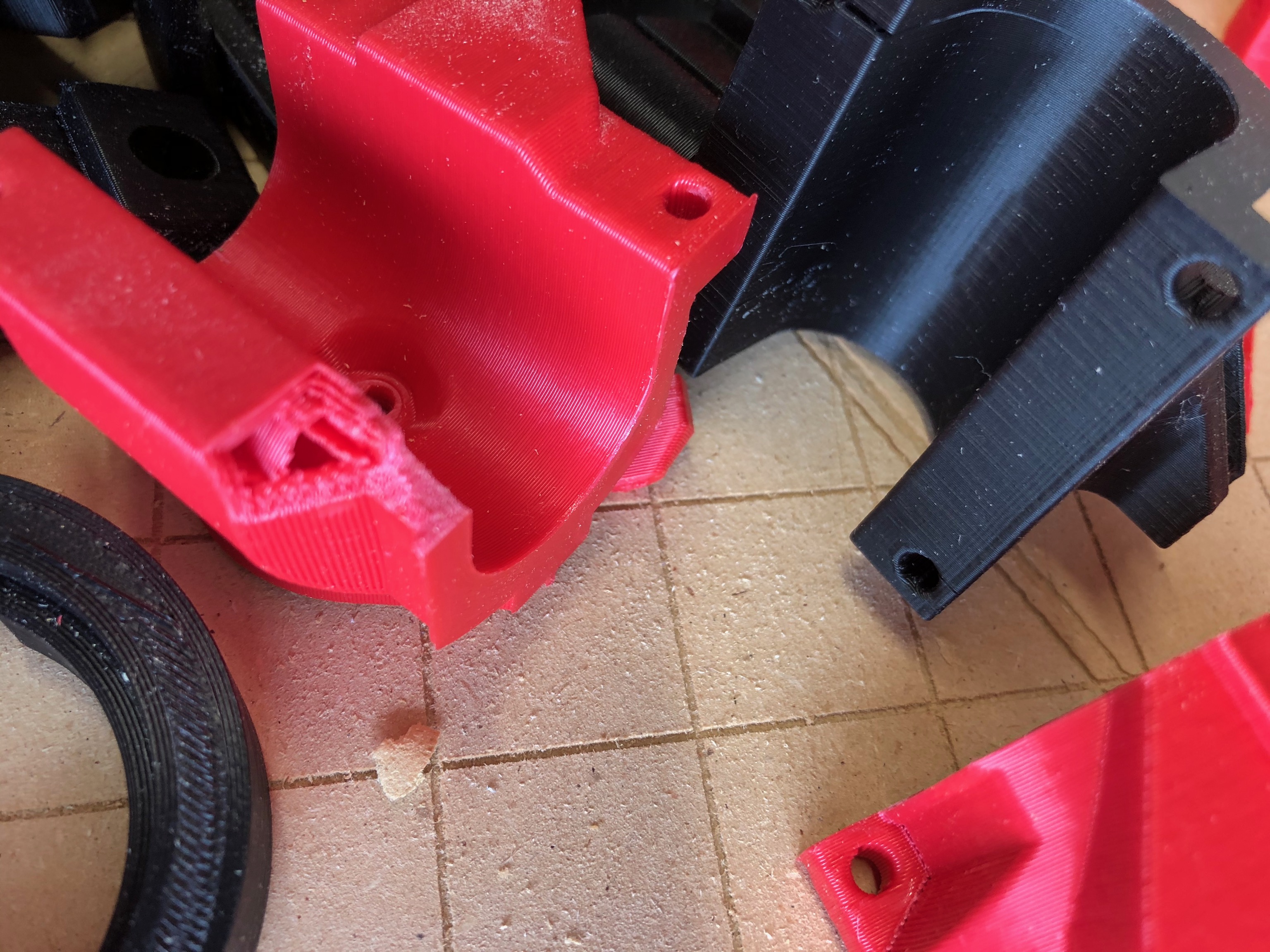
Working hard on assembly today. But first comes disassembly. Spent the morning taking the Burly apart and recovering all the bolts screws, nuts, and bearings. It was a little sad to see it go. But, on to new stuff.
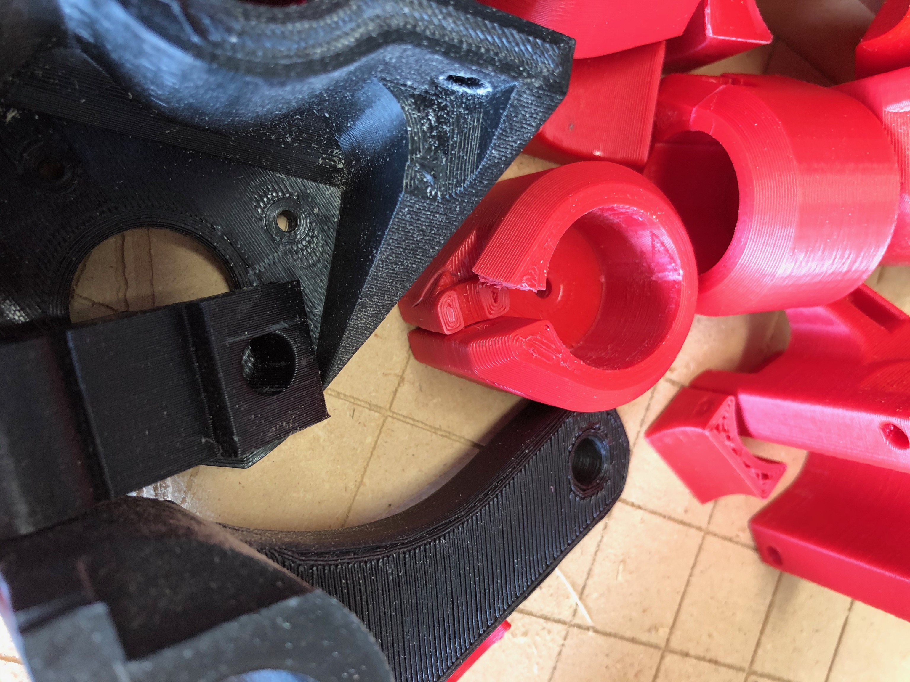
Decided I can’t resell the printed parts as I go too He-Man putting some of the screws in and ended up breaking quite a few of the parts. Not to mention the cracks that had developed in the trucks.
Let this be a warning to those building this thing: Take it easy on the tightening! I’ve been much less ham-fisted during the Primo assembly.
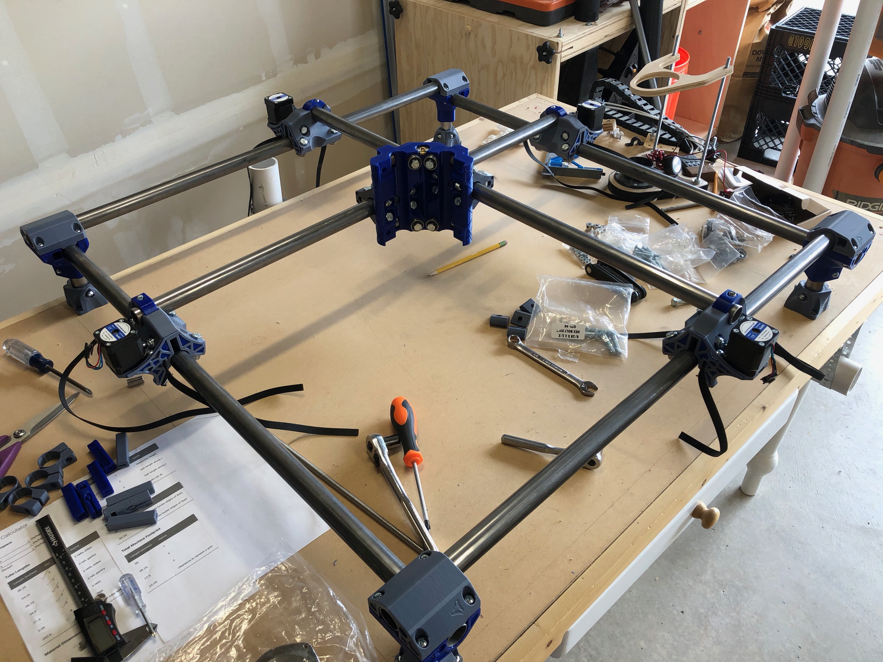
With the old Burly resigned to the recycle heap of history, I started in on the Primo build. Took my time getting the base frame as square as possible. I think I’m within 1/32" (i.e. <1mm) corner to corner. Worked my way through the assembly steps with help from my dad and we made good progress on assembly.
Made it all the way to Z-Axis assembly before I ran into trouble with the instructions. It took me 15 minutes to realize that the reason the DW660 mount wasn’t attaching the Z-Aix correctly was because I hadn’t printed the tool mounts! I guess in all the discussion I read, I misunderstood that the mounts require the tool plate. I guess assembly will have to wait until tomorrow evening.
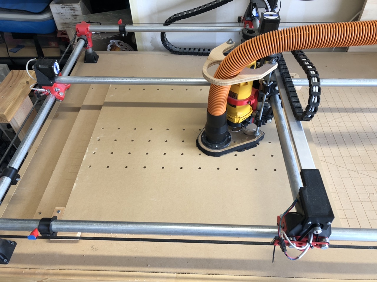
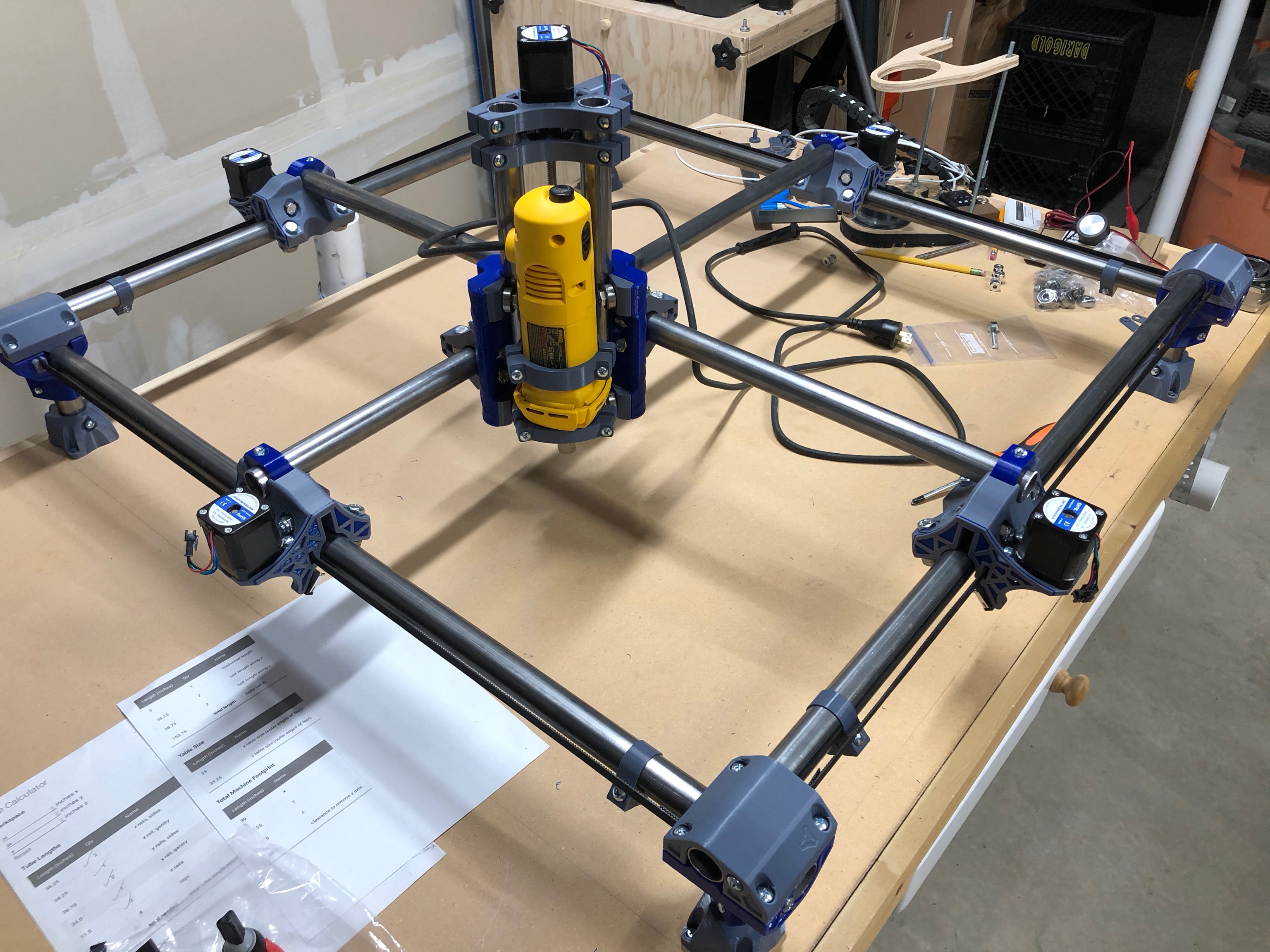
So tonight’s movie was shorter than expected, so I was able to get back out in the garage with the freshly printed mounting plates and get the Z-Axis done, plus get it mounted and the belts tensioned!
I have a weird issue though. The core is racing up and down around the y-axis. Not a lot, but enough that it would cause inaccuracies out at the end of the tool. @vicious1, any suggestions on what might be causing it? It’s as if the top and bottom bearings on X-axis rod aren’t in contact with tube.
On a side note, Did you miss the instructions about rotating the shroud on the Dewalt? It’s to spin the power cable away from the Z axis so that it doesn’t bind on the core.
If the gantry clamps are not making good contact with the rail. First question, did you tension the tension bolts? If you did and the rail is still loose. Take the rail out, loosen the two non-tension gantry clamp bolts, then tighten them back up (or even add a little tension and tighten them).
I believe there is a note about this in the instructions?
Or if you mean the trucks can move while not powered, yes, they move more than the old ones but should spring back.
I took a quick video to show the looseness I’m referring to. As you can see in the video, one side can be lifted and down, but the other side cannot.
Ryan, are you referring to the tension bolts on the Core Clamps? I did try tightening those up, and it didn’t seem to make any difference. I am resting the bearings from the old Burly build, so I may try pulling the clamps off and changing out the bearings so something a little cleaner.
@jeffeb3 I’ll have to read back through that section and make sure I’ve got everything setup correctly. At least the core is easier to get off in this build. +1 for not having to remove the belts and steppers to get it off.