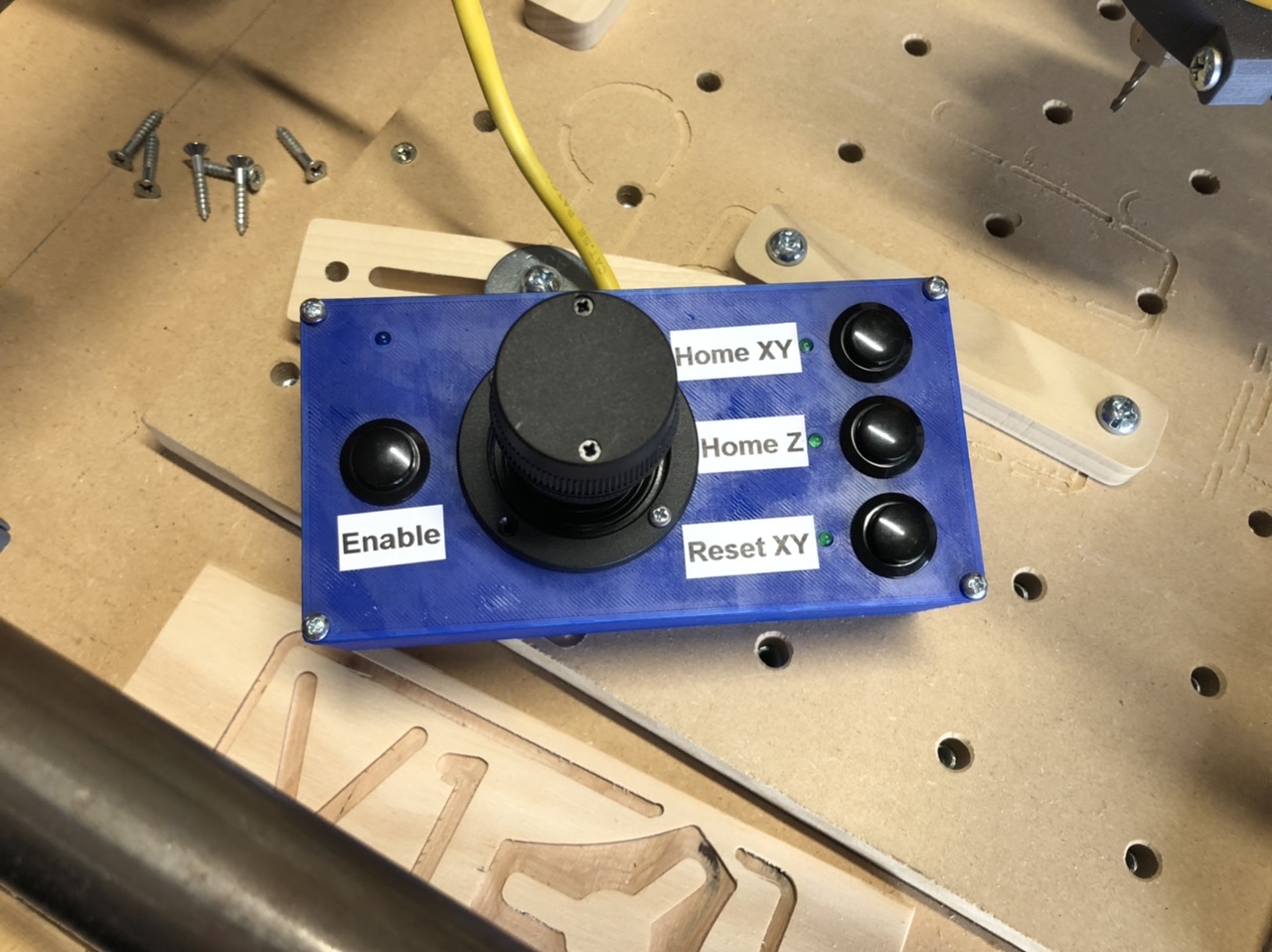
Finished up the Position-o-Matic 3000 for my MPCNC. The three buttons allow you to home XY, home Z, and zero the XY axes.
It works great. It will definitely make the setup process of zero I out the CNC faster than using the screen.
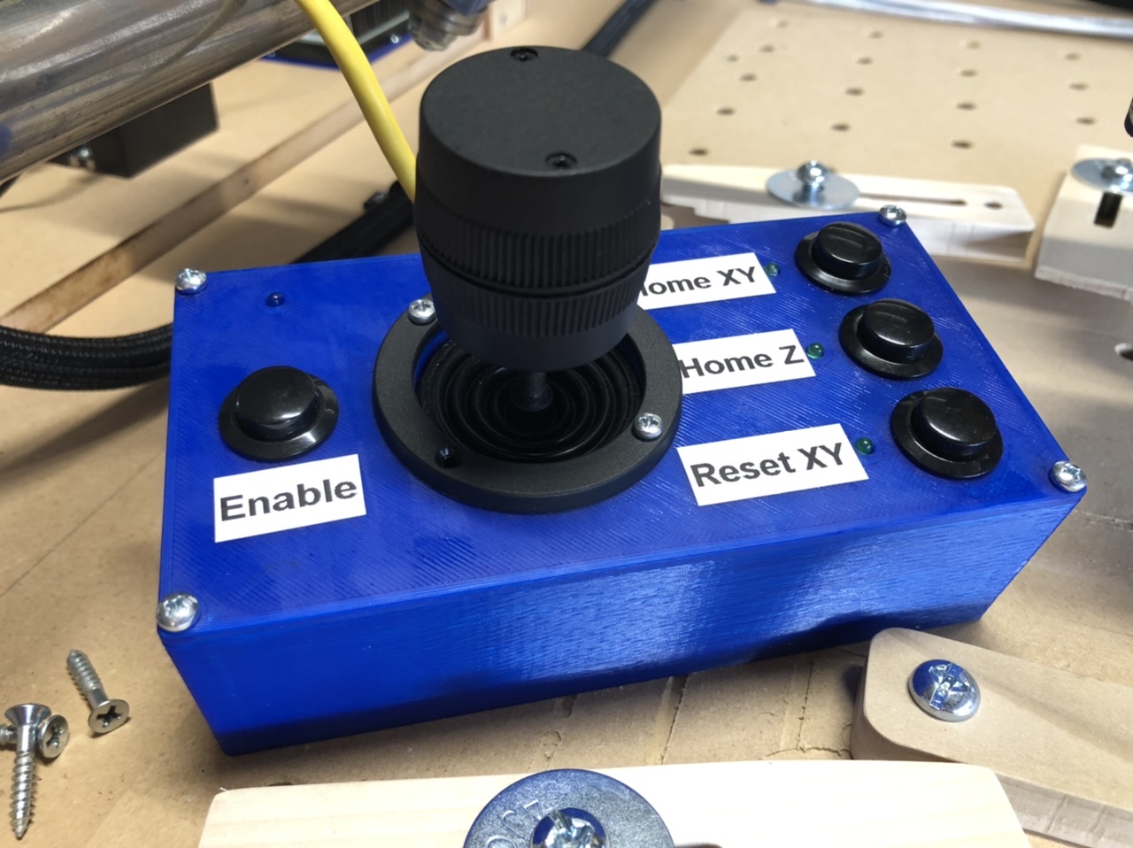
Finished up the Position-o-Matic 3000 for my MPCNC. The three buttons allow you to home XY, home Z, and zero the XY axes.
It works great. It will definitely make the setup process of zero I out the CNC faster than using the screen.