")
Previously (about 10 or 11 days ago) I posted a video about tramming the gantry (and also mentioned that the same software method could be used for squaring the table/machine as well). That video was titled “LowRider v3 CNC - Tramming & Squaring with Jackpot controller”:

Well, today, I finally got around to finishing the process of squaring up my table — since having switched to the Jackpot board (previously used an SKR board).
Last time I squared my table (while using an SKR board) I had used software (the “M666” G-Code command). See this earlier video for details on that:

This time I wanted to physically square it by using my adjustable end-stops.
I got it squared — wherein my “diagonals” are each measuring at 2720.25 mm. I estimate my margin of error is +/- 0.25 mm.
I could have used software again, yet this time on a Jackpot board, that process would be by editing the GRBL feature known as “pulloff_mm” which is an editable value attribute of each given axis, edited within the config.yaml file.
Since I used physical adjustments to square, I don’t need to edit my config.yaml file.
Regarding the latest video (top of this post) showing details on squaring with the Jackpot:
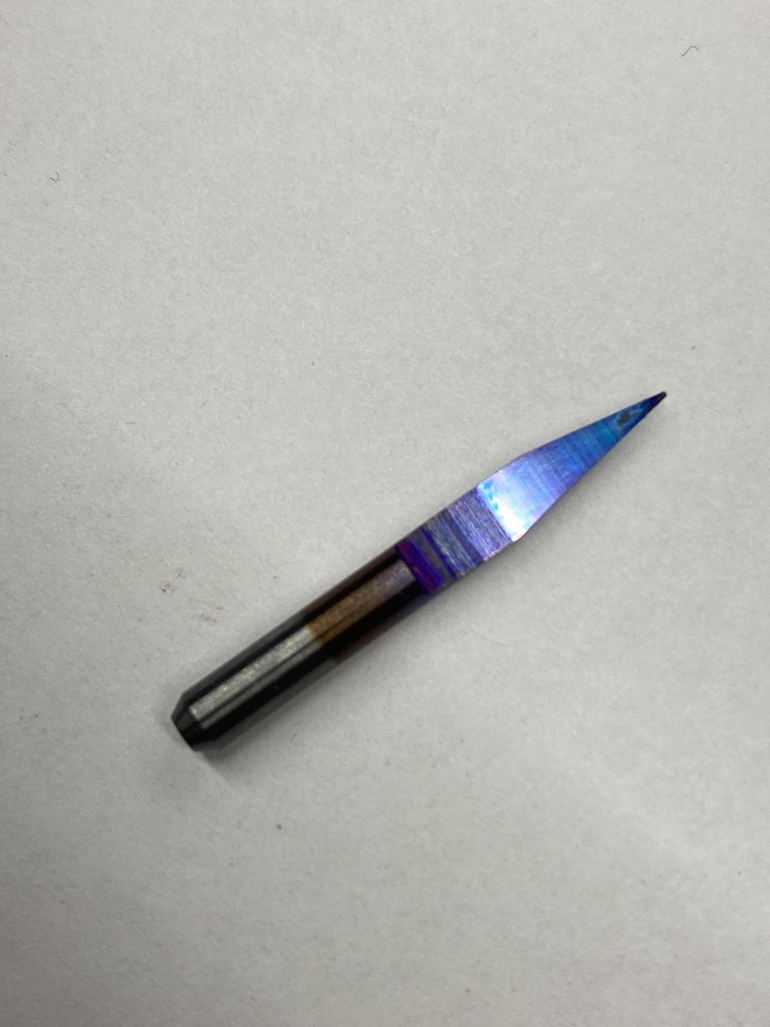
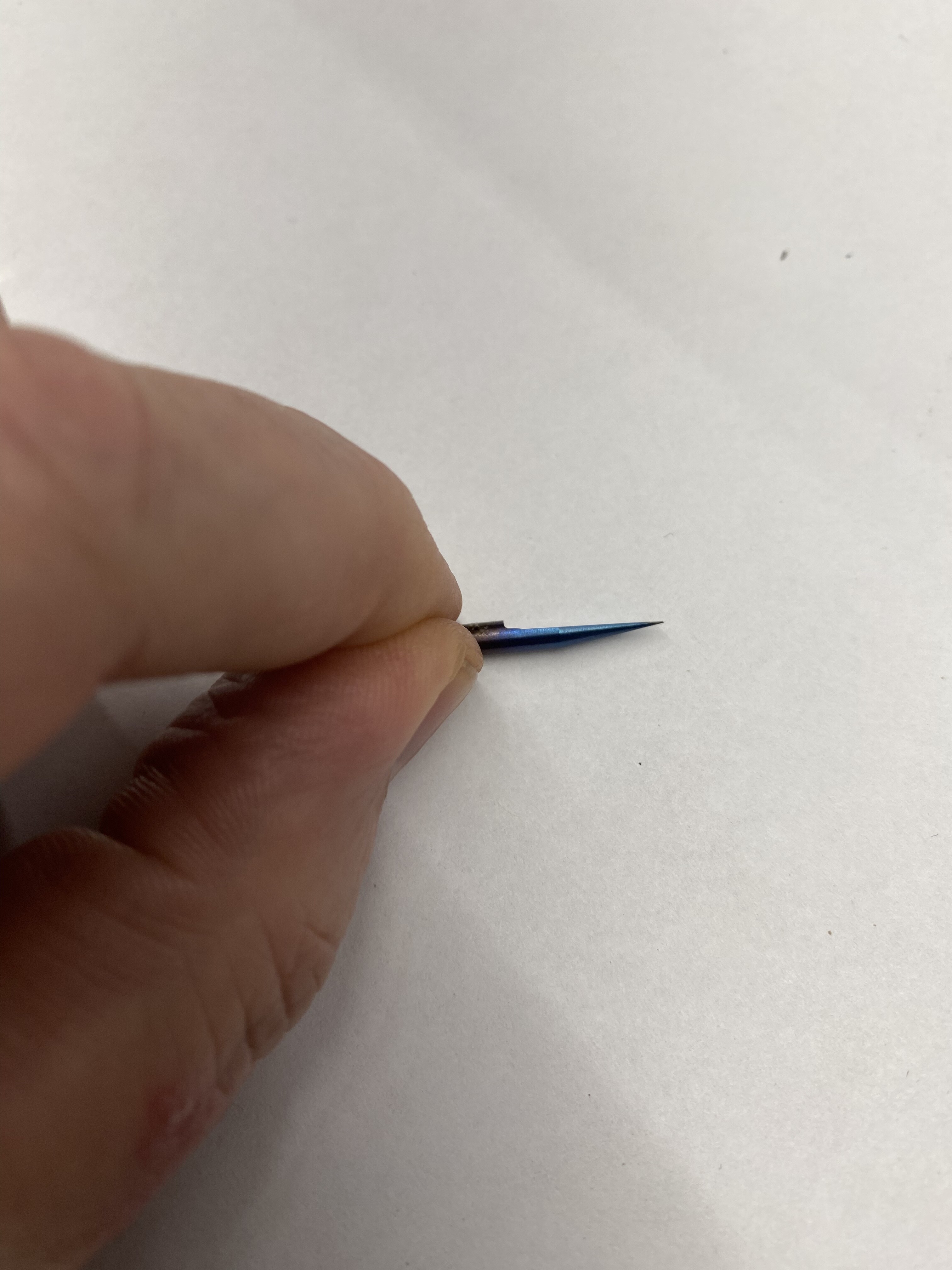
Here’s a great V-bit from the V1E.com shop: 1/8" 45 Degree Carbide V-Bit – V1 Engineering Inc
PROBING SCRIPT shown in video:
For clarity and convenience, I’m using my Jackpot with hard limits enabled and soft limits enabled, and my table size included in my config.yaml file, and the following is the exact script I’m using for my Probe macro (except I have the M0 commands commented out by starting those lines with a semi-colon, and I also don’t use the last line for spindle start):
G21 (MSG G21: Metric mode)
G90 (MSG G90: Switching to absolute positioning)
G94 (MSG G94: Feed = per minute)
G92 X0 Y0 (MSG G92: Setting current XY position as workspace origin 0,0)
M0 (MSG Attach probe)
G38.2 G91 Z-124.9 F400 (MSG G38.2: Fast probing to material)
G1 Z5 F400 (MSG G1 move Z up by 5mm, speed 400)
G38.2 G91 Z-6 F100 P0.34 (MSG G38.2: Slow probing to material. Plate thickness: 0.34)
G90 (MSG G90: Switching to absolute positioning)
G1 Z30 F900 (MSG G1: go to Z30, speed 900)
M0 (MSG Remove probe)
M62 P1 (If used start spindle pin27)
ALSO NOTE: For this video, for use of the “squaring” script, in my probing script, I have the “G92 X0 Y0” line commented out (starting it with a semicolon), and my “squaring” script is programmed to use the Machine’s homed 0,0 origin. You can program yours to base on a workspace offset origin if you like, just be aware of how you’re doing it.
Re. SQUARING SCRIPT:
V1E docs with full details for SQUARING: LowRider CNC V4 - V1 Engineering Documentation
…which includes JAIME’s TOOL for creating various scripts, including for drawing “L” with a pen in corners for checking for square: G-Code Test Pattern Generator
My script shown in the video did not come from there. See below.
(NOTE: I looked at Jaime’s script creation tool just now, and noticed that its “Squareness marks” feature seems to be focused on making pen marks (in “L” shape) instead of dropping the sharp V-bit to make a hole. I looked to see if another feature of the tool could do this, and did not seem to see anything. I may have missed it. So, editing my script may be something to try after all.)
; ( GCode Macro Script by Doug Joseph, 1/10/24, to check his full size LowRider table for squareness. )
; ( This script uses 4 XY points, 1 in each corner, to drop a sharp v-bit down into masking tape placed )
; ( ...at each corner, making holes for measuring the two diagonals. Ideally, the diagonals should match. )
; ( This script assumes homing has already happened, and that probing to touch plate on spoil board has already happened. )
; ( Doug's LowRider's max travels, aka table dimensions: )
; ( X   /axes/x/max_travel_mm   =   2470.000 )
; ( Y   /axes/y/max_travel_mm   =   1250.000 )
; ( Z   /axes/z/max_travel_mm   =    125.000 )
; ( The 4 XY points for marking the tape, of which the first can also be used for probing, are )
; ( Point 1:    X , Y     =   28.000 , 18.500 )
; ( Point 2:    X , Y     =   28.000 , 1230.0 )
; ( Point 3:    X , Y     =   2460.0 , 1230.0 )
; ( Point 4:    X , Y     =   2460.0 , 18.500 )

G21 (MSG G21: Metric mode)
G90 (MSG G90: Absolute positioning)
G94 (MSG G94: Feed = per minute)
G0 X28 Y18.5 F3000
G0 Z50 F900

G0 Z-3.5 F900
G0 Z50 F900

G0 X28 Y1230 F3000
G0 Z-3.5 F900
G0 Z50 F900

G0 X2460 Y1230 F3000
G0 Z-3.5 F900
G0 Z50 F900

G0 X2460 Y18.5 F3000
G0 Z-3.5 F900
G0 Z50 F900

G0 X0 Y0 F3000