I have been trying to get a vcarve inlay to work using Fusion 360. Essentially you cut the female part using a vee bit then you create a male part using the same vee bit but you clear around the feature. The “magic” is supposed to happen by setting the depths of the male part, you start below the surface and cut to full depth of the female part. This should leave a male part that will fit into the female part perfectly. You can see this technique here Vcarve inlay technique
I have set this up in Fusion but I am having trouble to get it to work. It appears that Fusion will not use a vee bit to clear anything, it basically locks up. Then, even if you use a flat end mill to do the clearance, the male part is not the correct size.
Has anyone got this to work in Fusion? If you have, are you willing to share your details?
Unfortunately I don’t have any suggestions - but I also stumbled across that same video and have been wanting to give it a try. So I’m quite interested in seeing what you find out!
I think the “locking up” issue with Fusion is that your v-bit is defined with a zero diameter tip. This requires basically infinite paths in order to clear the flat parts which is taking too long to generate.
Try it with a very small diameter. I’ve had great success with 0.5mm or so in wood (although not for inlay parts like this but in other applications).
You guys nailed it, the locking up went away. I was able to complete the tool paths.
I created a basic inlay and did a glue up with almost no cleanup and honestly not gluing carefully. 20200123_075328|243x500
Had a go at this myself yesterday but I realized that I wouldn’t be able to model the female and male parts correctly. The problem is that a carve/engrave is actually a 3D path created from a 2D path. Fine details and sharp corners need to be modeled with a different depth (on the female part) or height (on the male part). Using an engrave operation in CAM does this automatically for you.
My understanding is you shouldn’t have to model two parts. You should be able to model 1 part and then it’s a matter of how you setup the CAM that cuts either the insert or the relief.
I have not done this myself, but understanding is that is similar to the bottom steps.
You’ll need two profiles.
In the first profile is your pocket. Set “stock to leave” on the pocket to 0. Use a V-bit. Depending on the size of the pocket you may need/want to use an end mill as a first step of the pocket with some stock left around the edges. Then you could do a contour with the V-Bit to finish the pocket.
Then, in the second profile. Create a contour of the same part. Adjust the “stock to leave” on the contour with negative values until the part fits into the pocket. If you’re using a V-bit, the inlay will be cut from the material upside down. The Inlay should be slightly smaller than the pocket.
Sorry for the delay in responding, I have been trying to get time to test a couple of things.
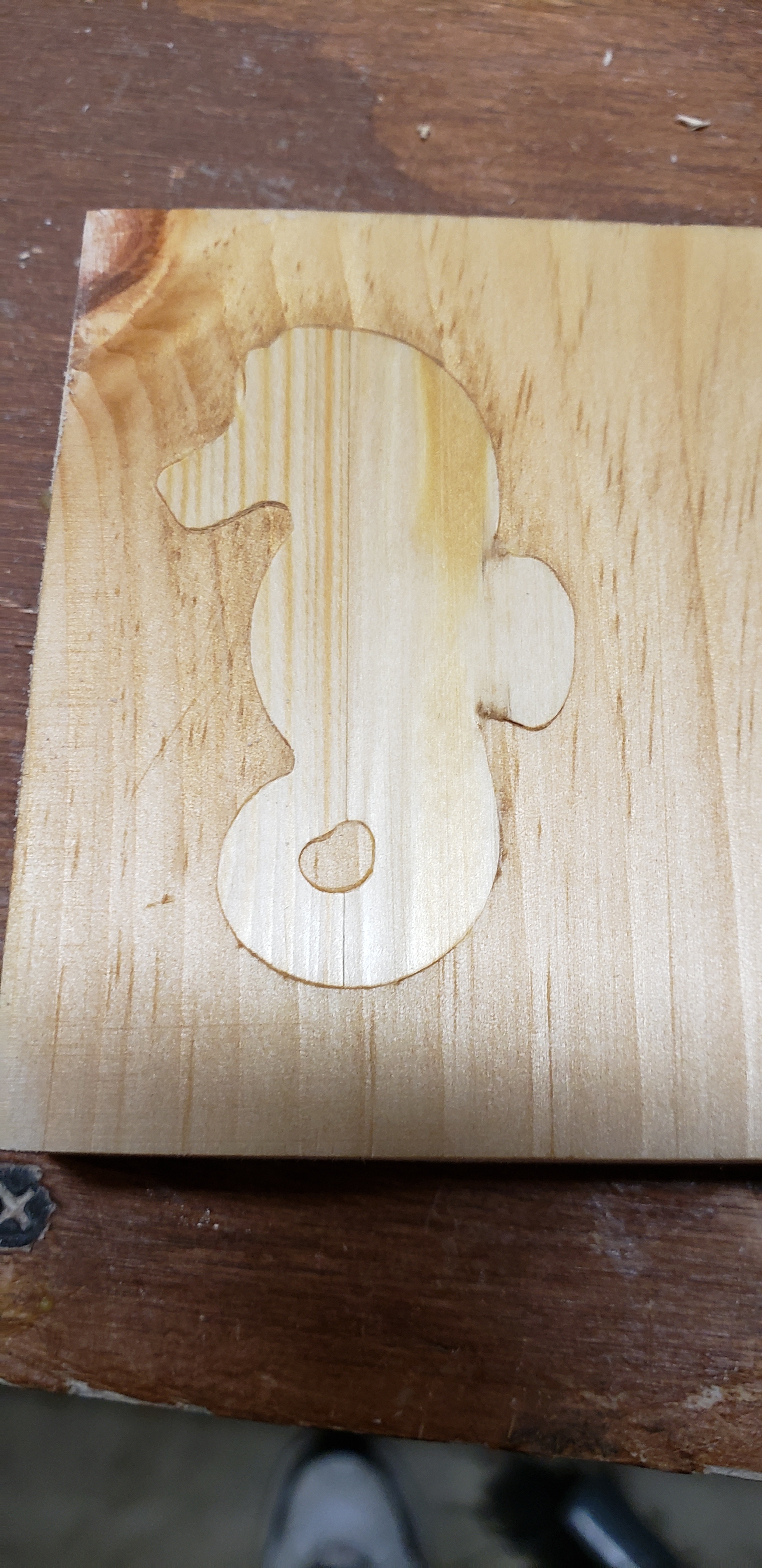
The inlay in the picture was done with two different tool paths. The first one (female) was cut from an outline of the shape I wanted. The second one (male) was cut from a copy of the outline however, it was flipped over to reverse the outline.
The trick is in the cutting depths. - I used a 60 degree engraving bit, I cut the female to a depth of -3 mm from the stock top.
I cut the male with a stock top offset of -3mm then cut it to a depth of -6mm from the stock top.
This gave an inlay (male) that fit in the female without much manual clean up.
The problem I had with this technique is for some reason, the engrave path is not faithful for the female part. If you look where the seahorse’s fin is, the female did not cut the angle on one side. I worked with Fusion 360 to try to correct this but couldn’t find a solution that would follow the outline correctly.
I thought I would try a different cutting strategy, I used a 2D contour and offset the male part to fit the female. - I can confirm that this is NOT the way to go. There is just too much work to clean up the parts. I haven’t finished the glue up yet but when I do, I will post a picture of the inlay, I don’t think it’s even close to the first one.
My plan now is to try and establish why the engrave tool path is not faithfully following the outline that I have. I will try a different outline to see if that helps. I created that outline from a picture on the Net so I am not sure if there is something wrong in that creation. I may try creating an outline from scratch.
I will update here once I have some news.
It required far too much post machining finishing.
I am going to try to get the Fusion 360 engrave strategy to work. If that doesn’t work I may try it in a different CAM software.
You can definitely see where it clips the angle. If I mess with the start point I can get it to clip the other angle and follow the original. I will post some screen shots
That’s super weird. I use it a lot and the only issues I’ve had were not setting the depth correctly and chucking in a bit with a different angle than I used in the cam.


