I’ve just started using ESTLCAM again after Fusion 360 broke the PP last weekend. I make a lot of guitars and use two holes on the center line of my designs to screw to my spoil board and then use one as my zero point because I have to flip the pieces multiple times. This way I don’t have to be concerned about being perfect with my workpiece dimensions. I can’t find a way to change the zero point of the STL or mask in V12 like there was in V11. Am I missing something simple, or is it no longer possible?
Have you seen the new PP?
I did thanks. But now I’m relearning ESTLCAM again as a backup for the next time Fusion360 has an update and crashes the PP. Always good to have contingency plans ![]()
So in ESTLcam version 12 there is no longer an “Origin” button?
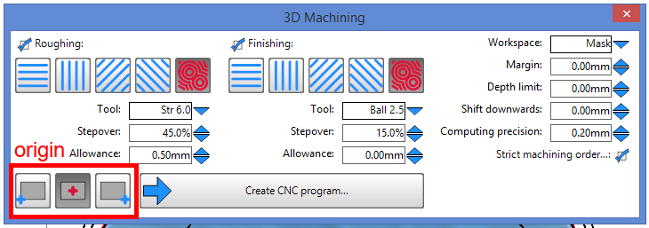
The v12 STL origin can be center or left/right front (bottom left icons). While it would be nice to be able to enter X,Y coordinates to offset the origin relative to the center of the STL, center is safest/easiest when machining two sides.
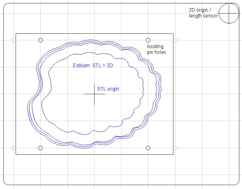
I use the v12 3D > 2D to save a mask file and a locating pin, perimeter cutout, etc. file. I center the mask on a CAD gridpoint (same spacing as my Estlcam and spoil/vac board grids) and add my locating pin holes, 2D origin, etc.
When the STL is ready to machine I send the machine a goto X,Y command (e.g. X-5 Y-3) to get to the G-code center origin and zero X,Y. For tool changes I give an opposite X,Y command (e.g. X5 Y3) to get to my tool length sensor/2D origin. With a vacuum fixture that can accommodate various projects I use a custom PP file that has tool change and program end G00 lines added to Texts.
…It occurs to me that using homing, a single (relative to machine zero) center origin (for 2 and 3D) and a fixed location for the length sensor would be more normal/straight forward than my align/mount everything relative to/on grid points.
1 Like
It looks like I can add another v11 feature that is missing from v12. In v11 there are two Set workpiece zero options for STL’s. The Vertical edges option can set the STL origin to the center or any corner of the STL. The Show complete wireframe option expands the options to any wireframe intersection or circle center.
I’m not clear on how a v11 locating/mounting hole origin helps. A point of my earlier post was that an off the material tool change (and program end) puts the spindle out of the way when flipping the material is required. A related missing v12 feature is being able to insert an off the material pause (v11 Drill > ‘insert custom g-code here’) when no tool change is needed.
That’s the 2(.5)D tools for SVG and DXF files, none of those tools are available when you open a 3D STL file
.
Dave,
I had the same issue. I know it is not a one click solution, but I used the Creat macro button option in the machine setup menu to create a go to x value y value command with my different jigs starting coordinates. Then right click the x and y values, displayed in the top right corner to reset them to zero. I believe you can also left click to type in a value, so I believe you can home it and have the correction xy in; Your origin - the xy moves from homing 0 to your intended origin. Once you calculate the home - origin value, you could engrave it on each jig for quick reference.
1 Like