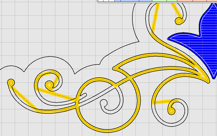
Has anyone ever had a tool path “shortcut” to another section like this? I think I’ll switch this to a central line and engrave instead of cutting as a “hole”. This art was optimized for the 1/4" endmill but I wonder if at certain radius it won’t work so the tool just goes to the next spot where it’ll truly fit.
Try a smaller tool diameter to see if that fixes it
1 Like
Might try using the finishing pass without a tool definition to slightly increase the cut, which might allow the tool to follow the pattern. I can’t remember if you need to make it negative or positive - but one makes the toolpath slightly wider. (like 0.2 mm)
1 Like
Smaller tool did/does fix it yes so it must be a matter of the larger tool just not fitting on some of the curves. I’ll try making the artwork a path to engrave instead of a hole. I’ve just never seen the tool path just jump right across the non work area like that. Usually if a hole can’t be completely cut it just cuts what it can and then leaves the rest uncut.
3 Likes
I think the geometry problem of trying to know if the bit fits, along with knowing how to skip along an arbitrary shape to the next part where it does fit is a difficult one. Estlcam probably doesn’t work in this corner case. At least it actually did make the result obvious. I’m sure there are more subtle times when the user doesn’t notice it.
I ran back through a pile of CAM files today and converted many of them to single stroke paths rather than closed shapes to be treated as Parts/Holes. It made setting up the tool paths way easier, that’s for certain. Just requires understanding how the cuts will be made so I can do what I need on the machine before removing the ice to finish off with the chainsaw/die grinders/hand tools.
I’m amassing a library of precammed carvings as well as precammed elements that I can mix and match to create all kinds of sculptures on-the-fly by letting a customer choose “Top A”, “Middle section C” and “Base E”. Tomorrow I’ll see if my plan will actually work by copying and pasting elements together in Estlcam and running some test files to make sure the machining orders don’t conflict or create unnecessary wasteful moves. I figure if I stick to machine order numbers from 1-200 for the tops, 200-400 for the middles and 400-600 for the bases I should be able to predetermine the router flow.
I even set up a dual funnel luge carving today following the engraving single stroke plan. The LR will mark all cuts to be made by hand and precisely locates the two exit points for the alcohol tubes. I’ll leave it to your imagination the final sculptural form of that luge but I can assure you, that type of luge is a very regularly ordered one. Best part - the cut time is only like 11 minutes in the machine and what I take out of the machine probably only needs 20 minutes of hands-on time. Which is great - because this carving will have plenty of “hands on” it when it arrives at the parties.
I’ve said too much. ![]()
3 Likes
With straight tool Holes the primary tool always needs to fit between all the drawing lines. If there is any question (not in this case) zoom in to the tight spots to make sure the path is 100% inside the lines.
I don’t understand how engraving lines can reproduce that drawing or how that is somehow easier than using a smaller tool or using the Resize tool to scale the drawing up a tad (100+%). Carving that drawing with a V-bit is another option.
That is exactly what Estlcam does when you add a Pre-pocketing secondary tool path, the pre-pocketing tool will cut whatever it can and leave the rest for the primary tool to cut.
While Kelly’s drawing isn’t a great example, if you zoom in you will see that the second curlicue knob? needs pre-pocketing. If Estlcam is consistent (haven’t tried it) the pre-pocketing tool can be the same as the primary tool (no tool change required).
1 Like
When I set up the original artwork I found a stroke width (in Illustrator) that ‘fit’ the 1/4" endmill. Once the drawing was complete I converted the stroke to an outlined shape and merged intersecting shapes into one. My guesstimation of the stroke width that would work with a 1/4" endmill was a pretty good plan except when curves get added to the equation. I guess the open shape pinched in too much such that the 1/4" mill wouldn’t fit anymore. By using the original path instead I can choose any bit to run along that path as the path is determined by the centre point of the cutter, not the space the cutter must fit into. Technically I could load any bit shape or size I wanted to and the same gcode file would run no problem.
The other question still remains though - why did the path just jump straight through the non cut material to the next place the cutter ‘fit’?
My bad, I assumed the line spacing was variable width.
Interesting. Thanks for directing me to that.