My LR2 is almost complete and I’ve noticed that one end of the gantry is twisting as it raises off the blocks. I re-read the instructions and it stresses not to overtighten the screws in the printed XZ part. I loosened every screw on both sides of the gantry to the point where the z-tubes were slipping out and it did not seem to affect the twist. My current suspect is the y-plate, so I plan to take the bearing assemblies off of the plate to make sure the mounting holes are level vertically. It looks good visually, but that’s all I can think of that would introduce torque along the x-axis. Has anyone seen this or have other ideas?
Attempted gif video:
Not sure the cause but it could be that it’s not actually twisting when it raises but actually twists when it lowers and when it comes up it goes back to its relaxed state. Adjusting the top or bottom screws can result in minor adjustments but not anything that dramatic. If you have some parallel blocks of would or a level I would suggest putting that on your table, then letting your x axis tubes sit on the level surface and you under your four screws on your z tubes and then re tighten them and make sure both x bars are still sitting on the level/parallel block when youre done
Thanks for the ideas. When raised the left side is significantly different level than the right. To make the bubble level I had to raise the end by about 3/8". Based on this it does appear to be twisting once off the YZ rests.


I attempted your suggestion to level it. I raised up the Z axis and rested it on a couple of small paint cans then unplugged the power and pushed it down to ensure it was even. I loosened every bolt and screw on both Y-plates then re-tightened them when I was sure it was level. Unfortunately this didn’t help. I think next I’m going to elongate the holes on the Y-plate to allow the side to slide in if it needs. If that gets rid of the torque I’ll re-tighten then use the CNC to cut new Y-Plates.
Thank you for the help. I think I’ll get it fixed, but I’m not there yet.
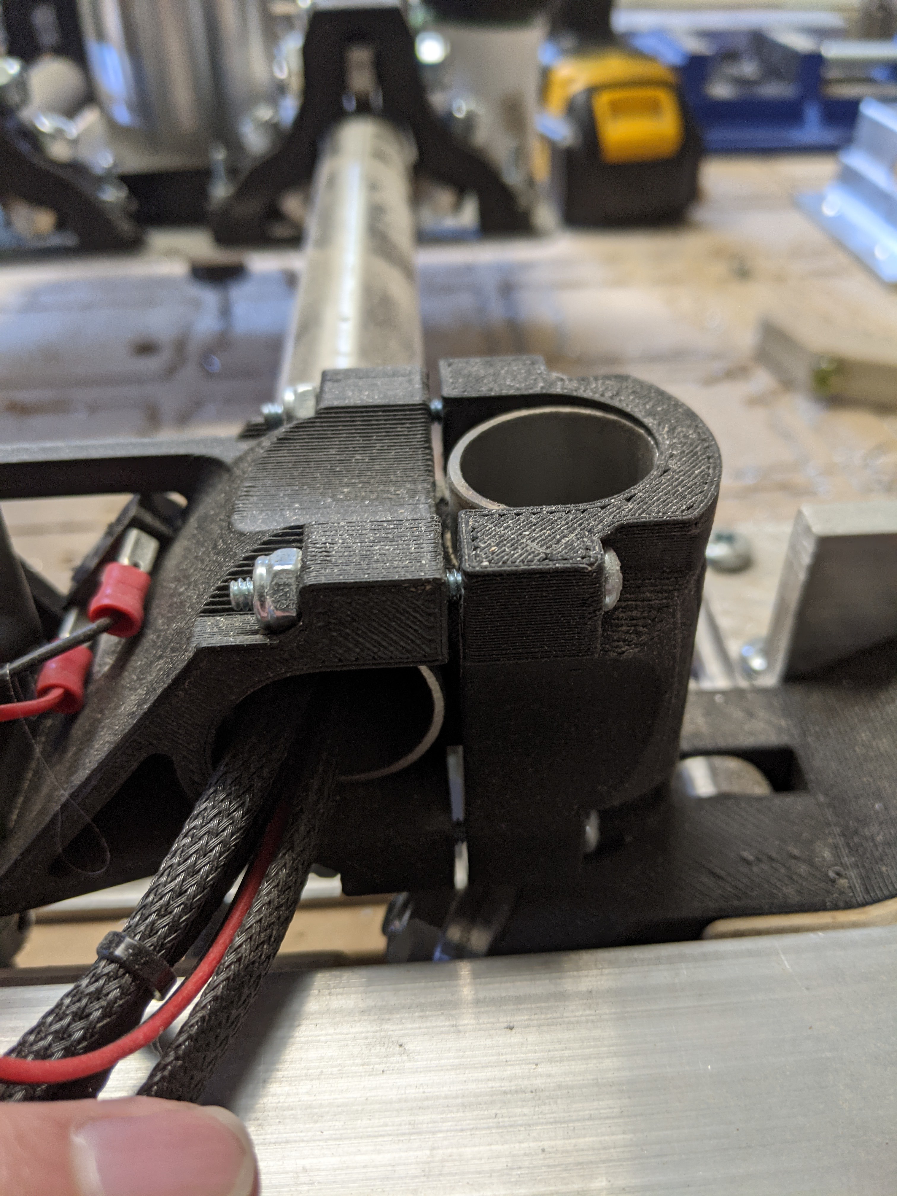
It looks like your parts are all bottomed out here. They’re should be a small gap which might be why loosening or tightening your screws didn’t help. Are they touching at the top and the bottom?
This is how mine sit as printed from Ryan
They are. I remember reading the instructions saying make a similar gap in all, but my z-tubes will fall out if I don’t snug them down all the way.
Edit: I verified that I downloaded the appropriate 25.4 vs 25mm files. Might still be a printer scaling issue though.
Are you using 1" tubes and then 25.4mm prints?
Yes. I edited my last reply as you were typing. My tubes measure 25.4 and those are the files I printed.
1 Like
You have the tube saddles installed? The ones that go between the x pipes and the z pipes?
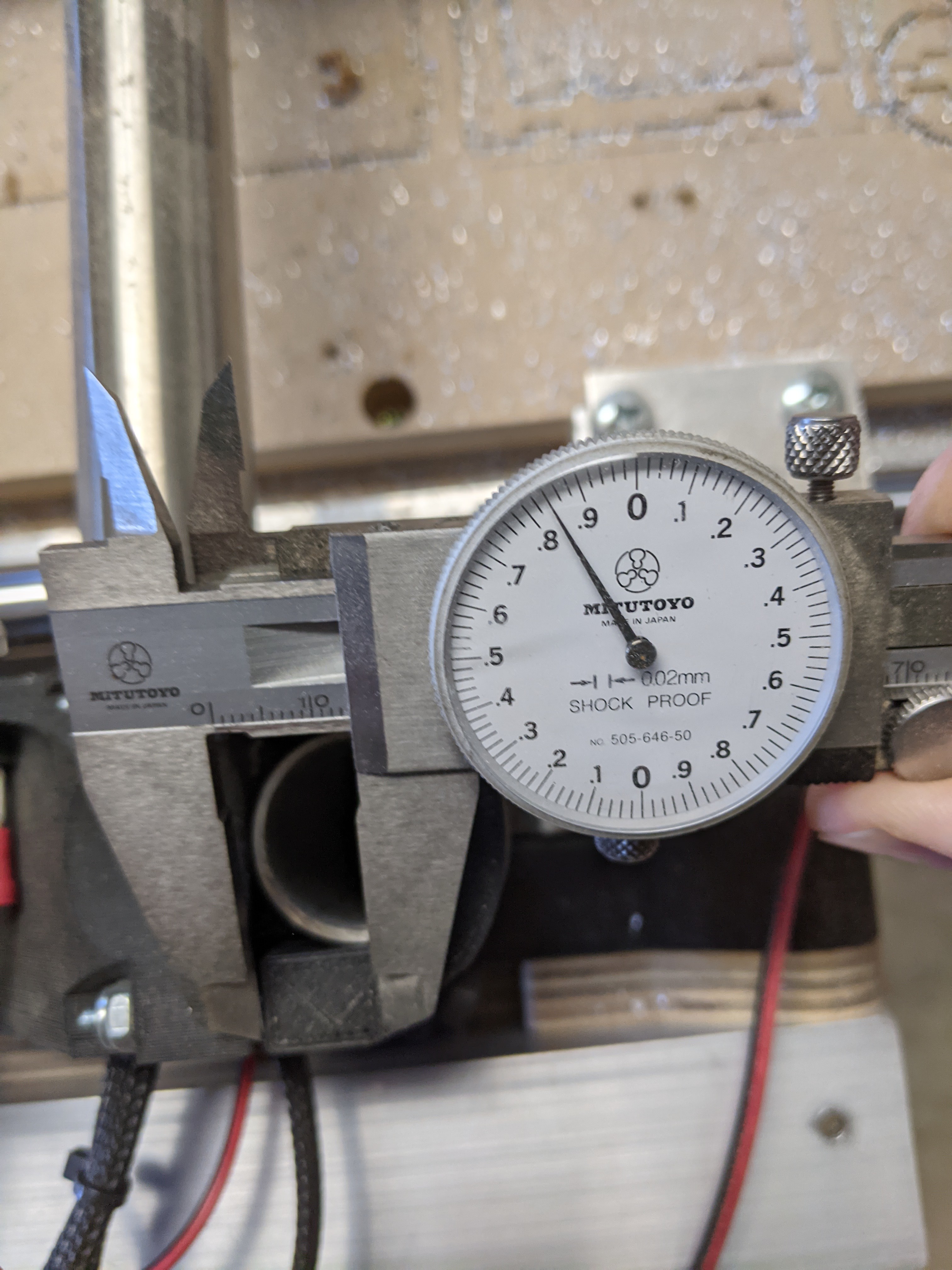
Saddles are in there. Harbor Freight thinks my tubes are 25.4 and the interior of the printed piece is 25.5. Is that close to what yours measures?

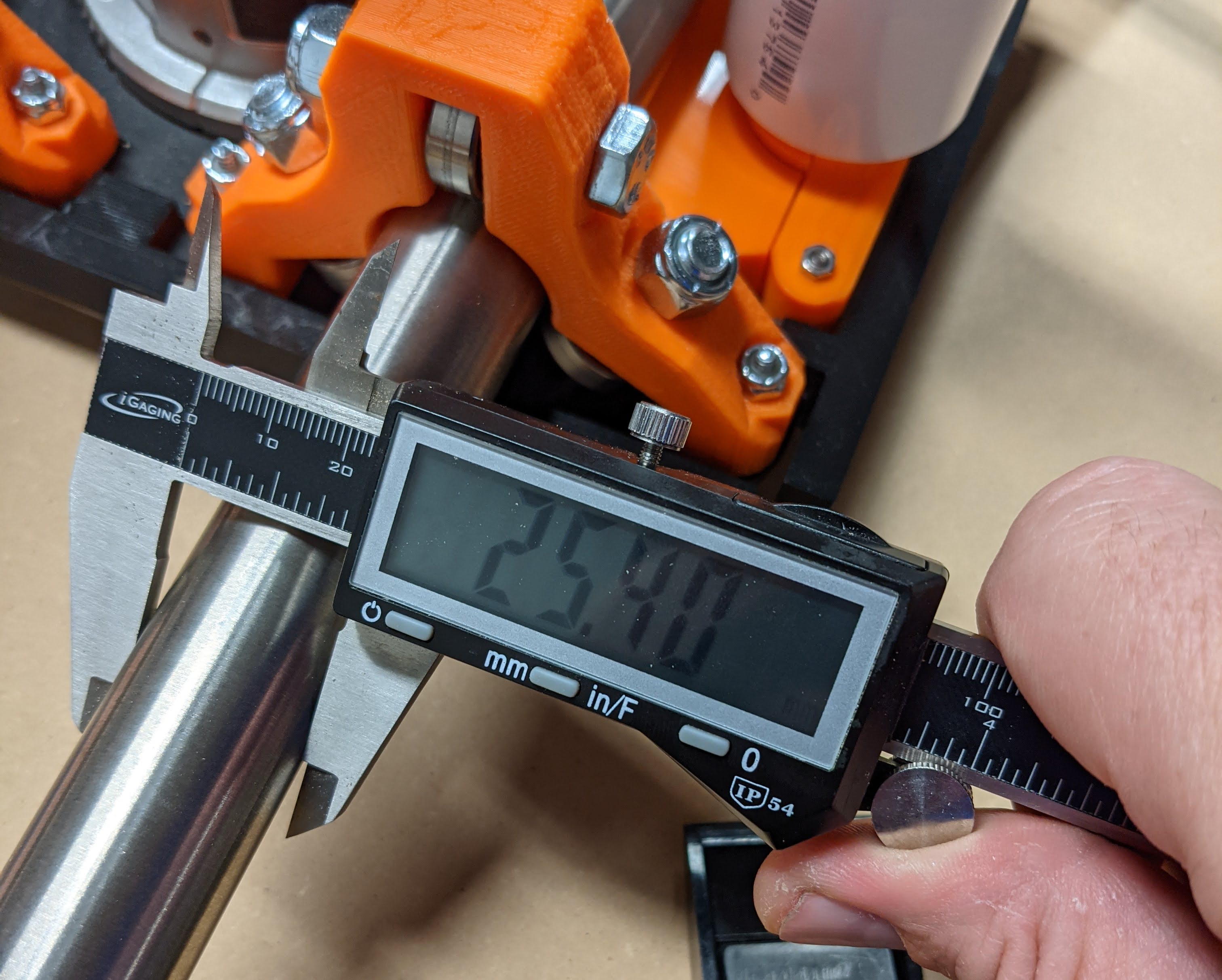
Yup, those measurements seem to be the same and this little stand off that the fastener goes through is 13.84mm
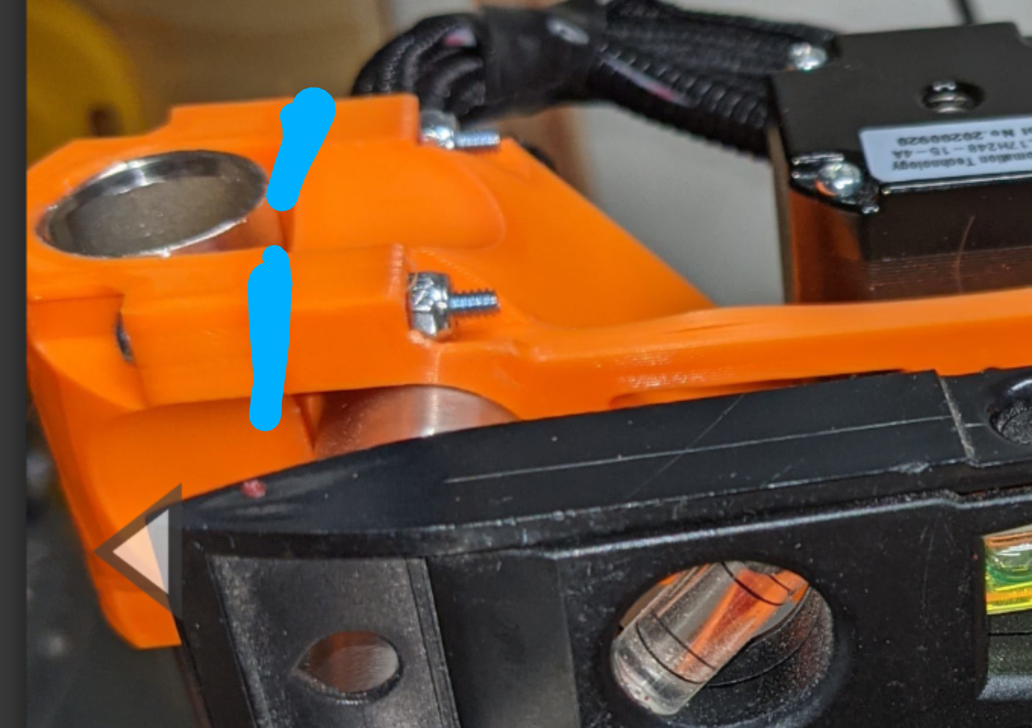
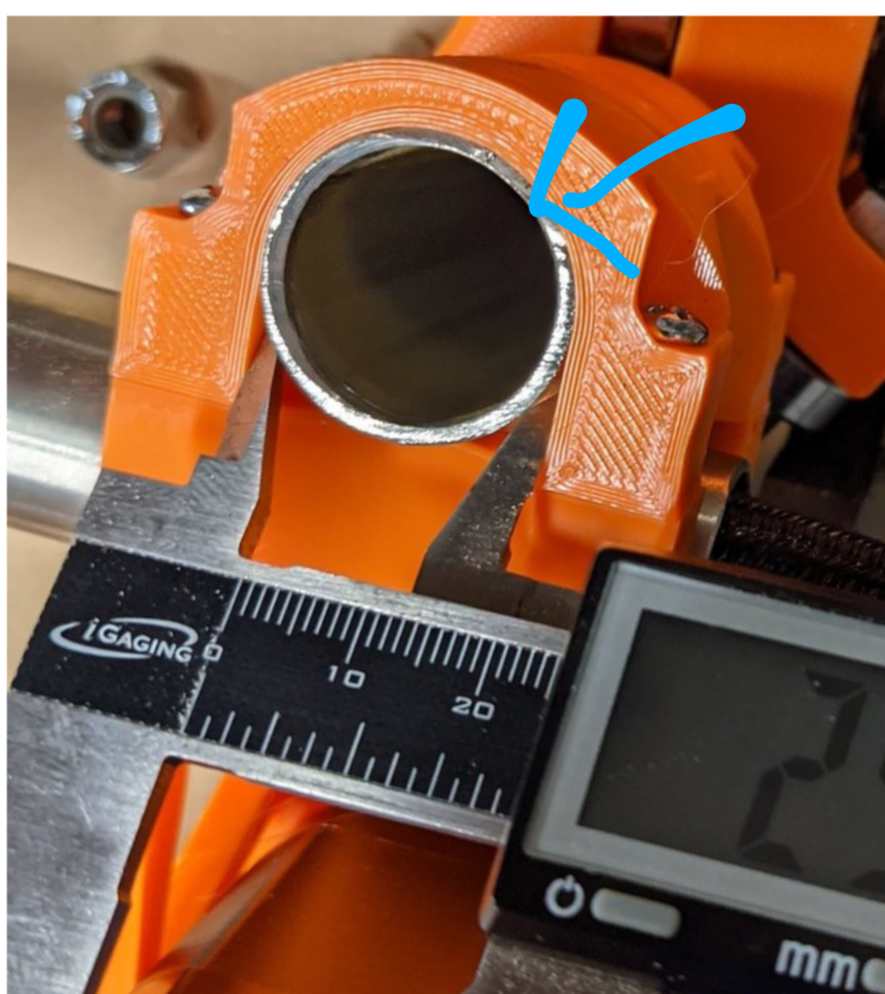
Hard to tell in the photo but is there a small lip over the end of the pipe here that would prevent it from sliding all the way up?
1 Like
There should be a piece between the X and Z tubes, I can’t see it in there…

Piece 6 “J Spacer”
Without that, the spacing for your Z axis rods will be wrong.
1 Like
Yeah. That’s what I was referencing as the “saddle” above. It’s installed, but I just reprinted a couple since that does seem like a good suspect. I’ll swap those out tomorrow.
Thanks for the suggestion.
1 Like
The pipe butts into that lip. Is it supposed to pass all the way through? I thought that was there to reference the end of the pipe position.
1 Like
That’s correct, just wanted to make sure you didn’t have them upside down. I’m running out of ideas but those two parts touching each when there is supposed to be a gap seems to be suspect #1
2 Likes
I would check your printer calibration. It has to be something large though, a 10-20mm cube is not accurate enough.
This is a quick test, 100mm Calibration Axes by salfter - Thingiverse
Or the other way, Printer tests and calibration
Thanks for the idea. Scaling makes sense, but I just loaded XZ_Main.stl into Cura and it said it was 151.4mm wide. I measured the part with my calipers and it was 152mm. That seems to be within the tolerance of my cheap Harbor Freight calipers.
I’ve re-printed 2 x J_Spacer parts, because it’s easy and low-hanging fruit. I’ll compare the new ones with the old to see if there’s any difference.
Something about this photo was bugging me, so I just looked at my own parts to confirm.
my end caps, as printed by Ryan have the top surface as the one that was originaly to the bed surface. These parts look very much like that is the top printed layer. It still has the ridges from the extruder nozzle moving over it instead of the “squished flat” look that the bottom layer usually has.
I rather suspect that this piece as shown in the photo was installed upside down.
However this should not allow the parts to be jammed together like you show either, since now the lip that should be over the edge of the steel pipe is down at the bottom, and should actually be increasing the gap.
This will also most definitely not allow the Z tubes to remain square, as it will try to force the bottom of the tube inwards.
The other piece opposite this has the bit that is meant to hold the X belt, and it should be good. but still should not be jammed in right next to the XZ piece. I expect that would also cause a slight misalignment with the X belt by a couple of mm.
Bingo!

I had it upside down and the ridge was squeezing the pipe in at the bottom. The ridge got a bit crushed, but when I reversed the piece the tilt virtually disappeared. I’ll reprint that part this weekend. I’m still not sure why there’s no gap, but as long as it works I’m fine with that.
Thanks everyone for the help and the attention to detail. Who knows how long I would’ve chased ghosts. Both RobP and Supraguy had the right answer, but it only lets me mark one as the “Solution”. Thank you both.
4 Likes
Glad we could get it fixed and up and running again. Even if I don’t get the solution point 
1 Like