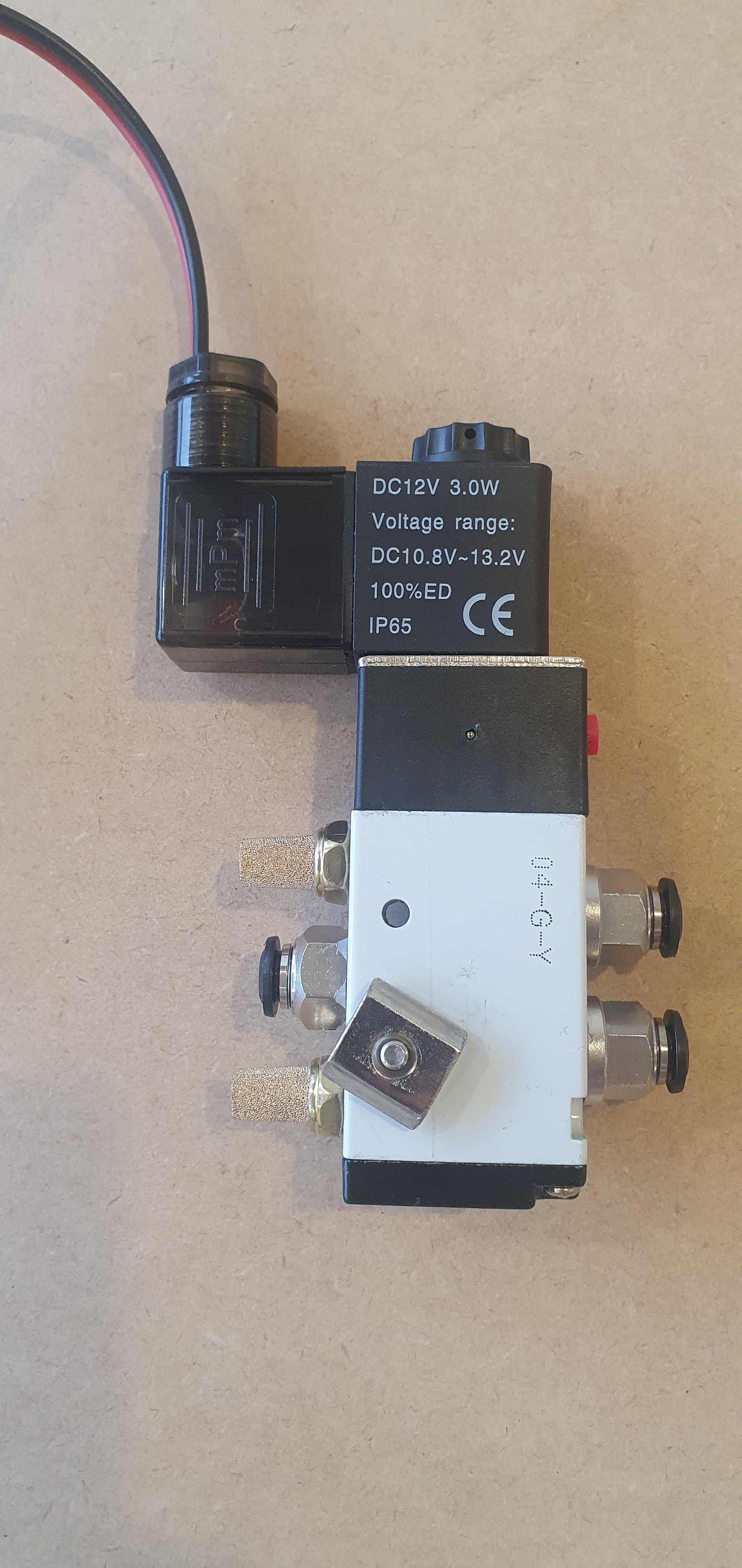
Ok - I’ve got my LR3 powered up and making movements! I’d like to use the onboard flood / mist MOSFETs to turn on / off a pneumatic solenoid of this type:
My question was really about using a solenoid on the mosfet. My understanding is that your trim router has a flyback diode built into it which stops a voltage spoke when it’s turned off…the solenoids don’t have this.
Most relays say they have protection for these voltage spikes but my experience with the little Arduino style is mixed.
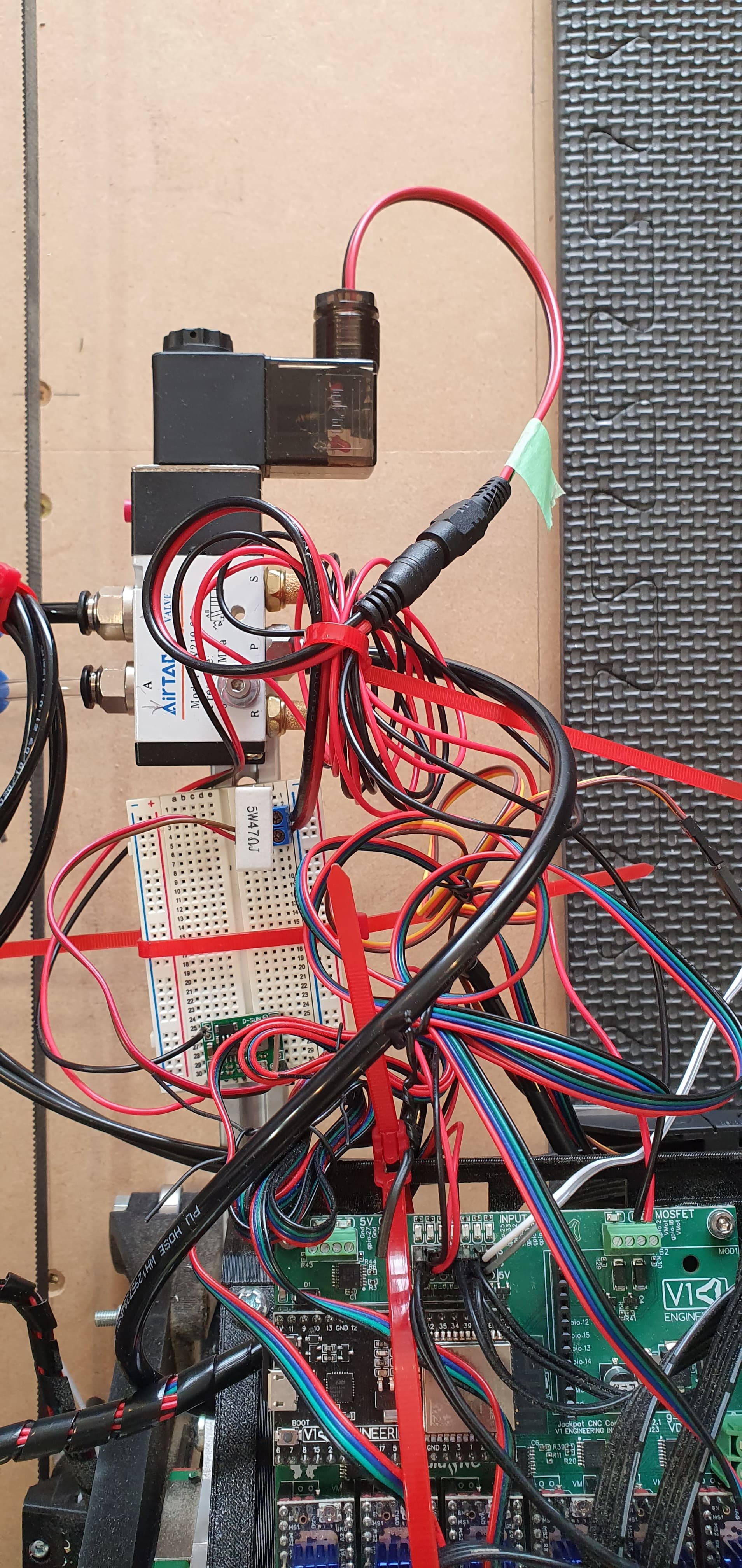
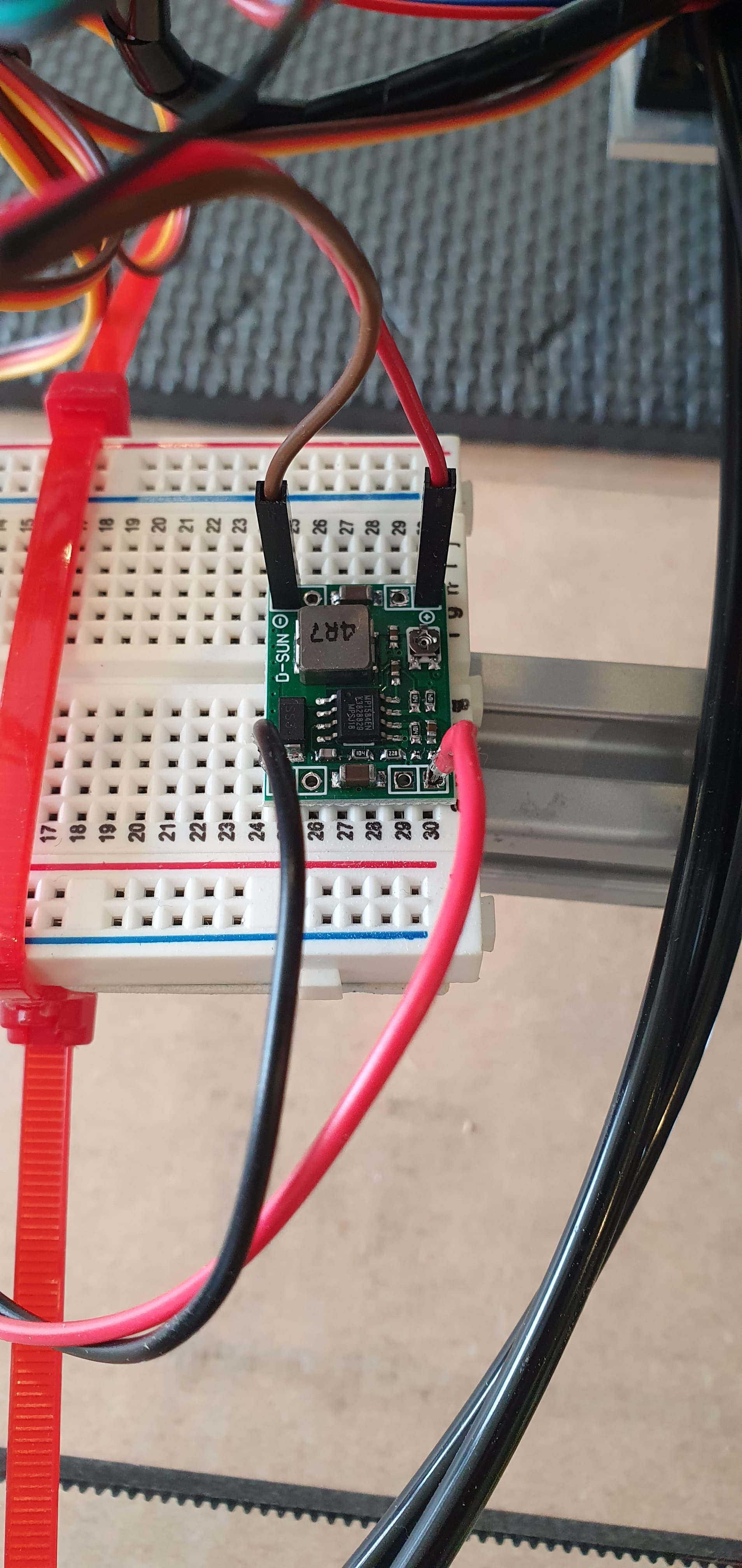
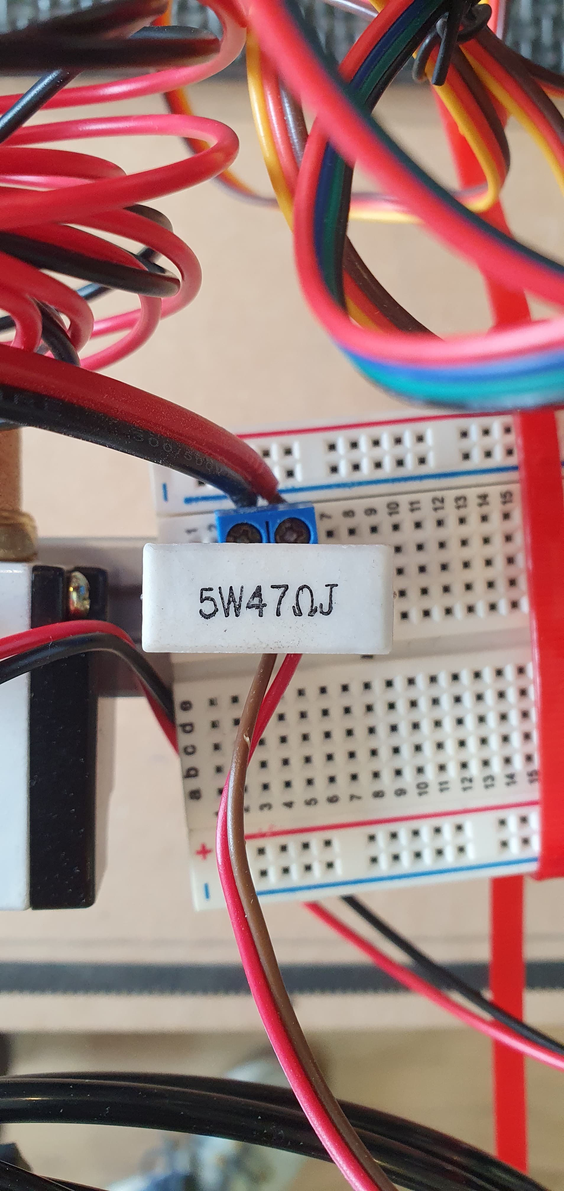
I’ve got a 24v > 12v stepdown board attached to the 12v solenoid bridged with a capacitor to smooth the voltage and it seems to be working well.
Some comments and questions. Meant to be constructive.
It seems to me to be very rube goldberg to have all that work to try and make 12v for a solenoid when you can get a 24v solenoid. Just buy a 24v solenoid.
That’s not a capacitor. That’s a 47 Ohm power resistor rated for 5W of dissipation. If you have it hooked up across 24V, then I bet it gets pretty hot. It would be dissipating 12W of power. It’ll eventually burn up. If it’s across 12V then it’ll dissipate 3W of power, but again you don’t want a resistor as a protective measure.
In any event, you don’t want a capacitor anyway.
If anything, you want a flyback diode at the jackpot.
It’s also a bit sketchy to use a DCDC converter that way, it will have turn on transients and may have other issues, and you’d still need a flyback diode at its’ output.
My advice is to buy the 24V solenoid, run the jackpot off of 24V VMOT power, install a flyback diode at the jackpot.
If your run of cable to the solenoid is long- over a meter or so, you might want a flyback diode at the solenoid and at the jackpot.
I have a slightly different solution than Jim there, but agree about that resistor. That is asking for trouble.
My approach is this: put the 12V adapter at the power supply to provide 12V constant. Test continuity to ground from the 12V to the 24V ground. If it has 0 ohm continuity, (or at least very low resistance) ignore the 12V ground entirely. You don’t need it.
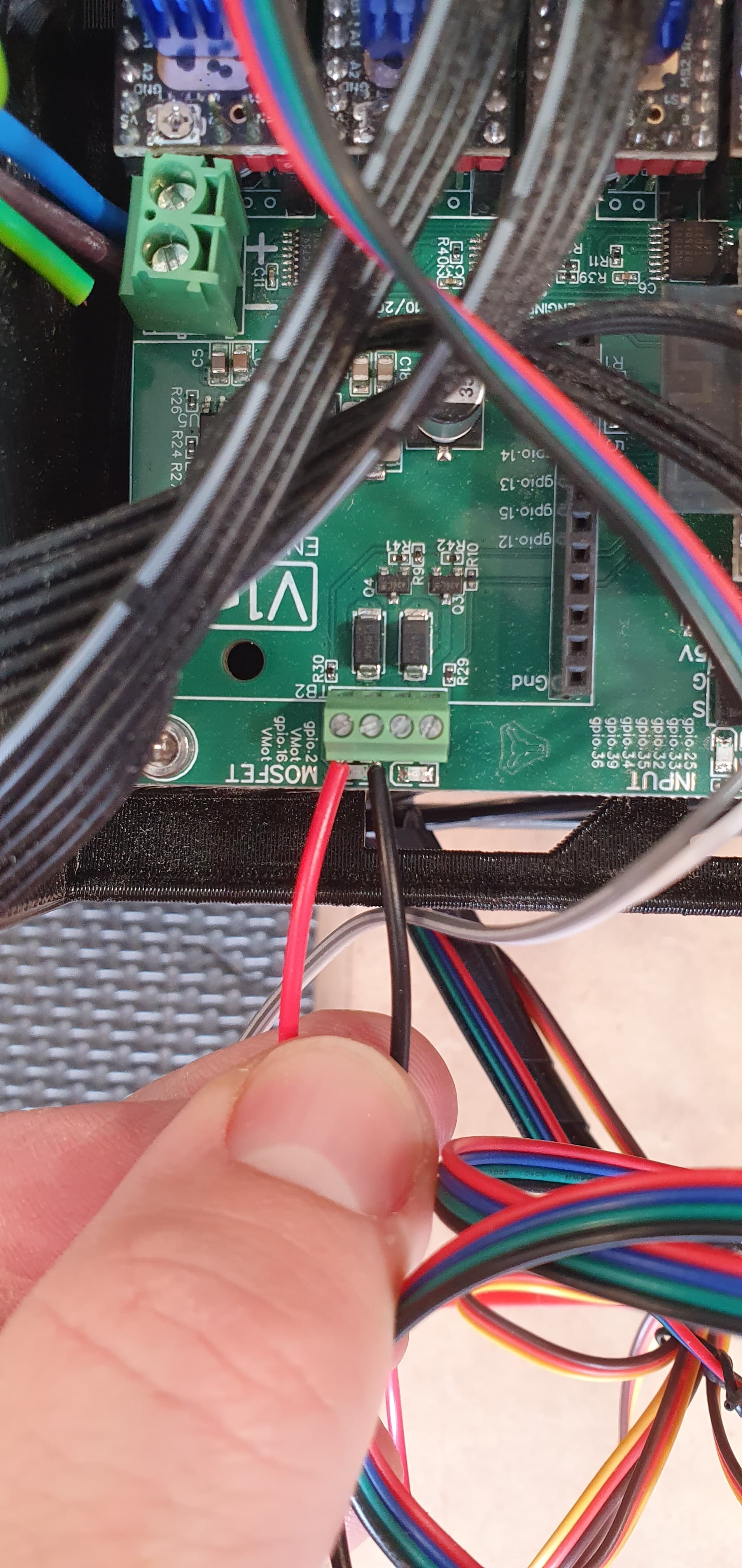
Supply the positive lead on your solenoid, or any 12V fans you may wish to use from the 12V supply, and connect the ground leads to the MOSFET outputs.
The MOSFETs switch the ground side on and off, and don’t care if you use the 24V, 5V, 3.3V or your new 12V power rails. Your 12V buck-boost can also deal with some transient spikes from switching noise. Most circuits utilize a zener diode as a part of the regulator design. It’s usually enough, but if the solenoid is the only think on the 12V circuit, it should be fine anyway.
I use a circuit like this to use 12V LEDs on my 24V printer. The +12V is supplied from a buck-boost, and thr ground side switching is done on a nominal 24V MOSFET that thinks it’s controlling a fan when the bed temperature reaches 30°C this lets me light up the print bed while the printer is working, but the lights are off when it isn’t. It also lets me know if I forgot to turn the heater off, lol.