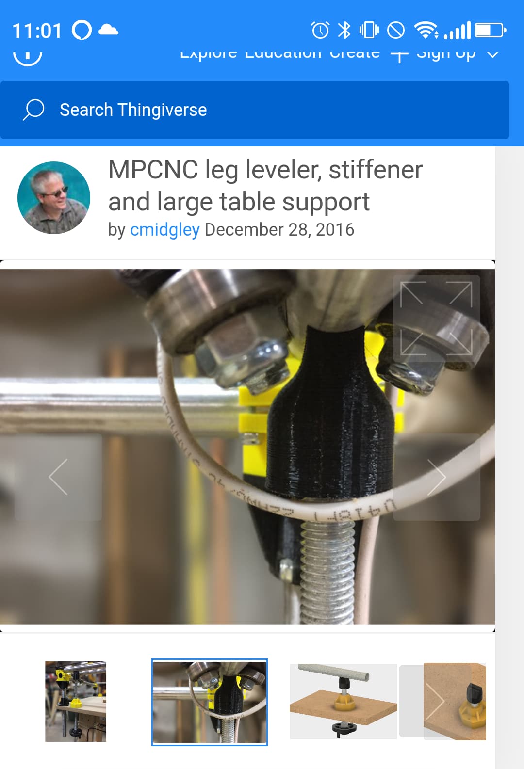
I have been looking for an easier way to adjust the level of my corners & came across this idea: https://www.thingiverse.com/thing:953976 The problem was I wanted to use my same corner styles, so I set out to remix this in openscad. My biggest hurdle was getting the threading the way I wanted & found an openscad screw threads library that worked well for me at http://dkprojects.net/openscad-threads/ . I used a thread angle of 40 degrees since that printed a lot better than the default 30 degrees. With a Pitch of 4, turning the nut 1 revolution will raise or lower it 8mm (4mm below the nut & 4mm above). I was originally going to make this design the same way the original designer did, but then realized a turnbuckle would be fun. I had enough room inside the turnbuckle to add a 1/2" EMT which should make it quite strong. I need to make a couple more small tweaks to the design, but I am pretty happy with how well this initial test went. I was tired of using index cards on my corners to get it level. I have an option to have the threads only at the top like the original design, just in case this does not work out. Here are some photos of what it looks like so far. There is also an image showing the variables that can be changed on the turnbuckle.


Sweet design!
So far what are your impressions? Sturdy, any play in the threads after you tighten the locks?
That’s neat. Is there a set screw in that hole, how does that work? I want to make that and then find a purpose for it.
I tested the thread clearance with a .8, .4 & then .2. The clearance that worked best for me was .4. There is almost no play in the threads & when you tighten the bracket even just a little bit there is no play. That clearance is adjustable in openscad. I also took the liberty of remixing your Lock-CornerC in openscad to add the threads with an optional Height adjustment. 27mm might be too short to use with the threads.
If you are talking about the horizontal hex hole in the middle of the nut, that is in case you want to adjust it using a 5mm allen wrench, screwdriver or whatever fits. If you add the 1/2" EMT to center, you probably can not use that. My 32mm plastic wrench adjusts it pretty good so far. I was just thinking I could probably make something like a knurled socket open at the top & bottom & leave one on each of the turnbuckle. That way I could put some index marks around the circumference to get a better idea of how much it is going up or down.
I showed this to a friend & he wanted me to print him one to use as a mini jack. I can see there are some good possibilities for using this idea for other purposes.
I guess this is more accurately called a Jackscrew instead of a turnbuckle. https://en.wikipedia.org/wiki/Jackscrew
Yesterday I remembered an M3 thumbwheel design which works pretty good on leveling my 3d printer corners, https://www.thingiverse.com/thing:844008 . I used his openscad file to create a 32mm thumbwheel & printing that now to see how well that will work. I included a screen shot of what that should look like. For the test version, I only used 4 index numbers instead of 8. I will use a black sharpie to highlight the numbers & main ticks.

I published it today on thingiverse https://www.thingiverse.com/thing:2405370
I do not have all the corners on yet, but looked good enough to go ahead & publish.
Hope this is not too far off topic, but I am always looking for something fun to make. I ended up not using the thumbwheels but designed a thumbwheel spinning top. It is not the best spinning top out there, but was a good use of my left over thumbwheels. Here is a short video showing 2 test runs.
Way more cool that a fidget spinner!
I made a more blunt version of it & spins even better now.
I had to put off finishing putting my jackscrew legs on as there was a bald faced hornets nest in the doorway to my shed. I originally thought it was a wasp nest & was going to leave it alone until Fall, but when one of them stung me twice, I decided it was time for them to go. If I had realized it was a hornets nest, I would have taken care of it earlier. It seems to smell a little like Raid in my shed now, so I need to air it out once I am sure the hornets are gone.
Do these work with primo? Look good.
This did work quite well for me, but it was for the original MPCNC version. I don’t have the primo or that MPCNC put together anymore, so I can’t say for sure. Looking at the Primo parts, that Corner Leg Lock C Primo.STL file is similar to the file Lock-CornerC_27mmHt_RightThreads_Rev4.stl I created in that repository for an earlier version of the Primo. Think it was for the Burly version. Looks like it is similar to LockM_CornerC.STL from the Burly version. I think the only assembly difference will be the Primo part has a captive nut for that part.
[Edit]
I took a look at this & have a version that should work with the latest Primo version, but is untested. There are 2 versions Primo_Lock-CornerC_Threaded_Rev6.stl and Primo_Lock-CornerC_CaptiveNut_Threaded_Rev6.stl. I matched the Primo design for nut & screw recess diameters as best I could with openscad. Should be only a little over an hour print with either version. If you are considering using this design, I would suggest printing one of these 1st to see how well it mates with the corresponding parts. Here is the link to the files again. Customizable Jack Screw to adjust height of Corners on MPCNC by GeoDave - Thingiverse
Awesome thanks I am in middle of printing parts I will report back when I get printing done👌
Nice mod! Anyone remixed top mount to enable supporting rails mid span? Fasten to rail using Remix of model part that’s normally inserted into z axis to help captive nut.
Edit: I ST*W and stumbled onto Remix of Customizable Jack Screw Top for Mid Span Support by GeoDave - Thingiverse and MPCNC leg leveler, stiffener and large table support by cmidgley - Thingiverse, these help prevent sagging. But, guessing welded/bolted solution would be needed to prevent lift and increase rigidity, for outer rails?
@geodave Any idea why the threads in rev 32 of your files dont have threads when I open in scad? do I need to add a library for the threads?(never used scad)
Edit All good I figured that out bout cant find either of these files " Primo_Lock-CornerC_Threaded_Rev6.stl and Primo_Lock-CornerC_CaptiveNut_Threaded_Rev6.stl ." they not in the primo or burly files.
Oh I am doing the f size machine(25mm rails in Australia). I am guessing I can just scale the stl?
Yes, there is a thread library you need as mentioned in the thingiverse repository. I had this link to it. OpenSCAD threads (dkprojects.net) . It was not included in my thingiverse upload since it was copyrighted. Save that file as threads.scad file to the same folder as where you put my files & you should see threads this time when you render it. Looks like the author updated it this year. Since his file has changed, I would rerun it on all the files with threads to make sure they mate. I briefly looked at rendering difference & threading seemed the same but moved up a little. I will rerun these to see how they differ.
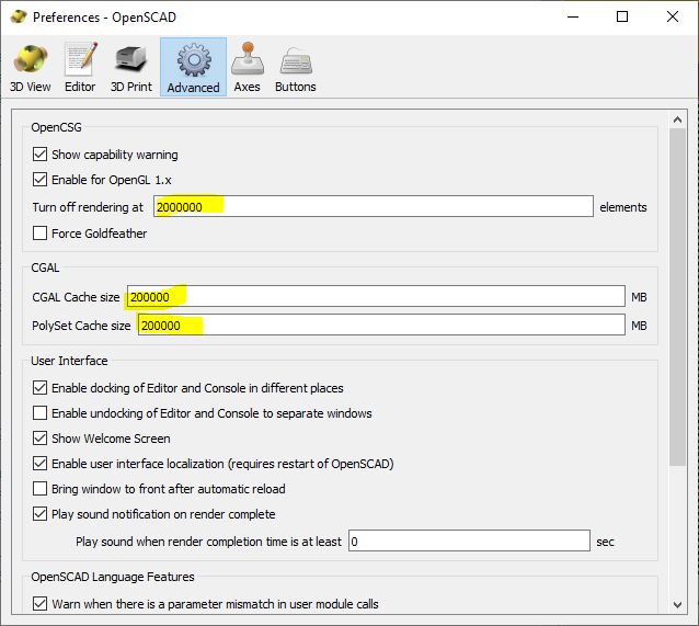
Since you are not familiar with openscad, I would suggest making these changes to the Edit/Preferences dialog. Takes me about 10 minutes to do final render (F6 shortcut key) of the Jack screw. The bottom foot takes over 8 minutes & the top one took over 4 minutes. The bottom one has a hard time with the preview, so I would only do the F6 on that one. I will have to revisit that design to see where it is bogging down, probably the hull() commands. That one could probably stand to be updated also.
Otherwise, the preview (F5 shortcut key) might not show up because of large number of facets with these threads.
I got them rendered and exported to stl’s but cant find the older primo files.
On the upper jack part it has a square/rectangle mount with 4 screw/bolt holes.
On the final primo lower corner/mirrored it has a shape on a curve not a rectangle with single bolt in middle it wont fit…
Can I just use your lower foot and add a thread to the upper lock? Of the primo part?
I did not update the lower foot since that should work as is. I will take a look at the bottom foot today to see if I can update it to the look of Primo version. Just make sure you use the left-handed threads for the bottom, since the top is right-handed. Here is a simple assembly of it.
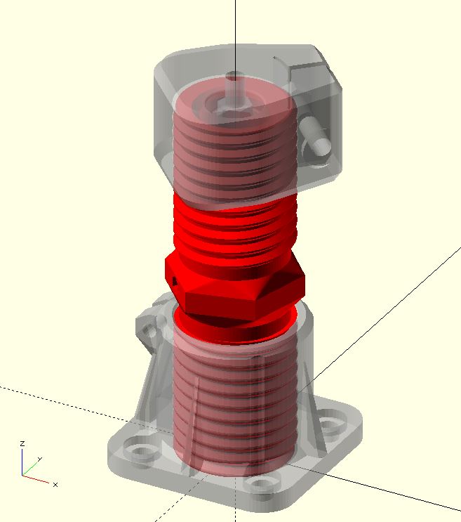
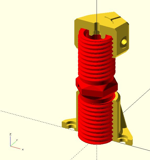
Here is the openscad code for this assembly. It is difficult to get the threading to match correctly in openscad for the mating parts. I matched it by trial & error on the section version, but not the gray top & bottom version.
translate([0,0,1])
rotate([0,0,315])
color(“red”)
import(“JackScrew_Rev30.stl”);
%import(“Flex_Foot_Bottom_M5Bolt_LeftThreads_Rev32.stl”);
translate([0,0,101+9.15])
rotate([0,0,0])
rotate([0,180,0])
%import(“Primo_Lock-CornerC_CaptiveNut_Threaded_Rev6.stl”);
Ok so I will just try add a thread to the top lock part.