I have moved forward with attempting to square my first lowrider build and upon pressing the home all buton I noticed that only the right side z motor and the left side y motor actually went through the squaring process. A little googling and digging in the forum said to use the M119 command to check the values of endstops. The results of the command are:
x_min: triggered
y_min: triggered
y2: open
z_max: open
z2_max: triggered
I assume these endstops being triggered is why these steppers arent moving during homing, because the machine thinks they are already home. So now I am trying to figure out why these endstops are always triggered.
Things I have tried so far:
Loose connections seem to be a common cause for this. I decided to focus in on the X Axis endstop since it was easiest to work with. I removed the endstop from the extension cable and plugged it directly into the skr board. This caused no change.
I had yet to remove the JST connectors from the endstop pins, so I tried that for the x endstop to see if that was causing a weak connection. This caused no change.
I put a multimeter on the 200 ohm setting and hooked it up to the X endstop. No matter what I did it always read OL. However, when I attached the multimeter to one of the working endstops, it gave me a resistence value so long as the switch was not pressed, however when I pressed the switch it indicated the circuit was broken. I am assuming this is the expected behaviour but I do not know for sure. This makes me think that maybe the endstop itself is bad, but surely I didnt get so lucky as to have several bad endstops at once.
For the endstops that are working, I notice that when the switch is pressed an LED lights up on the skr board. Other endstops just appear lit at all times.
All parts that were not printed for this build were sourced from the V1 shop. If I had accidentally chosen MPCNC firmware on the skr board instead of Lowrider firmware could that cause this issue?
Is there anything else I should be looking at here?
The endstops are wired as normally closed - or NC.
So when the endstops are NOT triggered there is contintunity between the signal nd ground pin.
When the lever is pressed they are Open circuit so therefore no continuity.
A broken wire or loose connection means there will never be continuity so the board reads open circuit or triggered. This is not a mistake it’s a safety mechanism.
Set your meter to continuity test and check each matching end of the wires and extensions. Then check across the 2 end terminals of the endstops that they have continuity when the lever is not pressed and no continuity when it is. Endstops are really simple mechanisms it’s unlikely (but not impossible) they aren’t working. Crimped terminals on the other hand are easy to break.
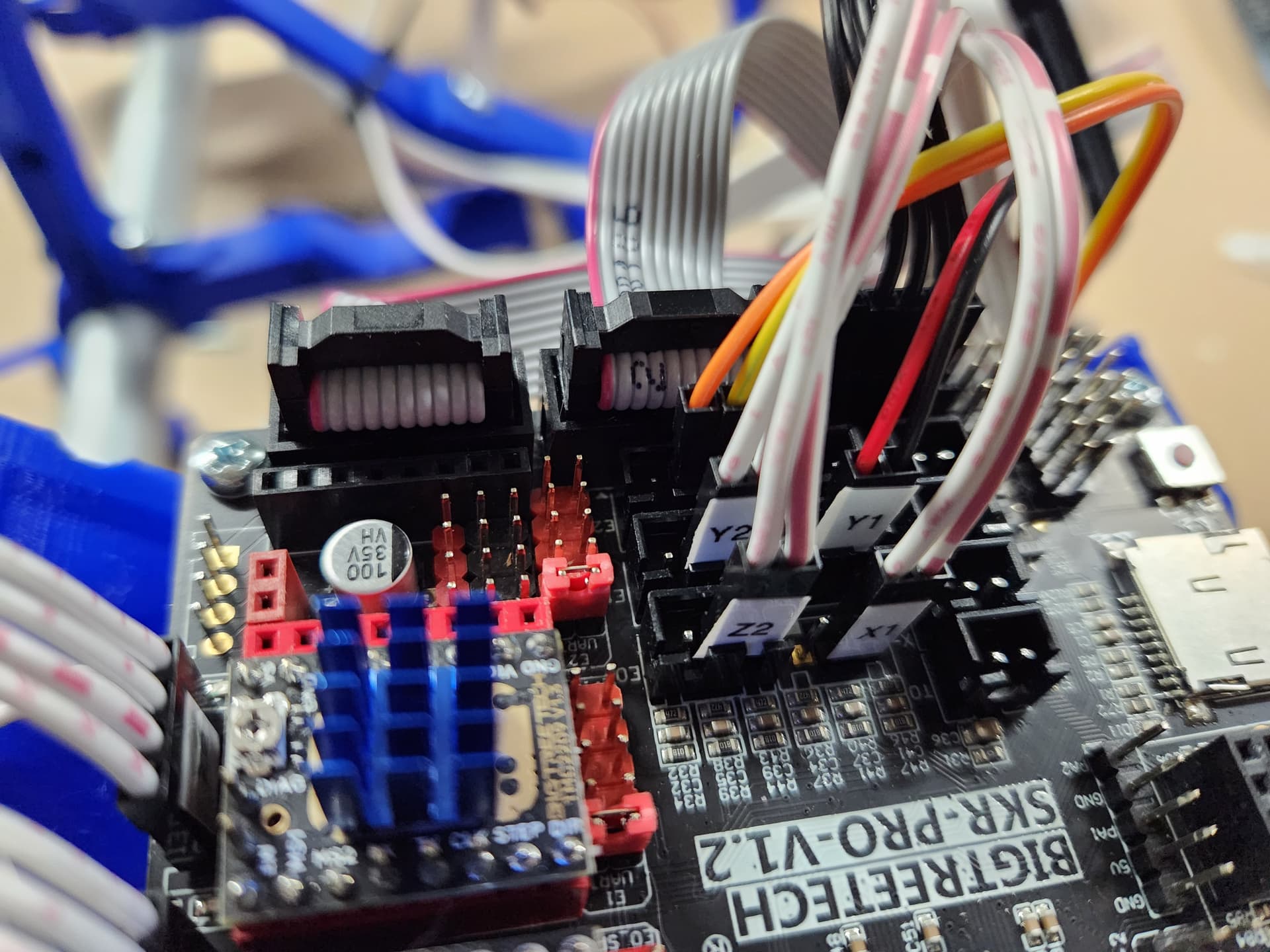
I would also double check you have the endstops on the correct 2 pins, it’s not always easy to see and the heater pins are close together.
Then check across the 2 end terminals of the endstops that they have continuity when the lever is not pressed and no continuity when it is.
My electronics knowledge is pretty basic so I was smart enough to think of grabbing a multimeter, but didnt think to check the terminals directly on the endstops! I am now able to verify that all the endstops work as expected, showing continuity until the lever is pressed.
So that would mean there is some kind of break between the endstop and the actual board. The wires connected to the extensions seem solid, and I did make sure to tape them all. This leads me to think that maybe I didnt crimp the connectors that came in the hardware kit correctly.
Is it considered bad practice for any reason to just directly solder the wires to the endstop terminals rather than using a crimped connector?
Gotcha. After going through and soldering all the connections instead of using the crimp connectors everything seems to work correctly and the machine can home itself now. Thaanks so much for pointing me in the right direction.