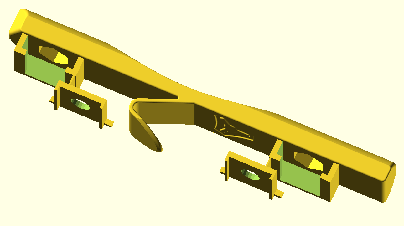
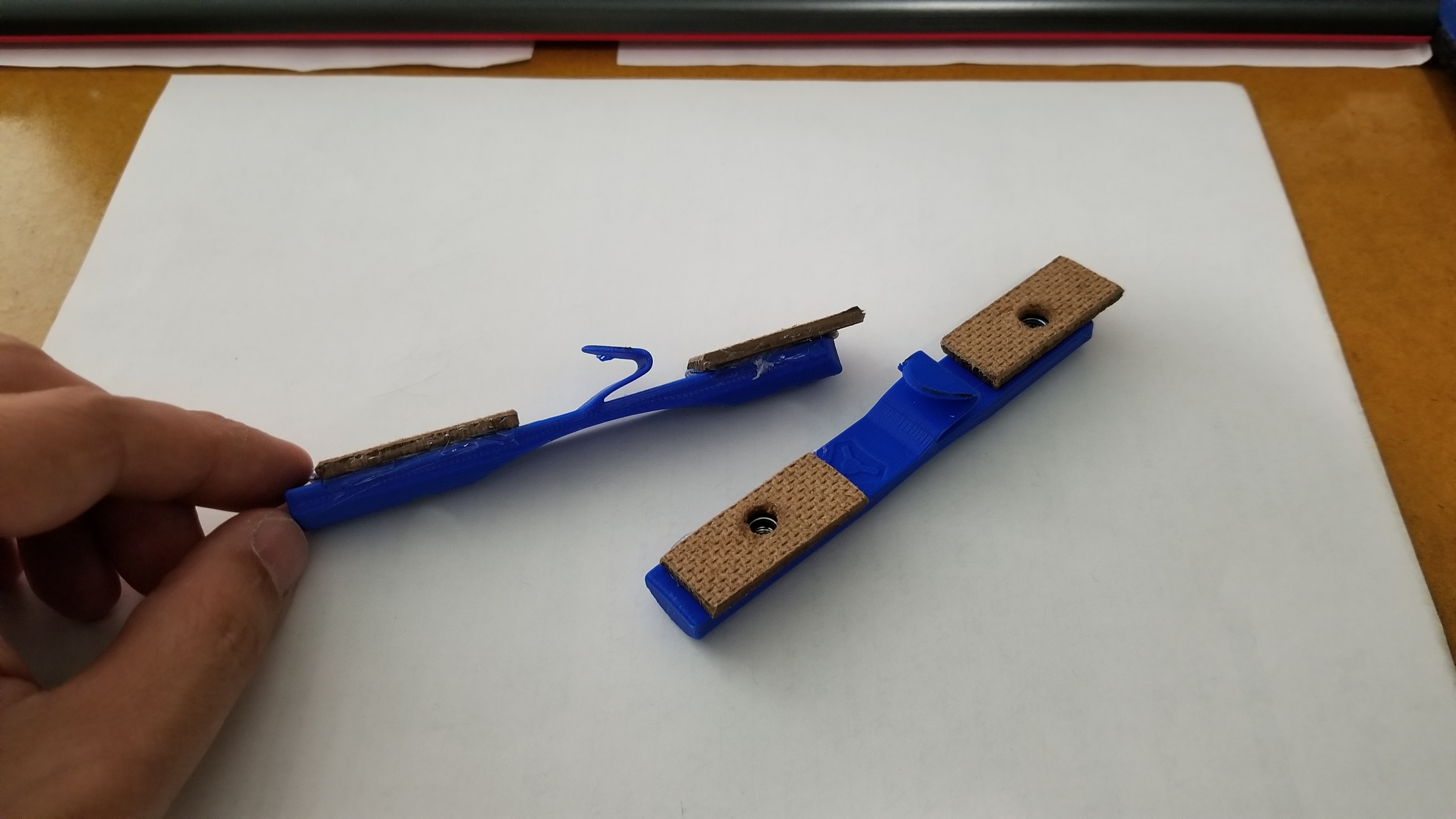
I’ve just published a modified nut trap that includes a miniature “door” that covers the spot where the nut goes. The doors are attached to the nut trap but can be easily cut off with wire cutters and then inserted (flipped). (By attaching, it prints better (probably) and it prevents tiny pieces from getting lost.)
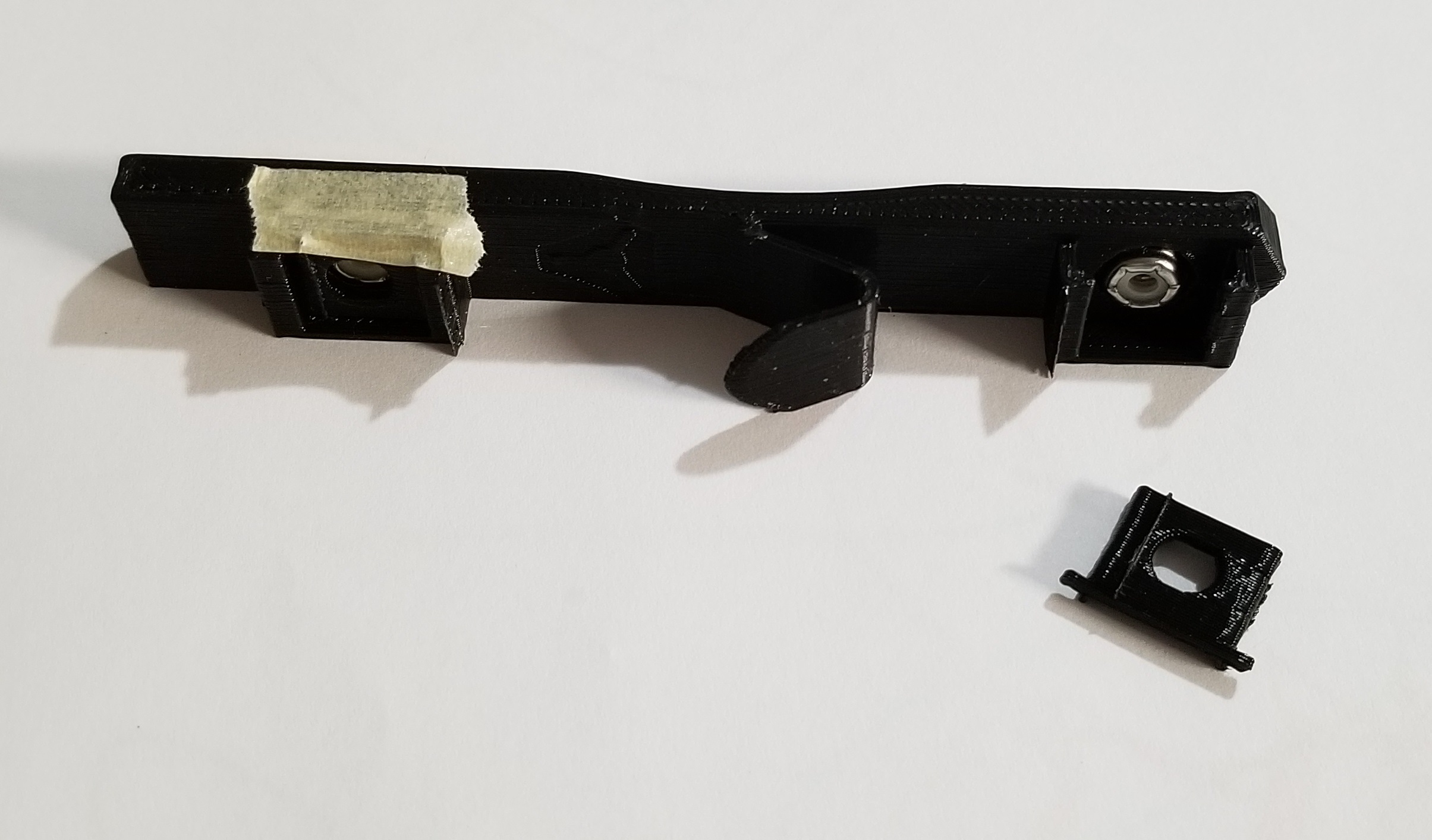
I never glued the nuts in place when I built Burly. I don’t trust myself not to get glue everywhere and ruin the nut, or to maybe glue it crooked and maybe end up with cross-threads. For Burly I just used tape to hold the nut in, which only has to work once.
For Primo, I’m more paranoid that the nut will come loose from the nut trap while inside the Z rail and I’ll be blindly trying to find a nut that isn’t there. For Burly it only has to work once but for Primo my concern is increased because swapping out tools will entail removing and reattaching to these nuts.
I probably should just glue the nuts, but why waste an opportunity to solve a “problem”?
With the differences between, nuts, 3D printers, slicing software, filament, etc…, that’s not really possible. I could design a part with a perfect press fit. You could print the exact same part and break it trying to press the nuts in. 3D printing isn’t that perfect, yet…
I see what you mean about the differences. Tweaking STLs is not for everyone.
I’ve never broken a part trying to press fit a piece though. Bad print settings? Wrong tool? Wrong technique?
The biggest problem is layer height. The size and placement of the opening of the hole (on the vertical axis) is going to be rounded to the nearest layer height. So someone that prints with 0.1, or 0.15 or 0.2, or 0.3, etc… are all going to get different sized holes at slightly different placements. There are many other smaller problems too, such as the different thermal expansion properties not only of different filament types, but even within the same material. Machine capabilities and slicer settings play a large role too.
My point being that there are so many variables to account for that its a nightmare to even get close. To paint the picture even more, I have been struggling to get exact-ish (tight) vertical opening sizes on my own print designs, not caring for anyones printer except mine, or any filament except the one I am using and I ended up having to cut the object up to where the hole openings are all horizontal, not vertical. Thats not really an option with these models.
If the printed holes are a bit too small you can insert the nuts using a soldering iron, but only if those nuts are not self locking. Otherwise the plastic rings will melt as well.
Same as you would insert those threaded brass inserts Barry posted.
I wonder if the nut traps could be designed to slide in sideways like on the belt tensioning parts. It’d be almost impossible for the nut to slide sideways once installed on the machine because it’d hit the side of the tube. It would also make it easier to add glue to hold it in because you’d be gluing a metal ‘face’ on the nut instead of around the opening where the plastic material is on the lock nut.
Now I am really confused. Earlier you were concerned that press fitting was asking for too much consistency across everyone’s printers and seemed to be advocating slop in the design.
But now you seem to be struggling with not being able to achieve consistent results to the nearest 0.001mm (0.0001mm?) even on your own printer.
I was simply offering a press fit as a solution. And if the holes are a little tight then apply a little heat to the nut first.
I am not sure what post you are referencing when you talk about earlier, but to address your point:
Designs like this are designed with slop, they have to be for FDM printers because of the limited nature of FDM. In my own designs I like tight fits. I can tweak the model (that will never be public) to my exact needs and printer/slicer calibrations to try and get the best possible fit. However; horizontal holes will always be more accurate than vertical holes with FDM.
I apologize. I thought it was you that made the earlier comment. I had not realized that I had gotten replies from two different people.
I also create my own designs, tweak others’ designs as well as adapt others’ designs for other purposes. As an example, I created an elongated version of this nut trap for my dual gantry rails on my Lowrider 2 to ensure consistent spacing front to back and left to right (with press fitted keeper nuts). And, like you, I don’t create my designs expecting others to use them.
I have been able to minimize the vertical inaccuracies in my prints by only using layer heights that are multiples of the Z-height produced by one microstep. This eliminates rounding errors…