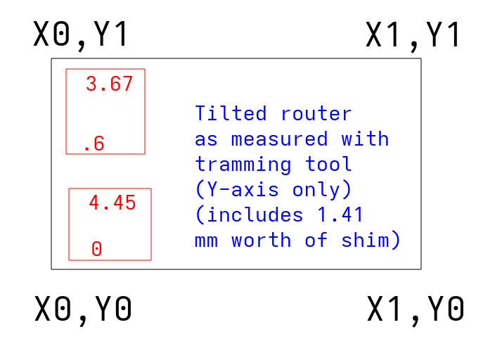
I’ve been chasing down a problem trying to get my Primo trammed. Every time I measure the distance with a tramming measure tool and feeler gauges, the measurements look like the router is tilted towards me on the X-axis side. When I shim the router, either by putting aluminum shims in the top or bottom ring of the router mount, the tilting gets worse:
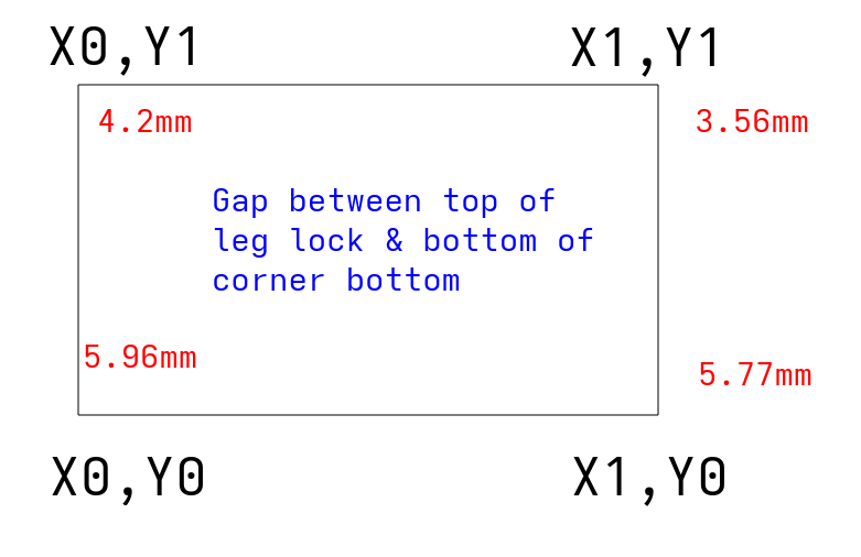
I redid the entire core, trucks, tension, squaring, etc., until I found what I think is my issue - the Z-axis leg conduits are different heights. I went in with the feeler gauges and found these height differences from the top of the leg lock to the bottom for the corner bottom:
I took off the spoilboard (12.1mm MDF), cleaned the hell out of it, noticed a tiny magnet stuck under it, reinstalled the spoilboard, and the issues above persisted.
At this point, should I be trying to get the corners and edges of the spoilboard to level off enough to compensate for the different heights of the Z legs? Given the 2nd illustration above, I’m guessing I need 1.46mm worth of shim at X0,Y1, .19mm worth at X1,Y0, 2.4mm worth at X1, Y1, and enough at the 0.5 marks between each of them to ensure it doesn’t have any bowing.
Does that sound legit or should I be taking some other tack to fix/further diagnose?
Forgive the off-the-cuff reply, but what sort of flatness do you need? Chasing zeros gets very expensive in terms of time, money, and domestic tranquility. I know the tail of that particular dopamine dragon, and it’s tempting to chase it.
Now, if you need it, by all means strive for it.
All that being said, double check for cracked parts (core and tool mount, most likely). Then you probably want to get your gantry as level relative to your work base (what your spoilboard is mounted to) as reasonably possible, then surface your spoilboard with your router. That should give you a spoilboard parallel with your gantry on a large scale. Then work on getting the router perpendicular to the spoilboard.
That’s best case. Yes, shimming your spoilboard to reasonably parallel to the gantry would work. But I’d be tempted to surface your spoilboard as well to make sure the spoilboard is parallel. You only need to skim off enough to even everything out. Any variance from parallel should be localized to an area defined by the geometry of the bit, how far out of tram your router is, and whatever runout your router has. Then tramming your router will reduce that error to (theoretically) the runout of your router. And tramming is most useful if you’re using big bits (like flattening bits), or if you’re doing very fine joinery with little to no post-processing.
Edit: I’d ignore the distance from the foot to corner. Measure from the spoilboard to the bottom of the core with the z-height set to a consistent value. Take out your router, and zero your z-axis is probably the best solution… That’s the important distance anyway
Would you believe I was setting out to surface my spoilboard and that was what kicked all this off? My surfacing bit was tilted a bit in one direction, and looking into why led me to discussions about tramming, and that led me on the long course here.
So yeah, I only need that evenness as long as it allows me to have a nice level surface in the end so I can start doing some pen plotting.
Regarding zeroing the core, should I get the core to a level where it’s flush against the spoilboard, then loosen the Z clamps and redo them so the core stays flush to the board?
At some point a few layers of tape on the router in the clamps will be needed depending on how perfect you want it and how far off you are. Make sure to use a tramming tool, I have a printable one called perpendicularity tester.
Maybe a dumb question but how much tape (or tin can shim material) do I need to tilt the router towards the lower X axis and where should it be on the router? I’ve tried it a few times with a few different thicknesses and locations on the mounts, but it never seems to do anything other than tilt the router further away from the lower X and towards the rear X.
It took a LOT of shims to make any real change. I didn’t bother going in with feeler gauges since these videos demonstrate what I’m running into way better.
This one is with the bed shims in place - you can see the router is tilted towards the right hand side of the screen (lower X axis) and the distance between the screw and the spoilboard changes at all four points of the compass: https://photos.app.goo.gl/qZ9jarbiCobPHcis9
This video is with me stuffing a LOT of shims in the north part of the lower router mount and two or three shims in the south part of the upper router mount. The idea here was to force it forwards. It helps a bunch but it’s not quite there, and I’m not sure how many more shims I can cram in the north side: https://photos.app.goo.gl/ByP13v1bVhjSUwnp9
The way people talk about tramming a router sounds like it only needs a few shims. I think I’ve put in 15-20 shims, maybe around 1.4-1.8ish mm worth. This degree of tilt looks like something is WAY off kilter and I honestly don’t know what to do to fix it.
Should I just keep on trying more and more shims in the router mounts? If that isn’t the answer, I really hate to sound needy here, but can I please get some exact steps on what to do and where I’d do it on an MPCNC? Assume I know nothing about CNCs if it isn’t on the MPCNC docs or on a post I made on this forum.
Or alternatively if the answer is “give up on the Primo, harvest it for parts, and make a Lowrider”, so be it.
Just a sanity check, what kind of surfacing bit are you using? Large radius surfacing bits are several of orders of magnitude more sensitive to tram than damn near anything else you’ll ever do with your router…
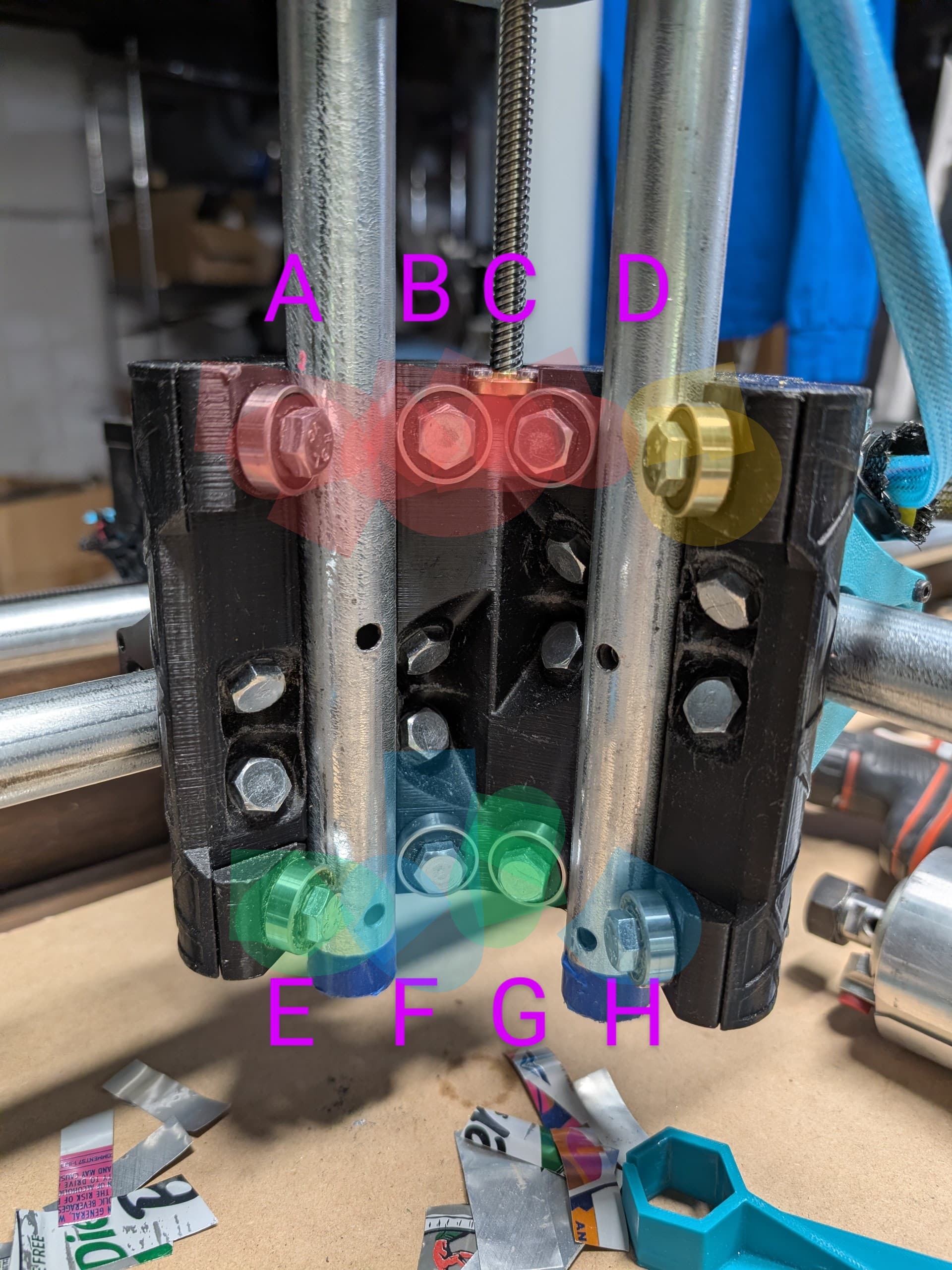
@Tokoloshe / @vicious1 - here’s what my current bearings feel like. All percentages are relative to my perception of how much force it takes to turn the bearing.
Red = LOTS of torque required to turn the bearing. In firm, complete contact with the Z axis conduit.
Yellow = 60-75% torque required to turn the bearing relative to red. In solid contact. Not as hard to turn as the red ones
Green = 30-40% the force required to turn the red ones.
Blue = Easily flicked to move. Not free-spinning, but just baaarely in contact.
IIRC these are all based on getting the nuts and bolts just in contact with the plastic enough so that the nuts/bolts don’t spin when turned with a finger.
Should I be going for equal tension on all 8 bolts or should some of them be tighter than others? I’m guessing the ones in red should not be that tight, but should they be down to yellow, green, blue tightness?
Edit: I loosened all the bolts to equal tension, enough that I could spin the bolts with a thumb and the bearings were just barely in contact. The tilt is still there.
@jono035 - it was a 1 1/8” bit, but after realizing the tilt was the problem, I haven’t tried again. The next best bit I have for surfacing is a straight 1/4” bit, but it’s not made for surfacing so I haven’t put too much stock in it.
Getting the bearings to just that right yellow tightness + 0.96 worth of shim in the 7 o’clock part of the upper router mount + 0.8 worth of shim in the 2 o’clock position of the lower router mount = trammed enough for my needs!