A while ago, I started a discussion about using an Android phone as a touch display. I eventually abandoned that idea after running into issues with the OTG webcam driver on Android.
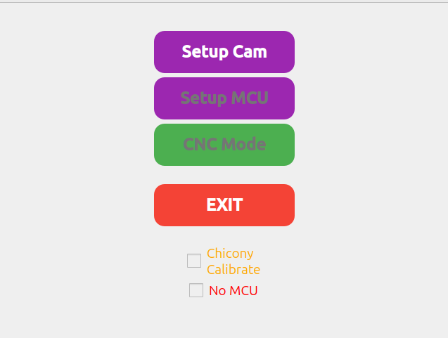
I’m now using a Raspberry Pi Zero 2 with a 640×480 Waveshare touchscreen attached, and I wrote a small GUI for it. The Raspberry Pi is connected to a USB hub, which connects both the webcam and the MCU. Since I’m using USB for communication, I need fewer pins on the MCU. Because of this, I decided to use an ESP32 instead of a Teensy, although they should be interchangeable, as both are supported by PlatformIO. I haven’t started working on that part yet.
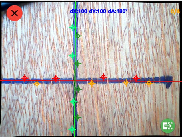
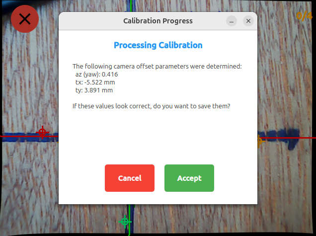
Most of my recent work has focused on webcam calibration. The webcam will be mounted in the top corner of the router. Once calibrated, it can precisely measure marks on the workplane, allowing you to set the origin based on the workpiece or pencil marks.
In pi/scripts/test-gui-laptop.sh you can run it from your laptop with a webcam. Which simplifies the development. I’ve included a brief description in my README.md, which can be found here:
Looks great.
Can you explain a little bit more… the WEBCAM is for what?
The Pencil Cross is the Master on your WOOD.
And then you go with the Webcom over it.
Best possible looking, and you make some measurments to check how many mm or angel you are wroong from the MASTER PENCIL CROSS ?
And you ESP32 is only for GUI and DISPLAY and they talk with some more Pins to the Teensy to bring the Measurement Result as a OFFSET ?
Here I made a PDF to explain my approach a bit better. I hope it helps. I implemented so far the camera calibration and the GUI basics. Let me know what you think.
I have all peaces for the CNC Router here.
All 3D Parts a printed.
What i miss…. TIME
I have some projects here before, but this is a nice ADD ON.
Do you have ideas to bring these Parts also in 3D house, to protect them?
Any Ideas for printing and mounting?
Maybe i can start to build my cnc directly with this add on.
Can you write all parts here, what you have used for this?
Display, ESP32 wich PI…
It will take some time. And actually I have to build me also a router first. But when finished I will make it as easy as possible to modify the existing setup. Especially for the Teensy. I simply prefer the ESP32. Just because it’s cheaper. But software wise they should be interchangeable. So you don’t do anything wrong when you finish yours for now. But I definitely will give a note when I finished my version.
Also the mount for the camera has to be flexible for different models.
Hey, you also seem to be interested in the idea. That’s great.
In the moment I’m still in the planing phase. So I think the Touch-Display would be an upgrade which is definitely beneficial to the project. But with the camera and the camera position I’m still unsure.
So maybe you could help me brainstorm. Because to use the camera only to mark markers on the workplane doesn’t add many benefits. Because it also might be done with a square ruler on the workpiece. But I saw for example the Shaper Origin has a camera to survey the cutting area.
So you could actually see where you are cutting. That would be a great thing I guess. My only concern would be that a lot of dust will build up at the lense.
Maybe you have ideas on how and where to install the camera.
Hey,
here is a tear down Video from the Shaper.
You can see the Camara by Minute: 13:31
make Pause and take a look what you see.
Left part over his Hand the black one.
That is the Camera Modul.
You see 3 white LEDS the smal DOT is the Camarea and then comes the next 3 LEDS.
At this position, you have not so many DUST there
14:20 comes the Info it is a standard smart phone cam.
And in this Video you see, in 7:37 make Pause, the LED’s where on.
The camera on the Shaper Origin looks NOT where the rotating router is.
He orientated only the camera picture on the domino stripes, to check where it are.
Start this Video on 2 Minutes or take a look complete.
He makes also MARK POINTS on the wood, for orientation.
Yes nice will be to take a look where the router are working.
BUT there is to much Dust.
OR
You must make a small blower on that point to blow the dust away from the camera.
Maybe with the vacuum cleaner.
Hey many thanks for the videos gave me a much better understanding. I think I will continue to build my router but install a touchscreen. When this is done I will consider the camera and things around it.
I just wanted to jump in and say your approach looks good to me. I have calibrated cameras using open cv for uncrewed ground robots (driverless cars) for almost two decades, so I know a little bit about it.
Instead of an esp32 or tenant, I would try to make this more expandable. If you were connecting to a “standard” cnc machine, all the controls you want would be available through gcode on the usb. Making a common interface isn’t easy. But it will be needed for the project eventually.
I think the use case isn’t perfectly clear, since this is a compass and not the origin or low rider. I think your plan is to:
Mount a front facing camera on the compass.
Put a checkerboard in front and do the intrinsic calibration. Then do some cutting to fine tune to the tool head.
Use the pi to set an origin (possibly with rotation) in the image.
It’s that about right? The part I’m most confused about is the final process. Maybe I just need to read a little more carefully.