OK, I am finally almost there. It’s taken much longer than I wanted due to other commitments. Today I am finishing crimping those pesky Dupont connectors for the Jackpot switch connections, then the carriage is finished.
Some build photos will follow shortly of by 8x4.
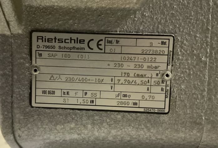
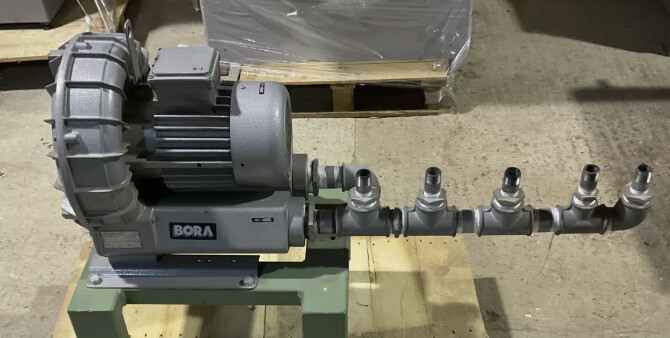
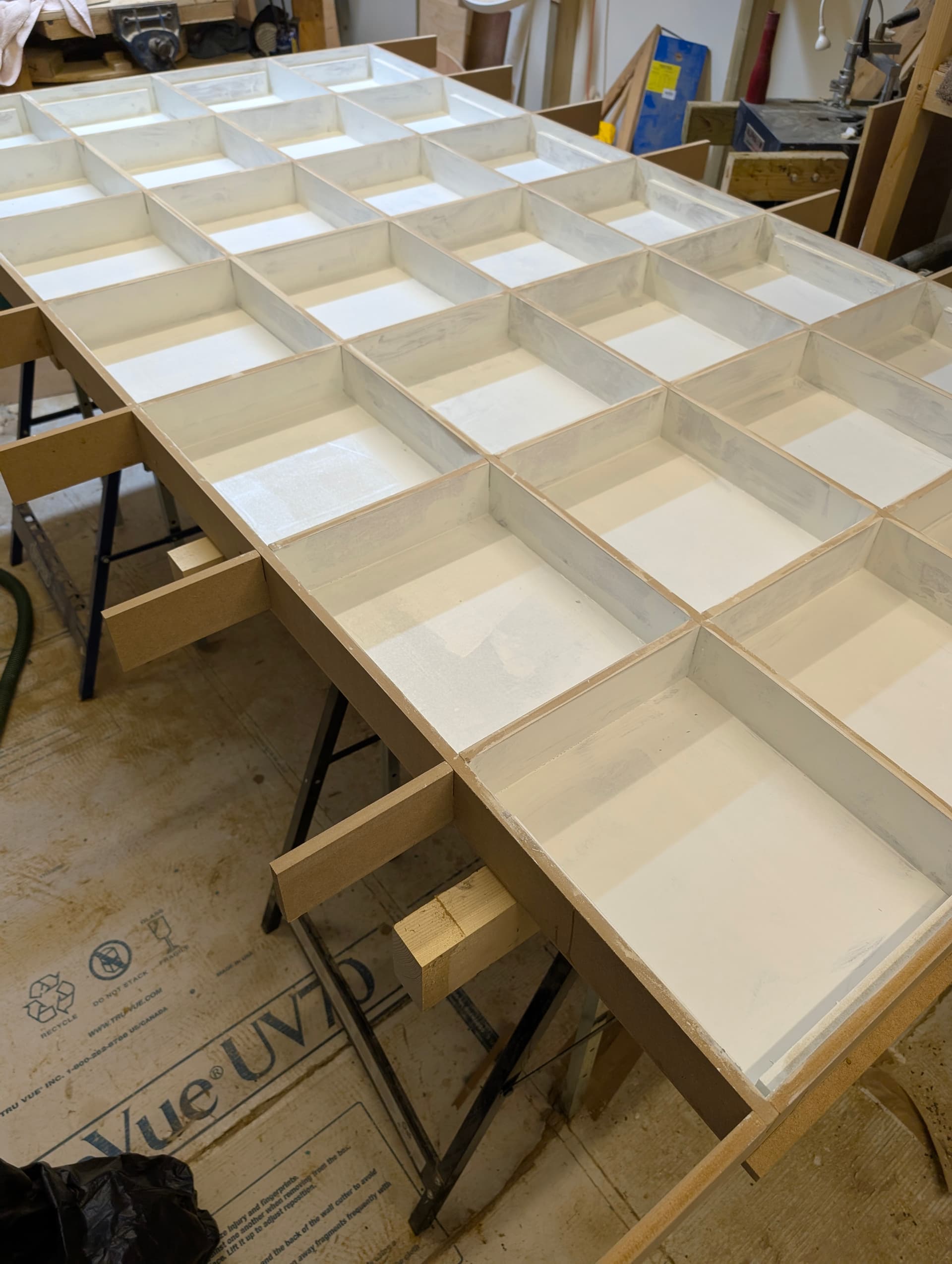
The Torsion table is laid out flat waiting to be screwed/pinned and glued up. I have made it from 12mm MDF. I have also bought a 2nd hand 3phase 1.5kw vacuum/blower that already has a manifold with 5 outlet pipes attached. I am in two minds whether to make a 4-zone or 1-zone bed, tempted for 4 zone since the manifold is already there.
I am concerned about the torsion box distorting when at full vacuum, the pump specs say the pump will go to 130mbar or 2psi of pressure, assuming minimal vacuum loss.
I am looking for advice. I assume for smaller parts using one zone, there will be less losses and therefore a greater vacuum. Is there a danger of the torsion box sides/top/bottom distorting?
To try and minimise losses, should I carve channels directly into the top surface of the torsion box for the sacrificial board to lie on? Since its only 12mm MDF, how deep could I carve the plenum channels? If I seal the edge of each zone (1 or 4 of them) with neoprene how deep should I make the gasket channels and what thickness of gasket should I use? Would a 5 mm gasket channel with a 7mm or 8mm gasket be OK?
I’m not sure I’d be that concerned about warping, but what’s the max cfm on that pump?
With a vacuum, you’ll have losses through the MDF. Everything except for the top surface needs to be sealed extremely well to stop it.
Commercial vacuum tables on expensive CNCs have pumps that go north of 200cfm.
I don’t know what the true leakage of 1/2” MDF is, but that’s what I’d be looking for to see what size and how many zones you can run on that pump and have it able to actually hold parts
Following your post with intrest, please upload a couple of pictures. Mi vacuum table is using a 3hp/2 stage pump. (I was using a big vacuum cleaner and it worked perfectly for what i do (acm sheets) it holded them really flat (but i was using also toe clamps on the sides (we have some power outages frequently)
The vacuum is 230mbar (not 130mbar) or 3.3 PSI. Volume is 170m3/hour or 100 ft3/minute. Not quite the 200ft3/min you mention but its a start.
I am hoping to seal the entire torsion box, (except the Plenum surface) with 2 coats of polyurethane paint. All edges and outrigger spars will also get a double coat so that vacuum losses are kept to a minimum.
Hi Cesar,
Ive your posts with much interest during my build as one of my first projects is for a friend who needs three large tanks (6ft x 4ft x 6inches ) from ACM. I made him 3 smaller ones a year ago using a trim router, ruler, and vbit that I made by grinding the tips flat as an improvised ACM grooving bit . It was tricky by hand (especially on the ground in a gravelly car park). I had to use silicone to plug the odd gap here and there.
I intend to also cut ply and MDF at a later stage.
Thanks for all your posts in the forums, they have been very informative during my build.
I have one of those pumps (Seitenkanalverdichter) as well. You can find pictures of my suction table in my Ghostrider thread. It works well through MDF, I cut the grid in plywood though as to not lose suction. Here’s a video when it was still an MPCNC with a different base plate from MDF I sealed with watered down wood glue.
I used 6.30 mm deep with a 1/4 inch diameter bit and these gaskets: gasket
A halh inch mdf as a bleeder board ( i removed the skin from both sides first using the vacuum table. And placed 1/16" holes every 10mm over the inside channels to help the vacuum) i use a filter in my pump but i really don’t use it for cut operations just v-routing -thats when i beed the sheet to be very flat-
-edit gaskets only in the most outer channel
You should seal tht top mdf sides with glue/polyurethane
I’ve book marked your link to the cheap V-bit, thanks, Ive already bought a specialised ACM vbit ( ~$15) I will buy your cheaper version when mine is goosed.
I hadnt really thought of the bypass and filter as I thought there should be very little dust sucked in the torsion box as it would be a sealed chamber but if I add a bypass valve I guess it it will be needed, again thanks for the headsup. The pump should arrive tomorrow. I will order after I check pipe/thread sizes. The 5th outlet on the manifold will be a good use for the bypass valve.
Thanks for the link, but was there a typo or link problem in your post, a 6.3mm deep channel for 1/4inch high gasket would mean that the gasket is not above the suction surface I think?
How much does that sort of gasket tape compress ? Would 1, 2 or 3mm proud of the surface be sufficient without risking the ACM being held up and creating high spots due to insufficient hold (push) down force?
I thinks its amazing that 0.05mm works. The commercial CNC machines, from memory seemed to have a 1 or 2mm, but its been a while since I’ve seen them so I am probably wrong.
What speeds (RPM) and IPM or mm/sec do you channel your ACM at? I assume its just one pass…
The torsion box has its first skin attached. I have painted the inside surfaces with old tin of gloss paint I picked up for a $5.
Tomorrow I intend to drill holes in the spars that seperate the skins so that vacuum/air can move around under the hole surface but I am having second thoughts on the design.
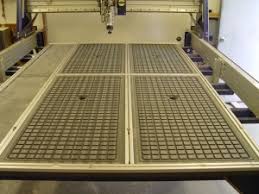
I am intending to machine grooves into the top surface of the torsion box to pass vacuum through to the sacrificial board that the sheet that will be cut sits on. Will this weaken the top skin of the torsion box? I intend to use 12mm MDF so it’s not much to work with, this way the whole torsion box develops a vacuum.
Or should I use the torsion box solely as a stable surface and perhaps add a 18mm MDF sheet on top of the torsion box and mill a square grid of grooves into this, seal it and then connect it through a centre hole that runs though the torsion box to the pump plumbing underneath? a 12mm sacrificial mdf board would then sit on top of that.
I’ve searched the internet for the vacuum torsion box design but dont find much on it which is ring alarms bells in my head.
How do people use vacuum beds with the LR4? any ideas, words of warning?
I’d say keep it separate. The skins of the torsion box don’t actually have to be very thick, technically speaking. They are providing rigidity by aligning all the internal spars using their flat-plane stiffness, like how it takes almost no force to bend a piece of paper but lots of force to pull it apart. They’re also supporting any point loads on the surface so that the load can be distributed out to the spars so you don’t ‘dent’ the tabletop of have local sagging in between spars. Those are actually 2 different tasks that get combined into one by having a thicker top, usually.
The trick is that you need to have good joints to transfer the load through the structure. If you’ve got a thick skin you can just sink screws. If you’ve got a thin skin then screwing gets difficult because you’ve got less strength to resist having the screw dragged ‘through’ the skin, gouging a path. So the thinner the skin, the most you need a fixing solution that’s valid for that material. 18mm plywood or MDF and you could just use screws into each section of the spars. 5mm plywood and you might be ok with more screws but might want to use glue. Thinner than that like 2mm or something and you would want to start gluing or using a ton of brads/small screws etc.
Thinking about it that way should hopefully make it clear what will be acceptable or not with the skin surface in terms of cuts in it etc.
You could do torsion box with thin (~5mm?) skin on top then an 18mm MDF vacuum plate above that. You could do it with a thin skin on top then a sacrificial 12mm ply and then the vacuum plate. You could do it all-in-one where the top skin is the MDF vacuum plate and just plan to rebuild/replace if needed. I think replaceable top skins work best when you’ve got something thick enough to fix it using just screws, or a plan for how to get it apart. If you’re doing a sacrificial work surface with the skin below that then I’d go for a permanent thinner skin with a lot of fixing and a replaceable work surface with way fewer fixings.
As for the vacuum aspect, I’d definitely do those as separate things. I don’t think you’d be wanting to draw a vacuum onto the inside of the torsion box because it’ll slow down the rate you can pull a vacuum quite significantly, which is important for pulling things into line. The higher your flow rate, the more force you can apply to a joint that’s not completely sealed which will pull it down and seal it. The more volume you have to evacuate, the lower your flow rate will be because you’re drawing down a bigger space etc.
Thanks Jono. I have already bought two 12mm MDF boards, one was going to be the skin, one was going to be placed on top as the sacricial board. I was going to carve out a pattern like this on the skin….
I have a 100ft3/min pump and I calculate that the internal volume is around 8ft3 so I don’t mind waiting 10seconds or so for the board to be gripped (assuming I can get it sealed sufficiently on the sacrificial layer)
I am planning to skim the surface of the sacrficial board on both sides what ever design I go with.
The spars are 12mm so I don’t have much to screw into as the inside of MDF is pithy. I used some scraps to test how good a pull I would get using 35mm x 3.5mm screws and I got almost zero bite. I didn’t drill pilot holes, I could try again with longer beefier screws and pilot holes but because it’s 12mm end on I expect much of the strength to come from glue.
My main questions currently are:
Do you think that the vacuum torsion box with just a 12mm plain MDF top skin (no routed air channels) and a 12mm sacrficial board allow enough vacuum to hold the workpiece?
Would a 18mm top skin with a plenum grid machined similar to the photo above with a skimmed sacrficial board on top of that work better?
Is that at vacuum or in free air? Have you got a link to that, it must be an absolute monster. The one I have for degassing epoxy is ~10cfm. It slows down as it starts to pull a vacuum so I don’t know that the 10 seconds will stay that way, I’d guess it might be more like 10 seconds to drop the first 4-5 psi, then another 20 seconds to drop the next 4-5 psi etc. That’s roughly how ours works with what I think is a 30L pot.
12mm should be tons, I would definitely drill pilot holes all the way through once the skin is in place, even if just to secure things. There shouldn’t actually be much load in the direction you’re screwing it in, the screws are there to essentially keep the spars upright. It’s relatively small load and ‘sideways’ on the screw. I’d also screw it so that I could check for bulk flatness before gluing it all up. Obviously surfacing it will sort some of it but it’s better to have it flatter to being with so the surface is closer and the rails and co-planar. That said, it’s pretty easy to add runners for the rail/running surface etc.
So relying on the vacuum straight through the MDF? That I’m not sure of. I know air flows a little in the core of the MDF but I think the outer surfaces are pretty sealed. That’s reaching the end of my familiarity and I’m just going off rough memories of what I’ve read here before.
I would certainly expect something like that to perform better, I would say it’s more a question of whether it’ll perform better enough to be worth the hassle.
If it were me, I’d be making a smaller scale test setup and seeing how that performs. Maybe make a 1’x1’ / 300mm x 300mm square with each option and see because it should be pretty linear… For flexible materials, I think it’d ‘feel’ the same in the smaller case because it’ll be more about the force per area rather than the overall. If you wanted to you could also try to temporarily seal the table and draw a vacuum on that to see how that changes the ‘bite’ of the table and how long it takes to draw a vacuum.
Thinking more about our vacuum pot and the 10cfm pump, that’s probably a similar scale. Our 30L pot is pretty close to 1ft^3, so you’ve got 10x the area but 10x the pump. I think we were looking at closer to a 30s to 1min draw down on that, but obviously that would be a steady ramp up in the force on the workpiece.
Hi Jono, there should be pump photos further down the thread. If it’s a minute to reach max vacuum I can wait. I am not doing production work.
I am very impatient to move on, I think I will buy a 18mm sheet, glue and screw it down today, when it’s assembled I will cut the grid to help distribute vacuum.
Perhaps just another few cups of coffee and some reading and googling before I start