Tool settings for flat tipped v-carve bit

Pretty sure the tip offset is for chamfering with a pointy endmill. Yea, that’s what it’s for.

1 Like

Well, bummer… it’s a really nice, versatile bit. It’s just a struggle using it with EstlCAM.

1 Like

Just do the negative offset. I think you will be fine

Does that just apply to chamfering/rounding/profiling? I would like to use this as my carving and pocketing tool. There is no smoother pocketing than what this bit can do. Ultimately, I want to eliminate the bit change. With the bit change, it never cuts EXACTLY where it should between pockets and carves.

So yes it does program to radius from what i understand, but i suggest trial. I do not think it will matter

Is @christian-knuell still around here? Maybe he could give some pointers.

2 Likes

As Jamie said, tool diameter is always the largest possible cutting diameter. Following your link I see a 20 degree bit (not 15). Both Center and Tip Offset only work when the tool is used as a secondary chamfer/radius tool (the bottom/rounding image seems like it should be bearing post height).

Using a Finishing allowance of .75mm (1/2 your tip flat) should work, but I’m not sure if it will because the preview screen paths don’t move .75mm like they do on the edit screen.

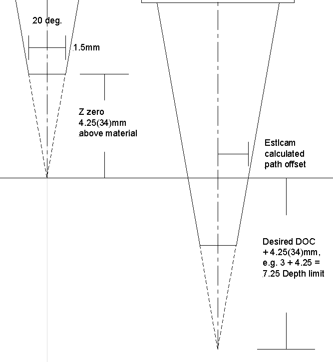
To get Estlcam to offset the paths the correct distance for a 20 degree bit with a 1.5mm flat, you could set Z zero 4.25mm above the material and add 4.25mm to your desired Depth limit.


(…above corrected .75 > 1.5 flat)

While the hole and part Finishing allowance (w/o a finishing tool) will only change the offset (resulting in a bigger or smaller hole/part), the carving Finishing allowance only adds a finishing path/pass (image right) that is identical to the the one(s) above.

3 Likes

6 months later, I’m finally getting back to this bit. I’m determined to make it work. The tool changes are brutal - throwing off the machine just enough to destroy the project. I really like @dalrun 's solution. This is however a 15 degree bit, not a 20. The link I provided is for the four-pack, which includes a sharp 20 deg bit, but the one in-question is this guy:

This seems like complex math to come-up with the correct adjustment to the z-zero. For now, I’ll go with some trial and error figures until it looks right. I’m not after precision - I make novelty signs that should look decent. Thanks for the z-zero suggestion and the desired depth adjustment. I’m giving it a go.

Thanks ChatGPT, you help me not have to think anymore (Society is doomed):

First, we need to find the radius of the base of the cone by dividing the diameter by 2. So, the radius would be 0.7mm.

Next, we can use the tangent function to calculate the height of the cone:

tan(75 degrees) = height / 0.7 mm

Solving for the height, we get:

height = 0.7 mm * tan(75 degrees)

Using a calculator, we can find that the height of the cone is approximately 2.804 mm.

Therefore, the height of a 75 degree cone where the base has a diameter of 1.4mm is approximately 2.804 mm.

It worked. Here’s how I set it up:

Using ChatGPT as my universal plain-English calculator, I asked it for the height of a 75 degree cone with a 1.4mm diameter base. A 15 degree bit is essentially a 75 degree cone. The answer is 2.8mm.

My thickness probe is 1.3mm. In the startup gcode, I subtracted 2.8mm, which gave me this:
G92 Z-1.5

On my project, I want a 3mm depth. I added 2.8mm to that for 5.8mm

BAM! Perfect cut, the first time. I just need to remember my wonky G92 Z setting when I change the bit.

from my experience chatgpt is a 50/50 chance to be right. It is however very convincingly wrong.

I may be missing something here. I just used an Isosceles Triangle Calculator (Isosceles Triangle Calculator) to confirm my earlier drawing and get 5.32mm (VS 2.8) for a 15 degree bit with a 1.4mm flat.

Well, like I said. Society is doomed.

I’m pretty happy with the results from my incorrect numbers, but I’ll give the real numbers a whirl to see if there’s any improvement.

1 Like

You know, I think you are trying to compensate for the missing part of the tool. It looks like your tool change is the problem. Are you using a metal probe for tool change? If so, 2 things come to mind. A) have a thicker tool probe, or b) make a spacer for below the probe. But the best thing is to figure out the tip offset. That would fix it. It will involve testing though. But it will let Estlcam work correctly.

The amazon pic shows that tool is not completely flat, so that may be the difference. That is one odd tool and not sure why they made it that way.

The tool change is enough of a disruption to the gantry, trucks and the unit as a whole when moving the router, cranking on the lock nut/etc, that it is often never exactly in the right x/y/z position when resuming a job - even with the dual end-stops and z-block. My Primo is a few years old with some heavy use, that maybe it’s simply worn-out. I bought the new Low Rider, but haven’t pieced it together yet.

I like this bit because it provides sharp/clean carves and has that 1.4mm flat for smoothing some of the larger areas. Tool changes are a pain, and I’ll avoid them if I can.

Curious how far you’d go to avoid a tool change, already seen…

I’m guessing that the “point” at the bottom allows it to plunge.

Edit: It also appears the the point could also be used to “etch” into a surface.

@azab2c , I imagine that the router/motor required to accommodate automatic tool changes would be incredibly expensive. But, I’d consider it. Especially for the LowRider where I might be carving a VERY LARGE project over the course of hours.

@ttraband , I set a plunge angle on any tool with a flat tip. It seems to work well.