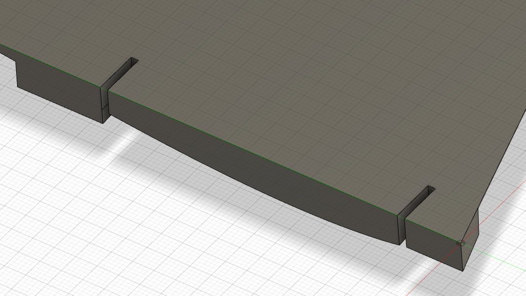
So I have a groove I need to cut and am using Fusion 360.
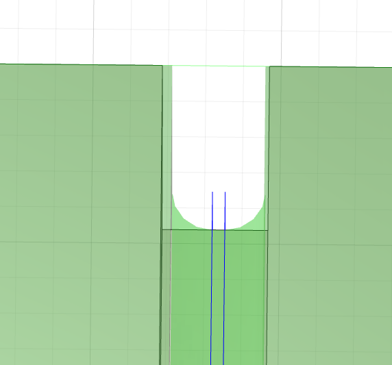
the groove gradually gets deeper (ramped surface) and is 4.216mm wide.
I am using a 3.175mm (1/8") bit and am currently using a parallel tool path.
I would imagine that only two passes would cut this.
However when I tool path it I get this result in the preview
I’m a beginner when it comes to tool paths, but I believe you will get closer to what you want with a 3D Contour or a 3D Ramp tool path. Parallel tool paths are typically used for finishing. Just judging by the diagram, you parallel tool path is taking a huge depth of cut.
@robertbu - I’m cutting XPS foam and it is not a very deep cut. So I chose parallel thinking it would just be a quick cut. I can look at the other you mentioned.
I’ve run into this when I’ve used the parallel tool path as well. I can’t remember how I dealt with it other than to do a regular cut first to remove the bulk of the material, then using the parallel tool path to smooth out the surfaces. (I was cutting curved bottom slots for holding drill bits.)
I just did a quick test since I’m curious. If your grooves are modeled with flat bottoms, you can use the Pencil tool path to make the down and back cut you are expecting. 3D Contour also worked for the radial cutting but left the bottom stair stepped .
Without having the model, I cannot test any “right” way of making it work, but there is hackish way to make it work. Create a sketch at the bottom of your slots, project the slot outline on to the sketch. Then you can use the sketch outline in your CAM to define your tool path.
Edit: Or you can use the top of your slots for the path and redefine the bottom for your 2D contour cut or even a negative stock to leave. Still hackish.
Edit2: If you are trying to mill just these slots, you can first click on the path at the top (which will select the path all the way around the part. Then click and hold on the highlighted path. This brings up a new menu that allows you to select an open path and then select just the three edges to add to the path. You will have to do this separately for each slot. Then you can set the bottom height to ‘Model Bottom’ instead of ‘Selected Contours’.