I’m positive this question has been asked before, but I’m so new to this that I can’t quite figure out how to word what I want to search for.
Here’s a scenario. I want to cut out a rectrangle with a 1/8 or 1/4" bit. Within the rectangle I want to create lines using a .6mm bit. Think fretboard, since this is where I’m going with this.
I can’t figure out how to tell etlcam that the lines are to be carved with the .6mm bit not the 1/8" bit. I only see where I can specify the ‘finishing bit’ for those lines.
What I think will happen, based on the preview, is that my Primo will cut the lines with the 1/8" bit and then go back and finish them with the .6mm bit. What I really want is .6mm lines.
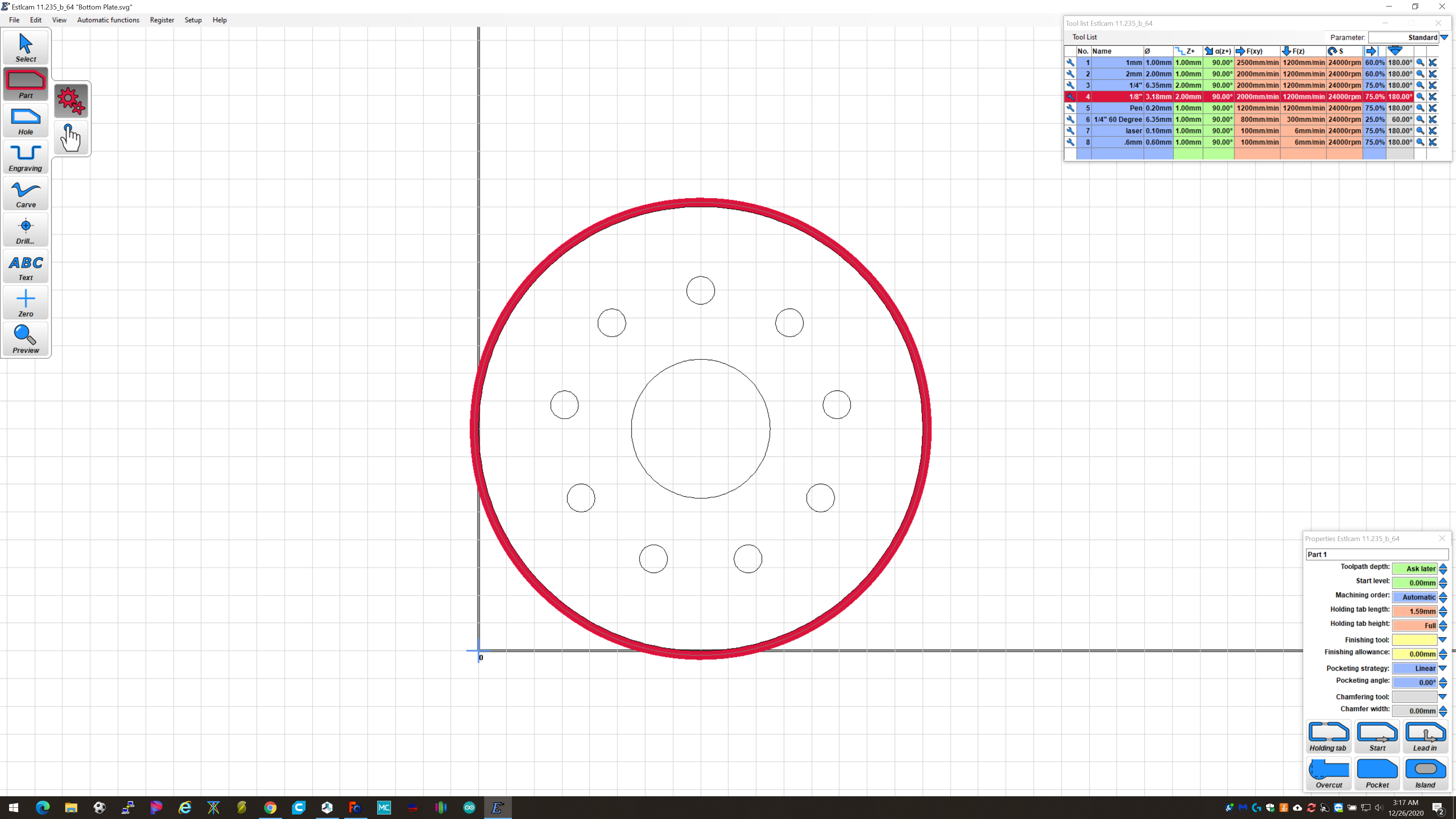
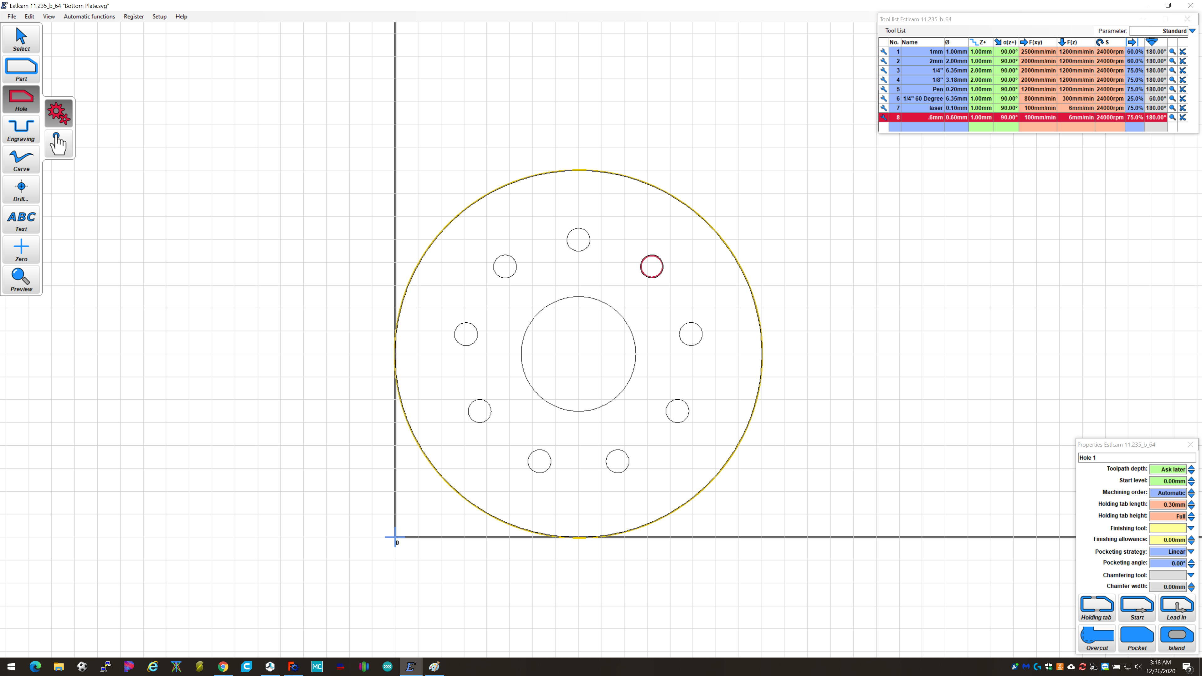
What you need to do is select the 1/8" tool from the tool list, then select the path you want to cut with that bit. Then, select the .6mm tool from the tool list before selecting the paths you want to cut with that bit. When doing your path selections, whatever bit is currently selected in the tool list is the tool it will use to cut the path you are selecting.
I believe so. I use Estlcam directly to my controller and it goes to a pre-determined position when the tool needs to be changed. I think when you export the gcode, it does something similar. I would make a simple run with a tool change and air run it to see how it will actually behave.
The G-code that gets added for each tool change is in Setup : CNC Programs : Texts : Tool change. I believe the default is M06 (tool change), some controllers may need M00 (pause) instead. The default G-code will only stop the spindle and raise it to the clearance plane. If you want it to automatically go someplace for the tool change you can add coordinates to Texts : Tool change (between M05 and M06). If Estlcam is running on the controller, Setup : CNC controller : Length sensor fixed location is another option.
As you and Dave L explained, I was able to edit the Setup->CNC Programs-> Texts → Tool Change and have ESTLCam move the bit to the left/front spot and move the Z up so I can swap out the bits. Now I can’t figure out how to get the Z0 plane set up the same for the next bit since one might be shorter/taller or inserted into the collet at a different height than the first bit.
I’ve been trying to use a fixed mounted probe, but I haven’t been able to figure out how to use the delta distance between the two bits to update the Z0 plane. I’m using Marlin and I’m thinking I can’t do that with that firmware (not access to variables).
Does anyone know if Estlacam can save a file based on the toolpath (or one file for one bit and another file for the other bit)? That would be another workaround I could use.
How do you set your Z0 now? If you have the TinyTouchplate from the V1 shop, or another touch plate solution, you can probe the bit length and send a G92 command but only provide the Z parameter. This will leave X and Y alone but correct Z for the new tool length.
When touching off from the top of the workpiece, you may want to save a corner to use that doesn’t get cut until the last bit change so that your reference surface stays the same throughout the whole job. I think folks who do a lot of tool changes tend to probe the bit at a known spot on the actual spoil board rather than the surface of the work for this very reason.
Machines with automatic tool changers often have a table of tool offsets, but I think these only really work well when the tool is in an indexable holder so that the length is exactly the same each time it is mounted. I wouldn’t try that when manually changing bits in a standard router collet. Probing the bit length is needed in that situation.
I don’t know how the Estlcam controller tool length sensor works, but with anything more than a couple of tool changes the one click Z zero reset is quite handy. After initially probing the sensor and material top (storing the zero offset?) clicking the length sensor icon (after a tool change) automatically probes the sensor plate and resets Z zero (plate zero +/- stored offset?).
That known spot on the spoilboard can also be the X,Y origin to simplify machining multiple workpieces (no manual jogging required) and two sided machining (with the flip happening during a tool change). My preference is behind and/or to the side of the material, as close as my grid of mounting inserts allows.
Thanks. I’m not using an Estlcam controller. I played with it some more and since I’m using CNCjs as my g-code sender, I’ve figured out a workflow that works - using the different Marlin Workspace Coordinates (ie: G54-59 that CNCjs seems to support). I just edited the Estlcam commands for a tool change to first change to the G53 machine coordinate system, move to X0Y0, pause to allow me to change bits, resume, and then change back to the Workspace Coordinate system I was working in (G55) and then move to X0Y0 and it puts the bit right over the front/left corner of the stock that I’m working on and that I’ve set as zero within Estlcam. It then pauses so I can put my XYZ probe on the corner, I resume, it zeros the Z with the new bit, pauses again, so I can remove the probe, then resumes again to finish the job (until the next tool change). This is what I’ve put under the Setup->CNC Programs-> Texts → Tool Change part o Estlcam:
G53
G0 Z60
G0 X0 Y0
M0 ("CHANGE BIT TO: "< n >) ; pause and put notification of which bit to change to
M108
G55
G0 X0 Y0
M0 (“SET UP PROBE”)
M108
; Touch off Z
G38.2 Z-20 F300 ; perform z-probe
G92 Z6.6 ; Set Z to thickness of touch plate 6.6mm in my case
G0 Z15 F500 ; raise 15mm
M0 (“Remove probe - READY TO RESUME JOB”)
M108
I do need to explain that before my job is run, I get into the Workspace Coordinate system (G55) and use my XYZ probe to zero out all three axis at the front/left corner of my work stock with the initial bit. One could , if using the same spot for every job, do a M500 and save this in Marlin’s EEPROM so when you turn it off, and then back on, that location is remembered when you get into that Workspace Coordinate system (G55 or any of the others G54-G59).