The Red, Gold & Green Machine

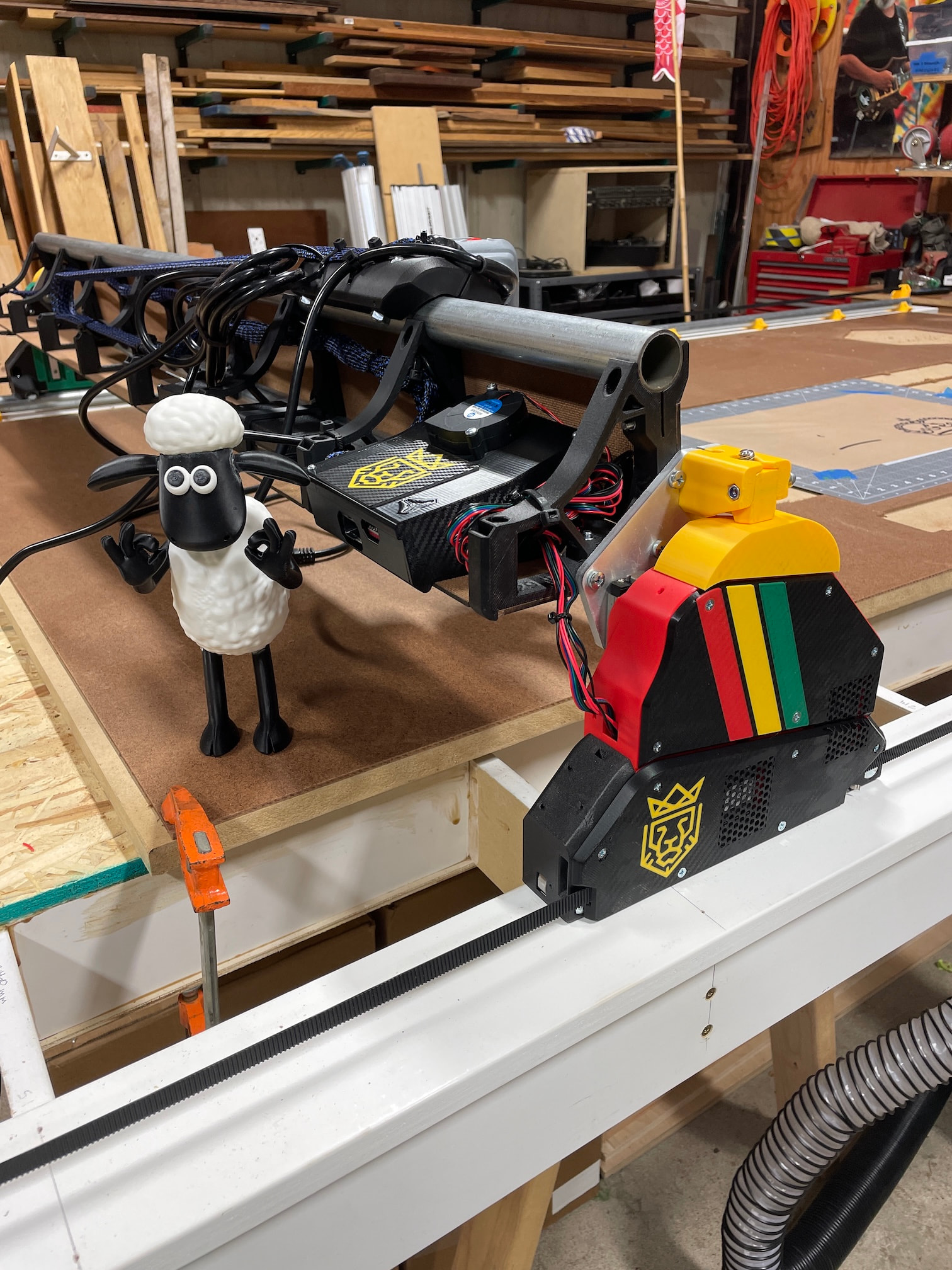
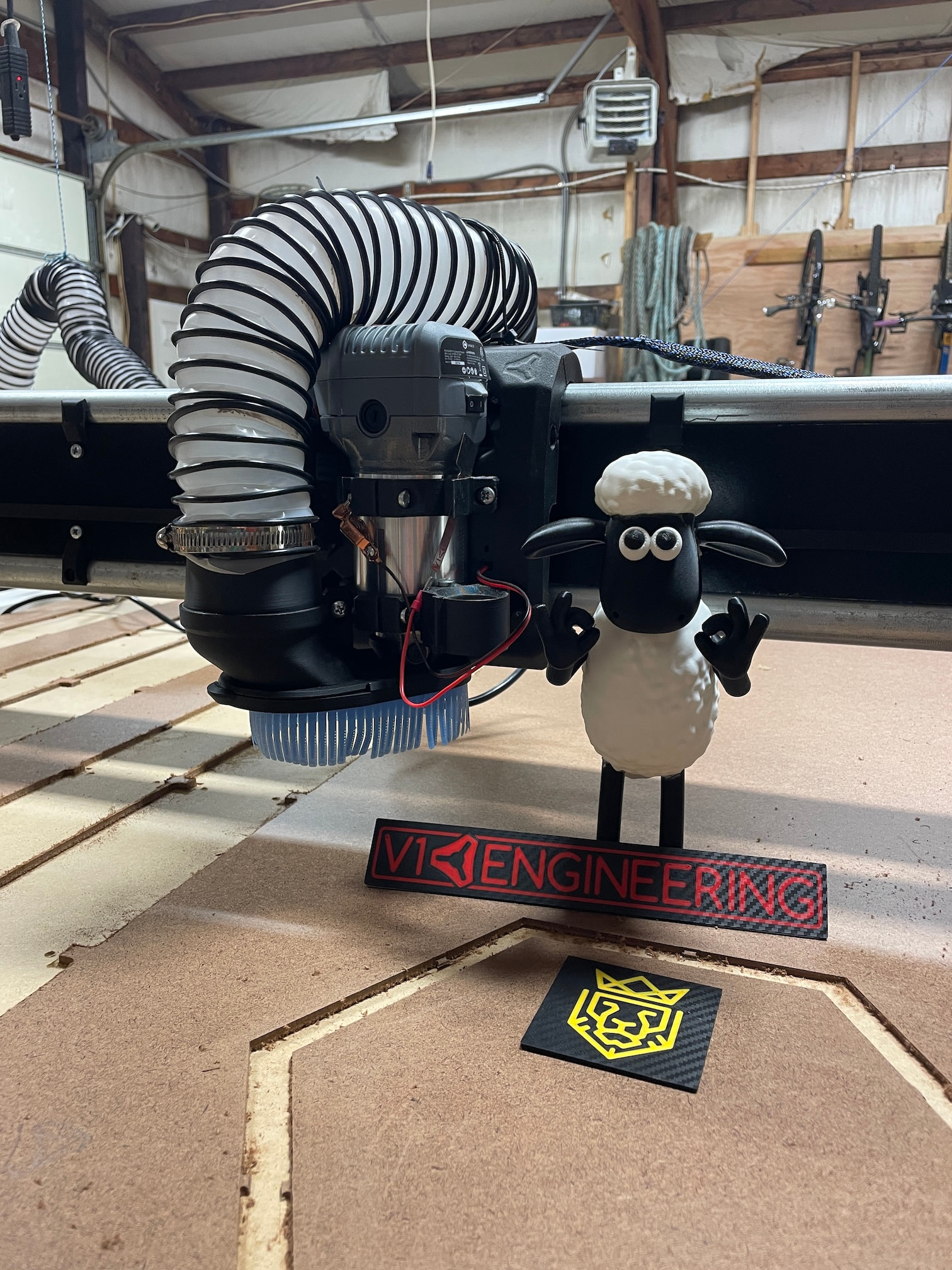
Presenting the Red, Gold & Green Machine! After months of research and weeks of building I’m (mostly) finished with the build and (almost) ready to start cutting some wood for projects.

My most sincere thanks to @vicious1 for sharing this amazing project with the world, and designing a quality, affordable and accessible CNC machine that I could build at home. Thanks also to the generous and helpful community here in the forums, without your assistance this project would not have been possible.

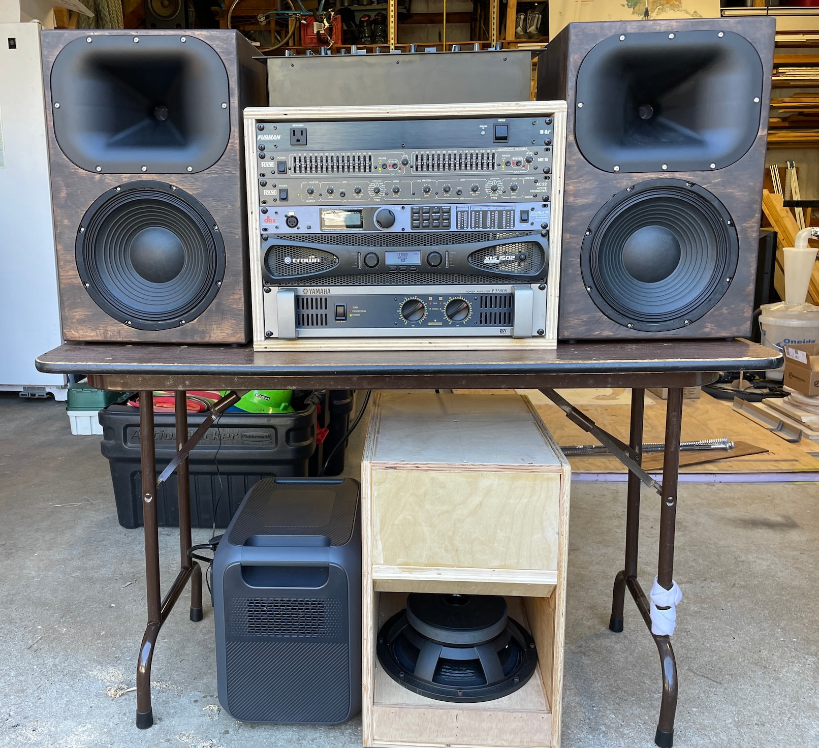
Why Red, Gold & Green? My primary motivation to build this machine is to to use it for speaker building- specifically large PA speakers for playing reggae and dance music at events and parties. Red, Gold and Green are the colors of the “Rasta rainbow”. Even though I’m not a true Rastafarian myself, I love reggae music and its usually what’s blasting from the speakers in my shop anytime I’m working on projects. This machine is inspired by, and largely built for, speaker building and my love of music.

My CNC journey started about five years ago when I backed the Maslow 4 project on Kickstarter. My motivations were the same, at the time I was just getting into speaker building and was fascinated by the world of hobby CNC machines. After much trial and error I did successfully build a nice pair of speakers with the help of the Maslow, but in the end I discovered that it wasn’t the best machine for my specific needs.

I spent a few months online researching all the available options, lurking around the forums, and getting deep into the Reddit comment sections before deciding on the LR4. I’d always wanted to get into 3D printing and building an LR4 seemed like a good excuse to get a 3D printer and dive down that deep rabbit hole. I ordered a Bambu P1S and spent another month learning how to use it before I ordered the LR4 parts kit from V1E and started this project.

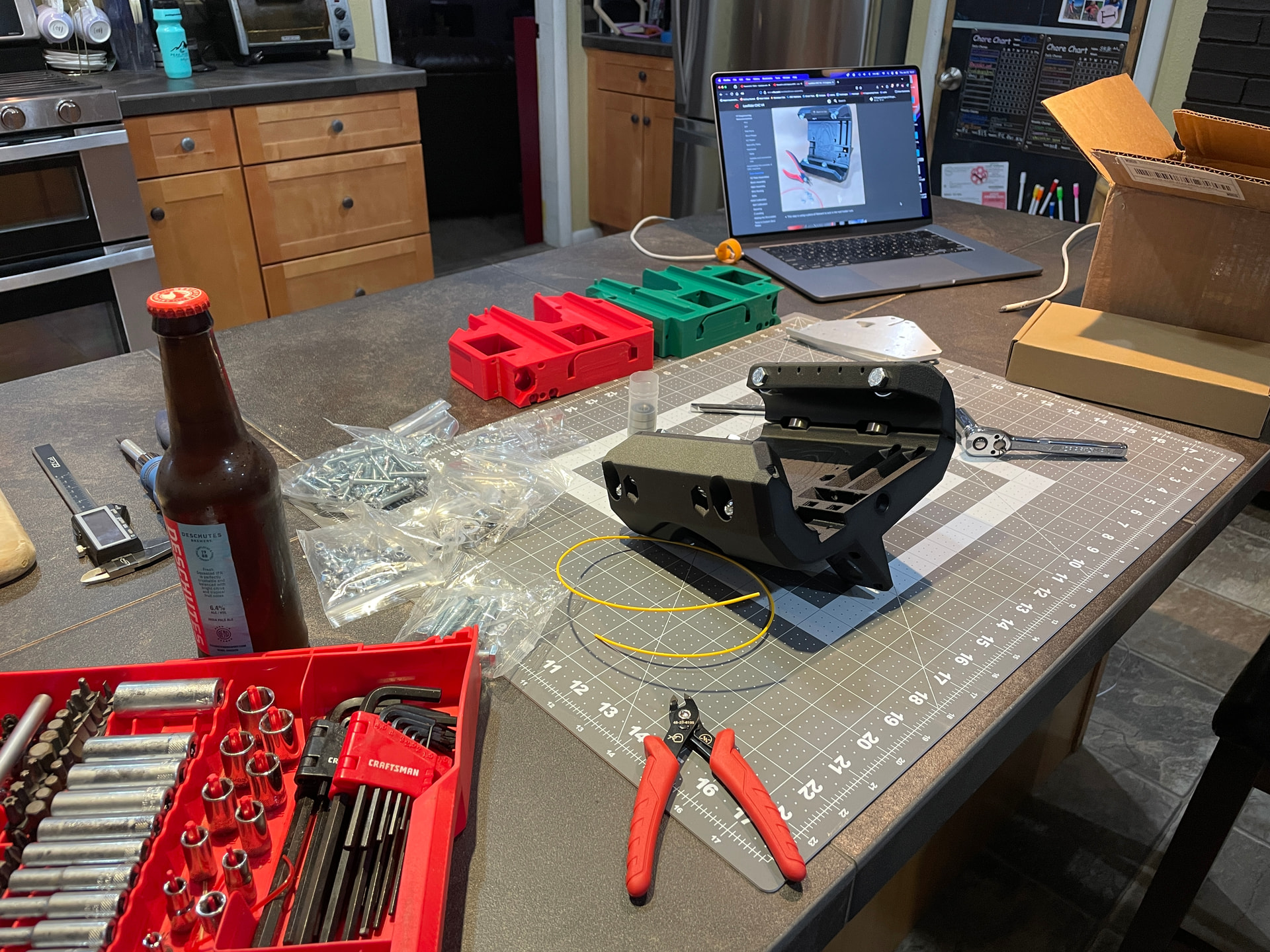
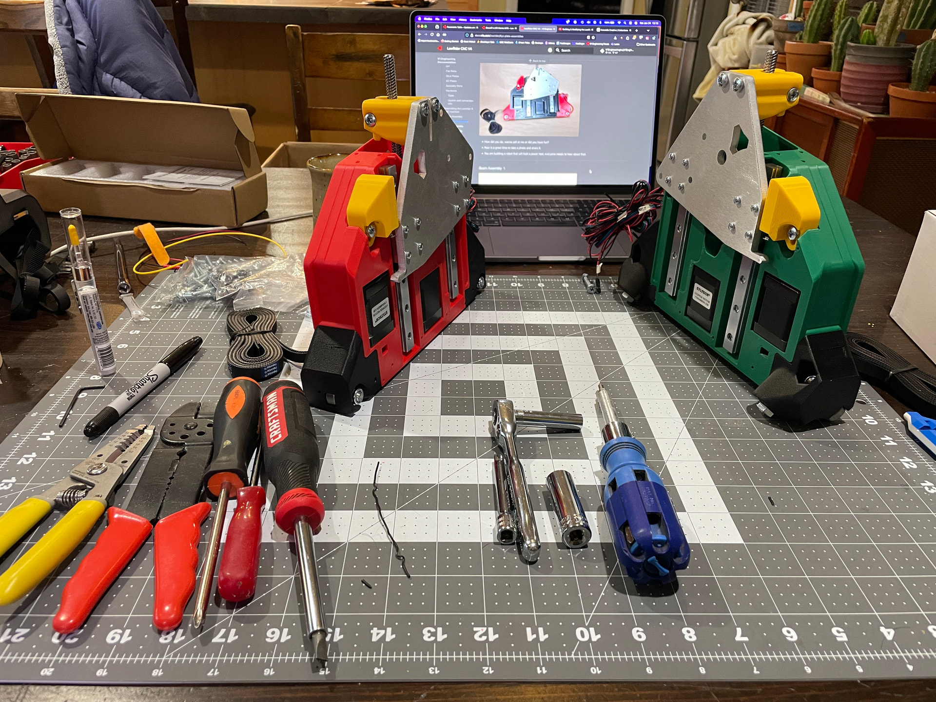
With Ryan’s detailed assembly instructions on the screen I gathered my tools and materials and posted up at the kitchen counter to start building (since it was freezing outside in the shop). As usual, I under estimated the time it would take to finish this part of the project (if my lovely wife ever read this post she would be rolling her eyes). The next morning I moved the project over to the dining table as I couldn’t continue to monopolize the kitchen counter without risk of upsetting my spousal unit.

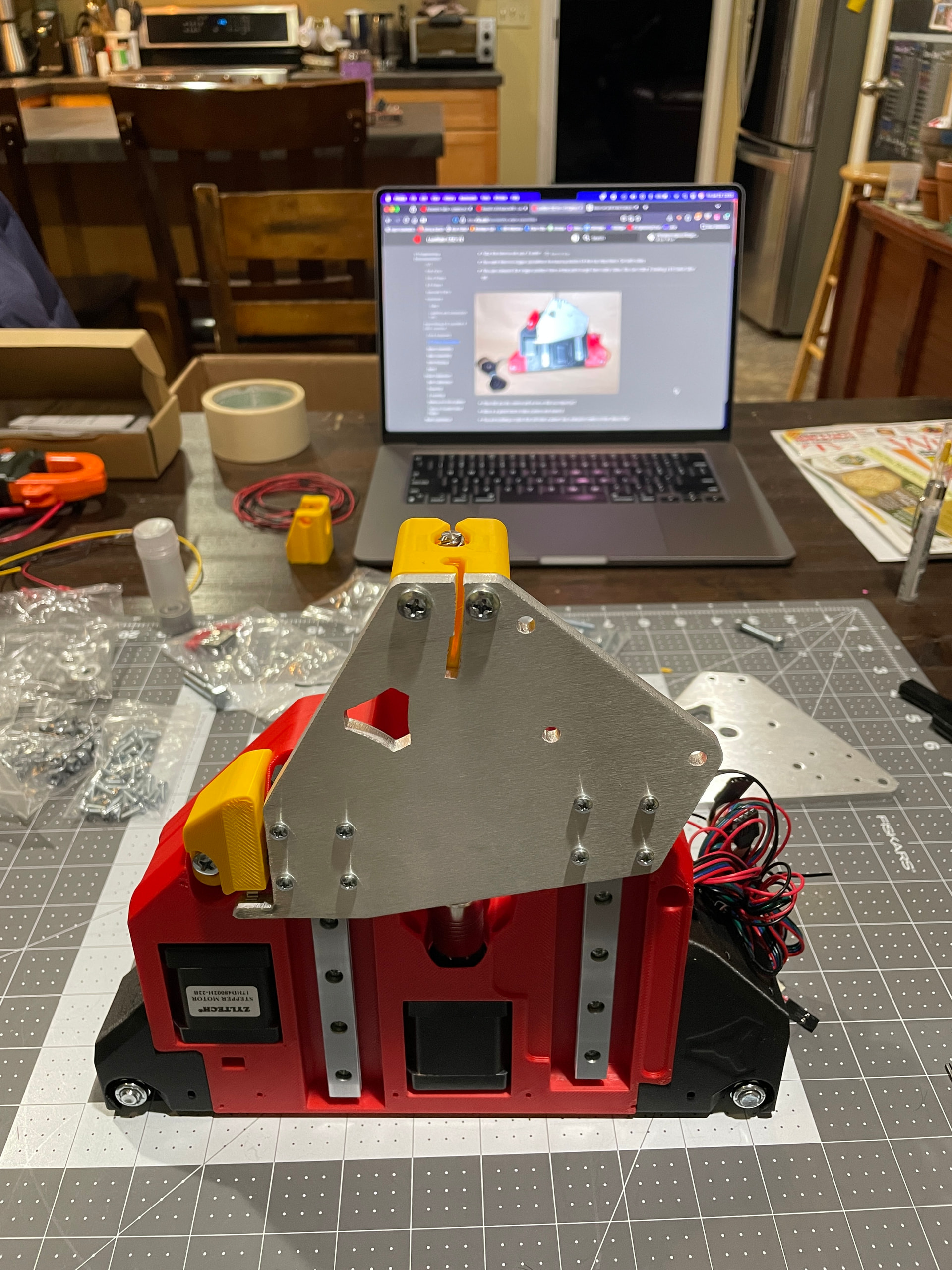
After a few evenings at the dining table, I was able to get most of the parts assembled in the warm comfort of the house before moving back out to the cold shop.

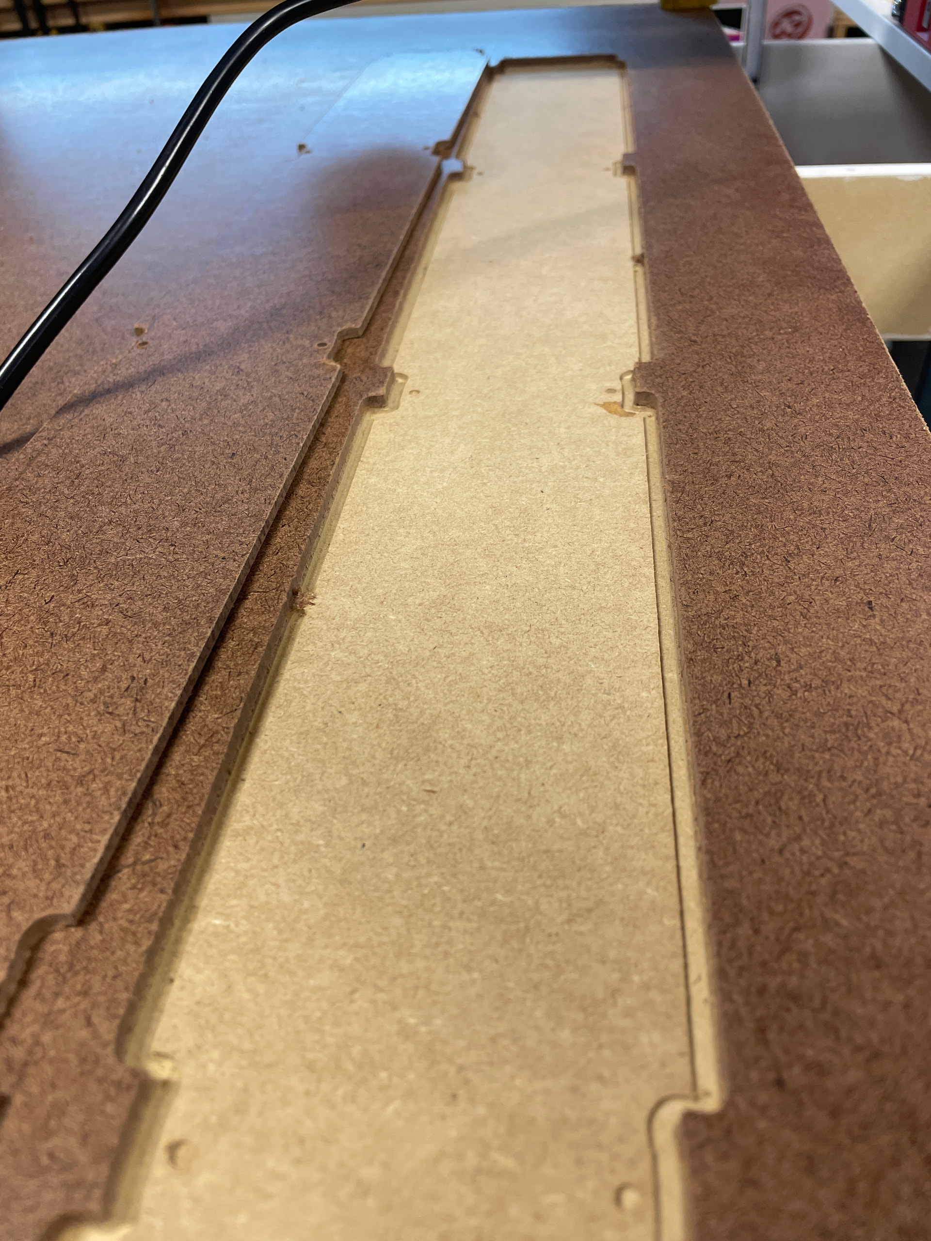
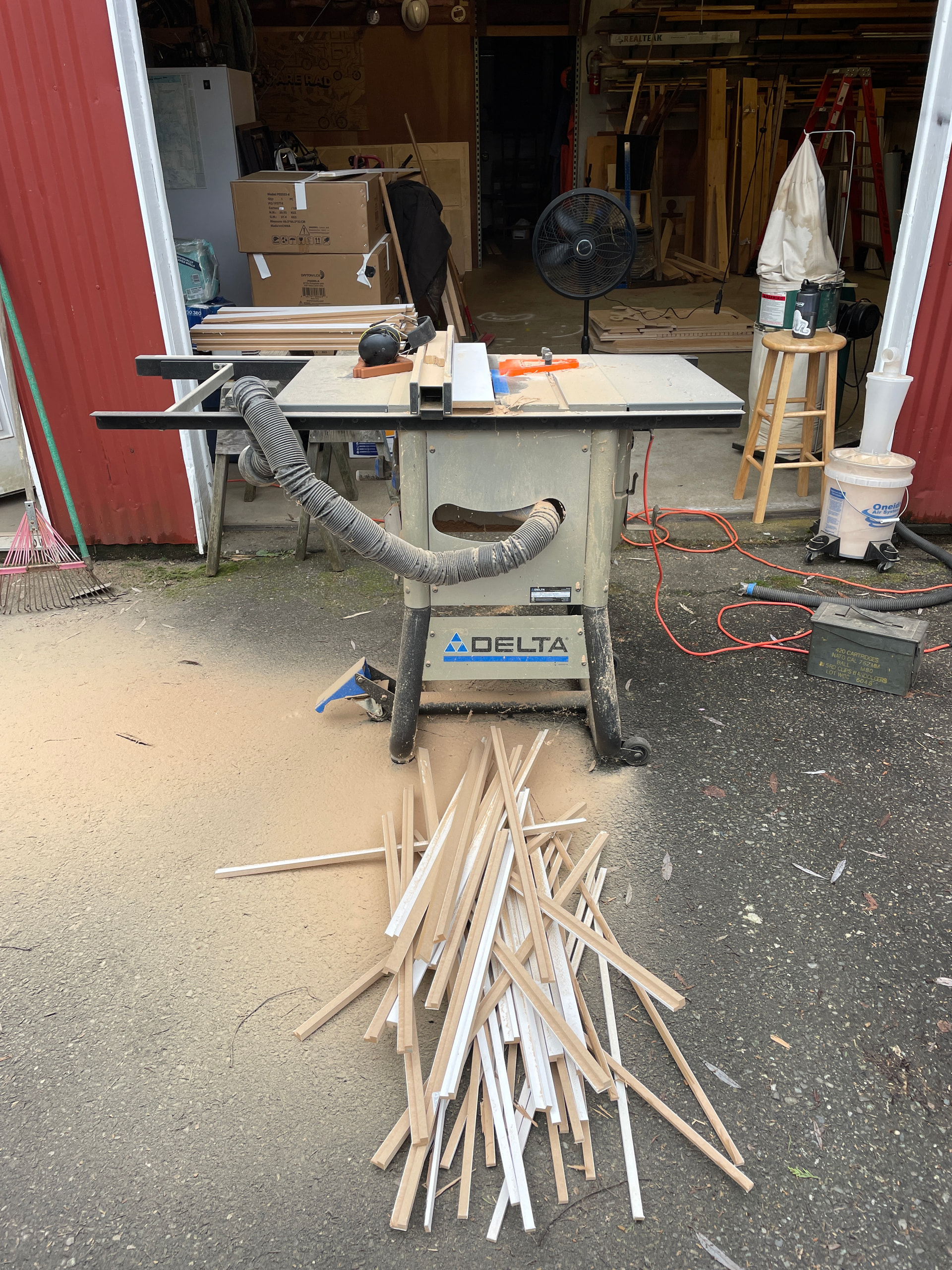
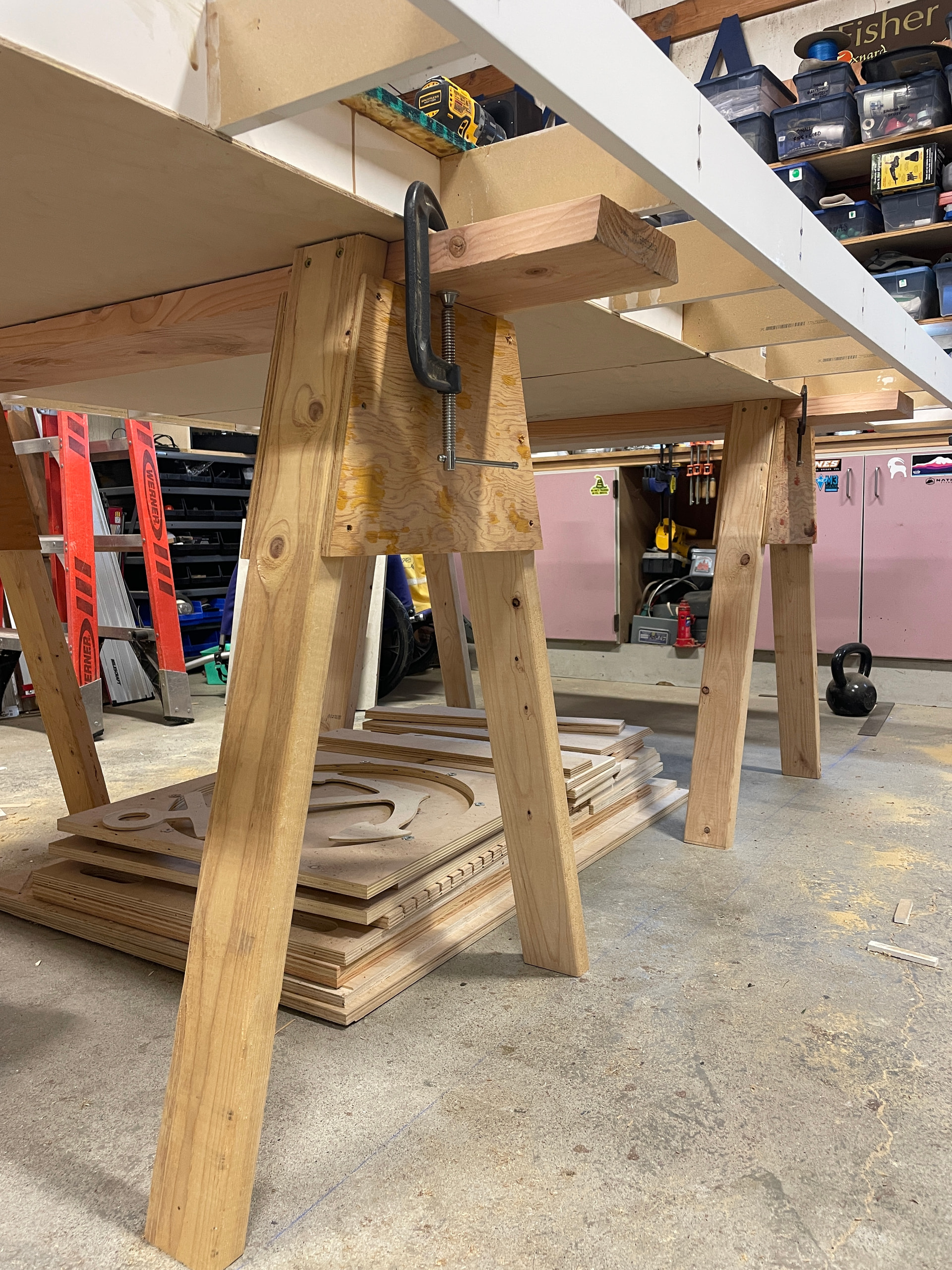
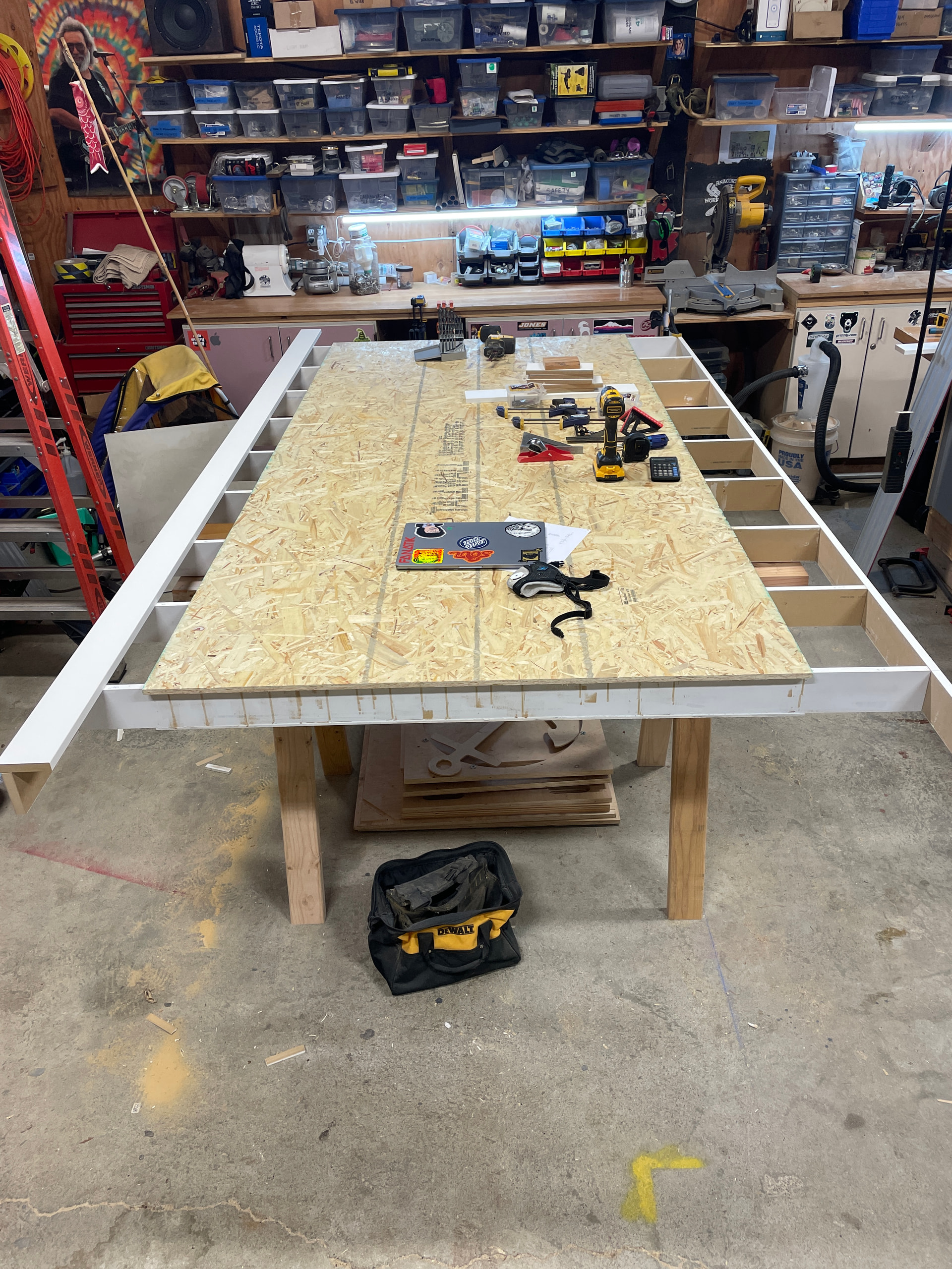
As a hobby woodworker for over fifteen years, I thought that building the table would be the easy part. At first I couldn’t decide on which table I wanted to build and spent way too much time researching the very impressive (but much more complex) folding tables and similar creations shared by very skilled people here on the forums. Once I abandoned plans to build a complex table and decided to go with the table Ryan and others recommend, I still wasted too much time trying to “re-invent the wheel” by coming up with unnecessarily complicated jigs and other distractions. In the end I built a sturdy torsion-box style table using MDF boards with OSB top and saw horse legs, and I’m happy with the result even though there are many imperfections that only I know about and will never speak of publicly. :shushing_face:

After a few late nights freezing out in the shop I realized that I was suffering from what I call the three too’s (3-2’s) problem. That is: too late, too tired, too many beers. My wife would say that I tend to be a perfectionist, and working late in the shop when I’m tired and had a few beers doesn’t contribute to my best work. Like all good woodworkers I know how to hide my flaws well, and thankfully the end result is within acceptable tolerances.

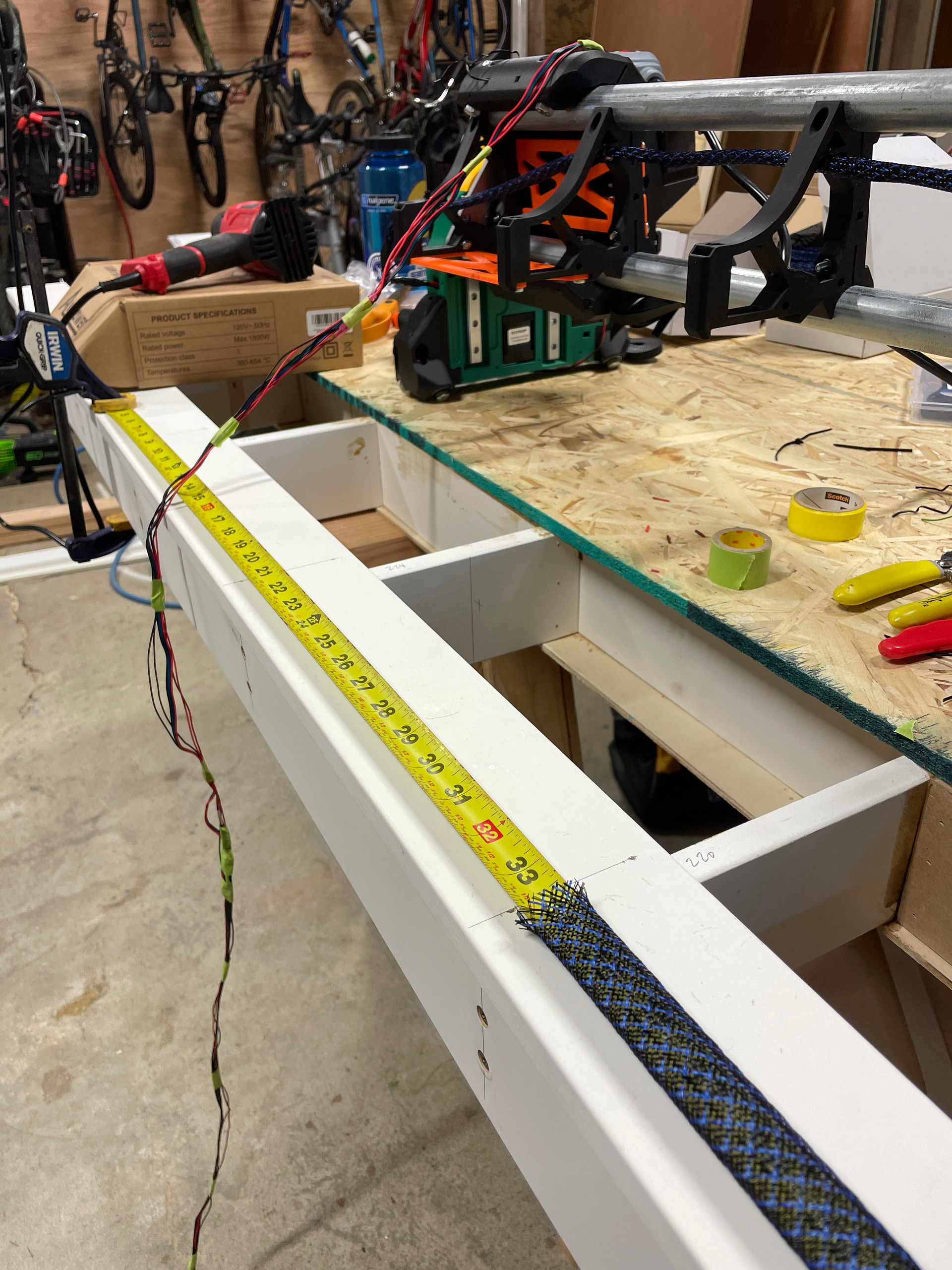
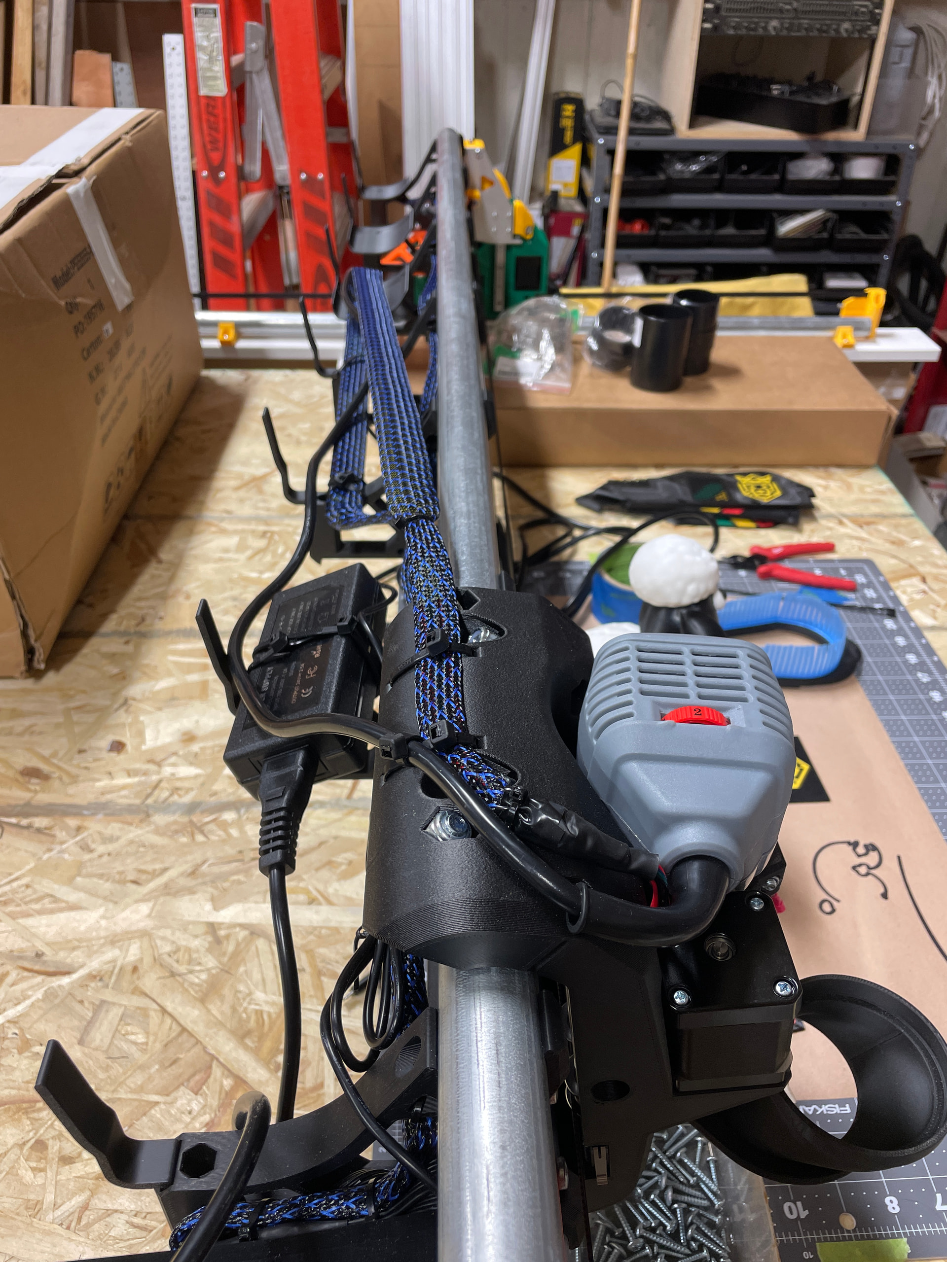
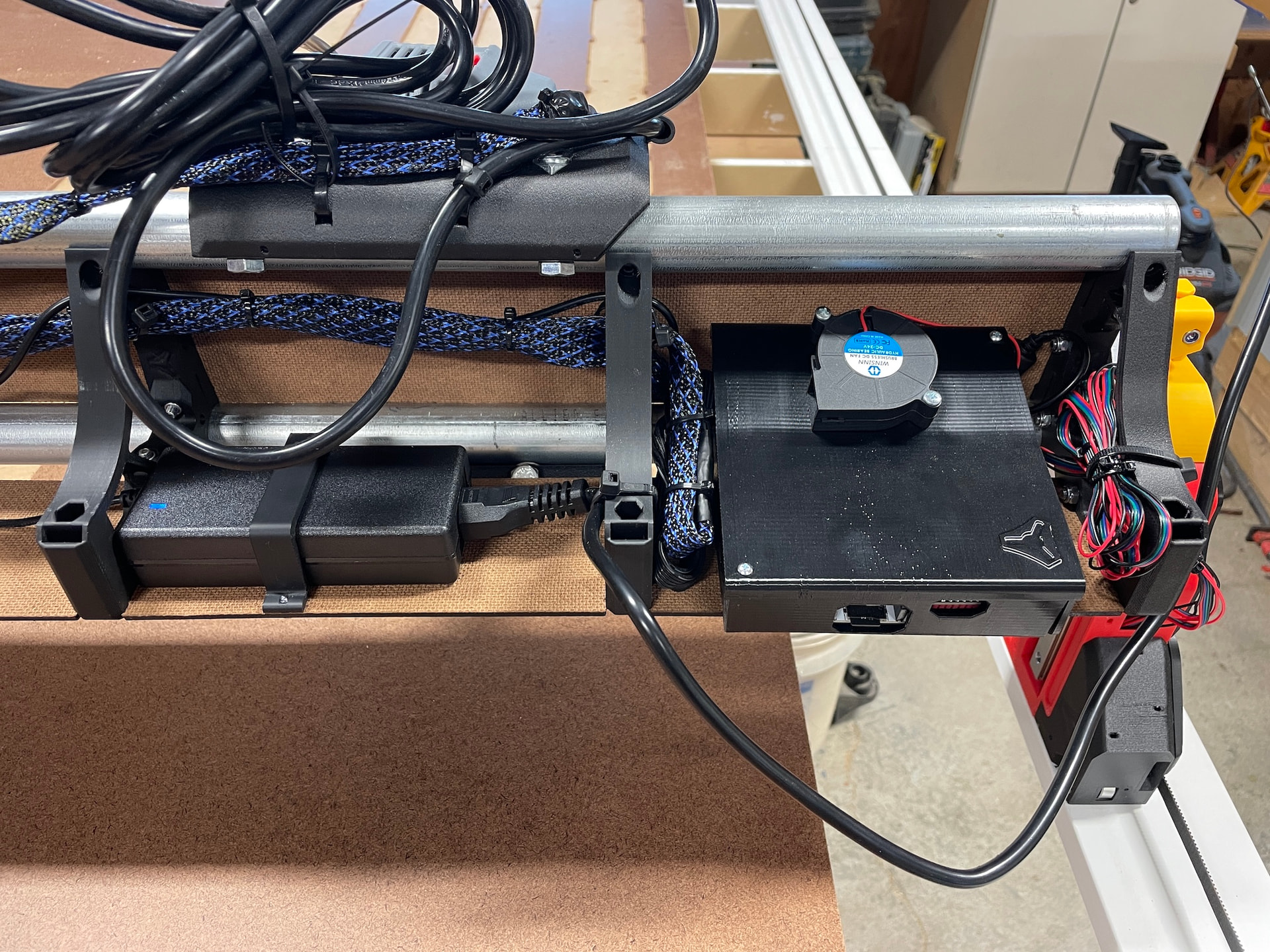
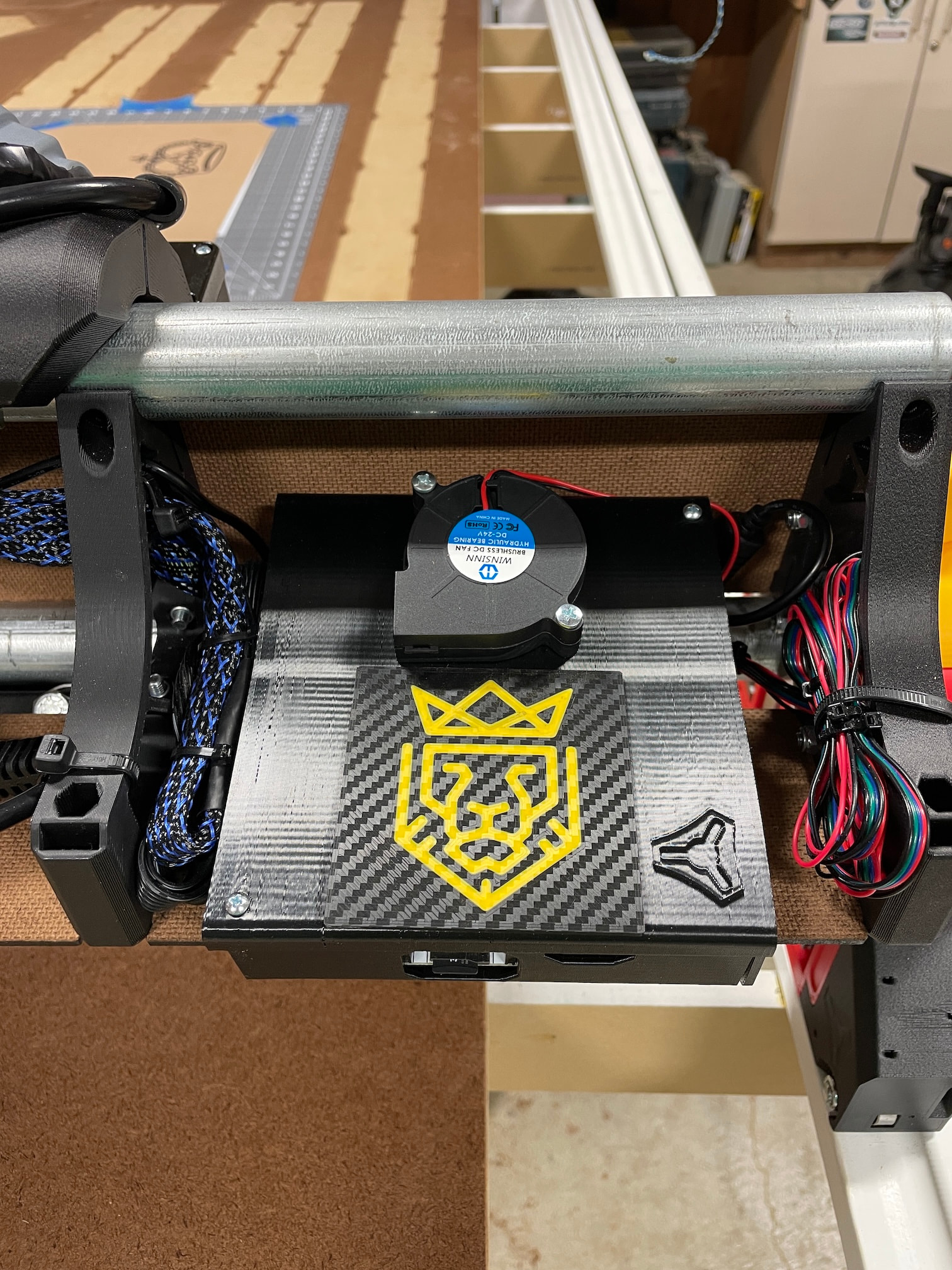
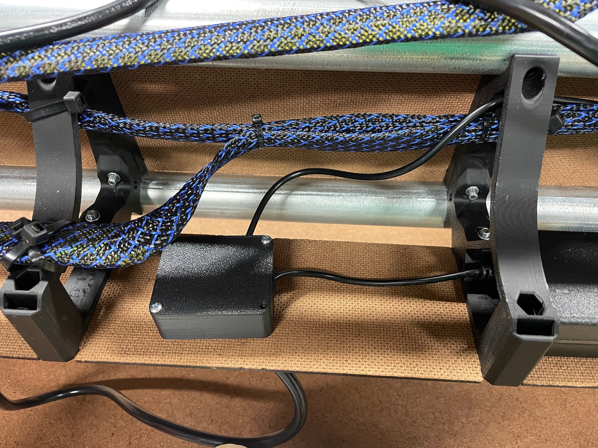
I decided on the “tape measure trick” for cable management. This was my first time using PET sleeve in a project and there are a few places where I could have done better, but generally I’m happy with the results.

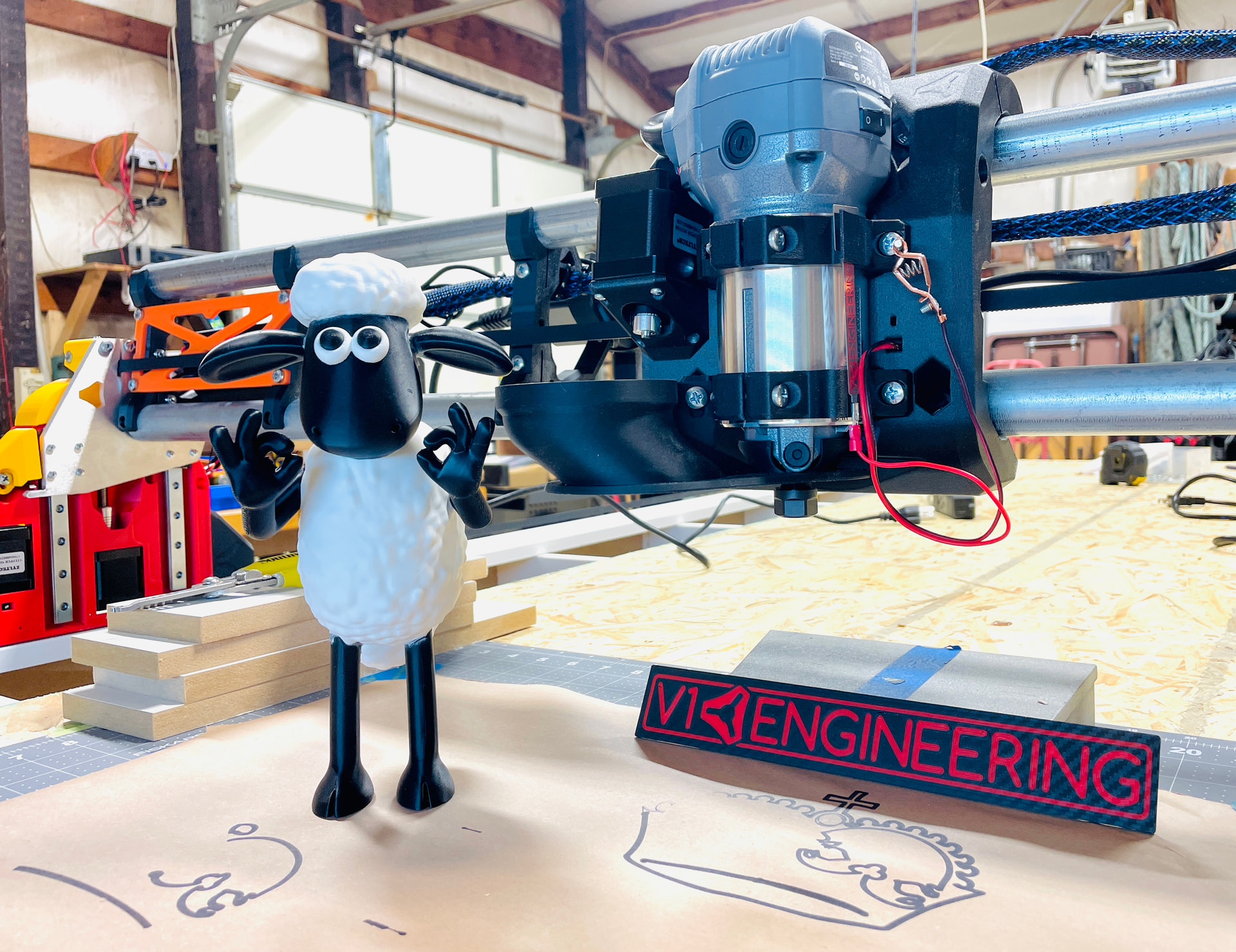
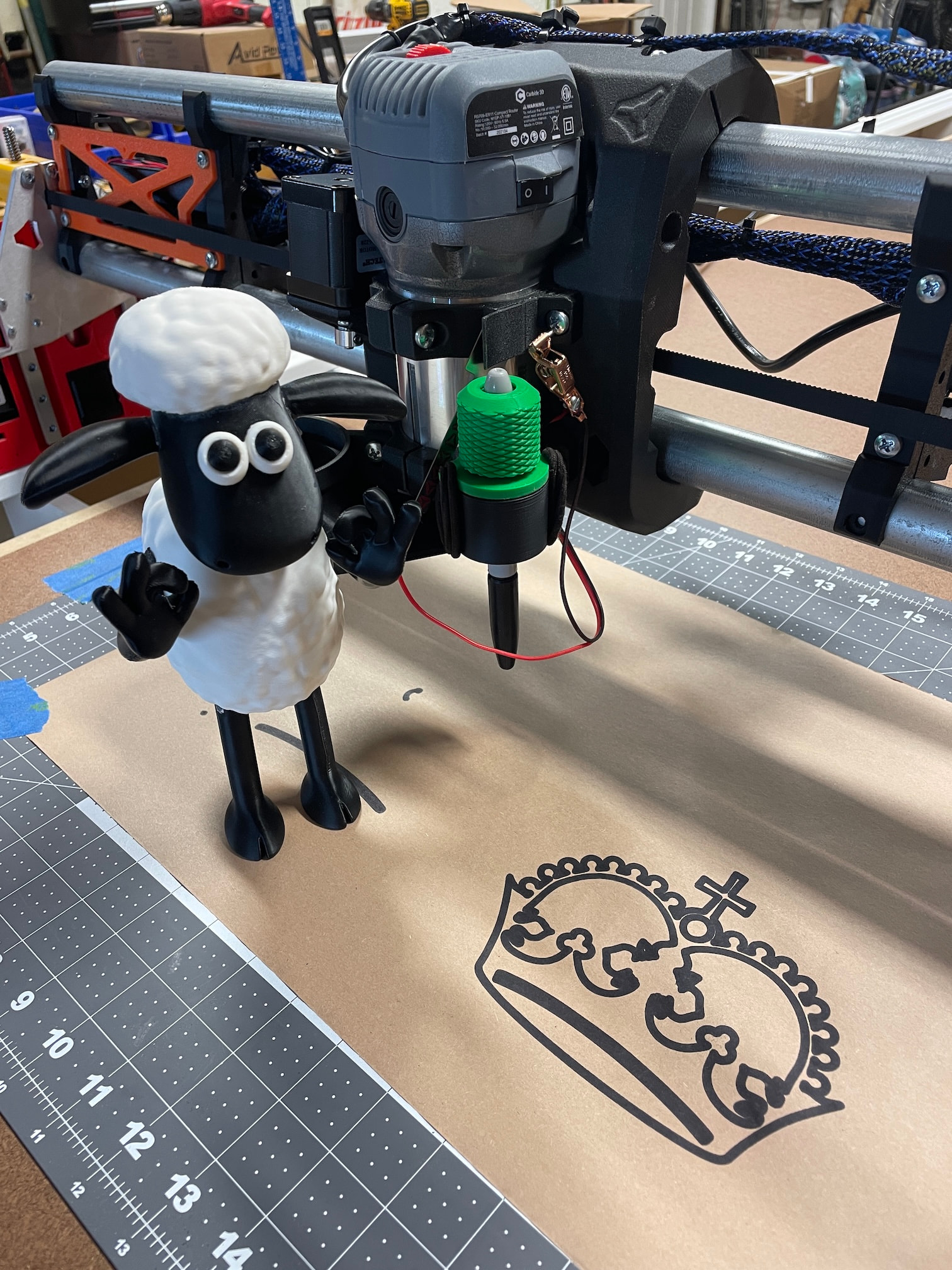
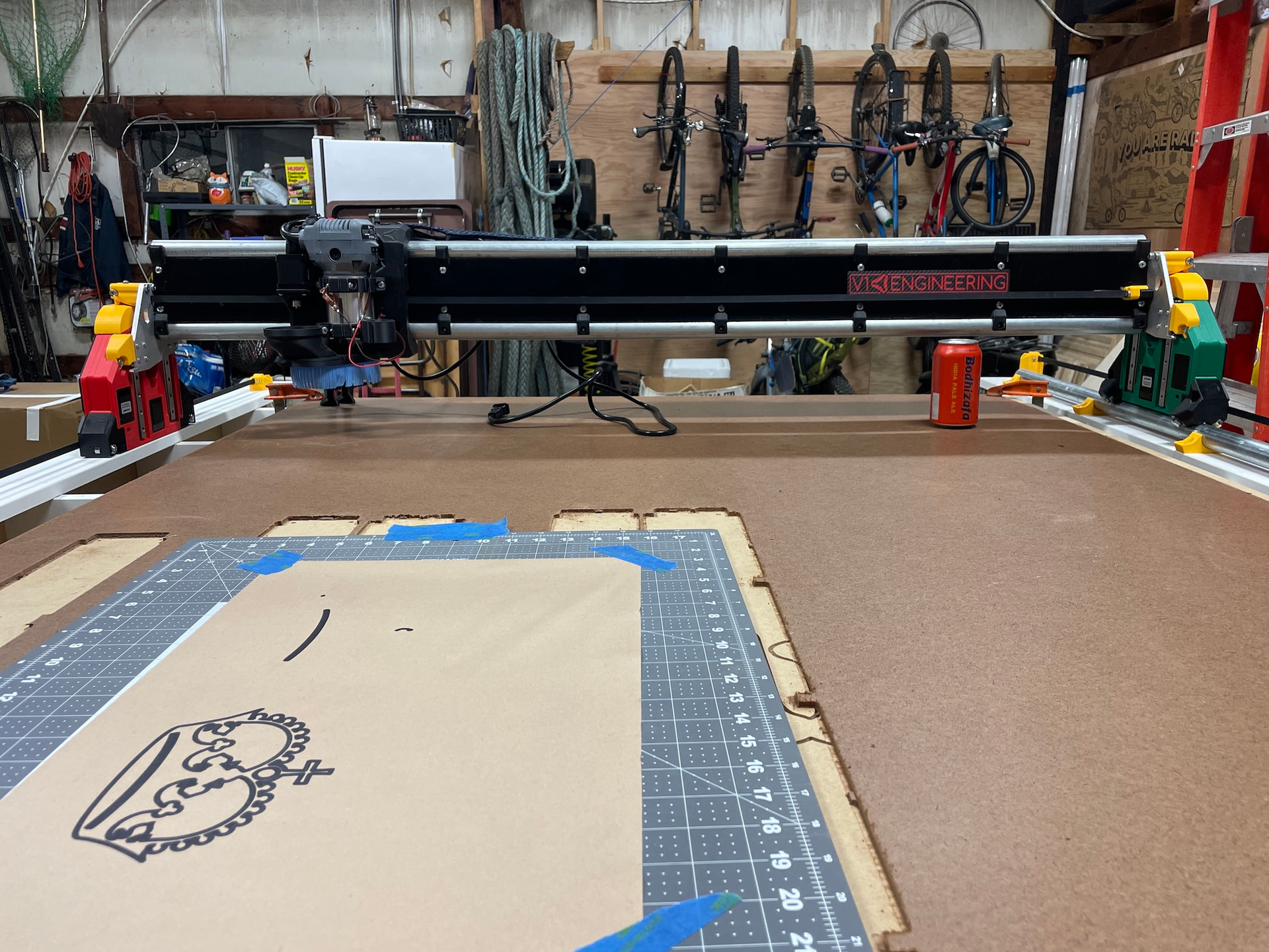
Final assembly went smoothly and I was thrilled to power the machine up, connect via AP and jog the thing around the table. Of course I couldn’t wait to see it draw something…so I skipped ahead a few steps and tried to draw the crown with a sharpie haphazardly taped to the core. It only got most of the way through before the pen fell off, but I was thrilled that this beautiful creation was working! It was time to square and calibrate while I printed a proper pen holder for the accessory mount.

I’ve got more to share…to be continued…

10 Likes

After my failed attempt at drawing the crown using a pen taped to the router, I did a search on Maker World and found an impressive looking pen holder made to mount to the LR4 core. I later discovered that the pen holder was designed by a skilled maker here on the forums: @CABix…thanks for sharing your design Craig!

Note: I was also impressed with this print of Shawn the Sheep from user @ModelLover on Maker World and decided he would be the unofficial mascot for my build. I completed most of this project working solo and needed someone in the shop to share my excitement as things came together…Shawn was always enthusiastic about my progress!

Craig’s pen holder attachment worked perfectly and I was able to complete the crown! The pen holder also works with the blue “contractor” pencils from Lowes and is a great addition to the LR4. Before attempting to cut the strut plates, I first ran the file using a pencil just to confirm that the size from the strut plate generator was going to work with my finished gantry and that the machine wasn’t going to do something unexpected.


At this point it was starting to get late (3-2’s problem) and I didn’t want to rush anything with the strut plates but really wanted to have something to show the family in the morning so I made a quick sign using an old file I had on the computer (Odin is our son’s name). Taped a piece of scrap to the table and cut using 2-flute 1/8” down-cut mill with 2mm DOC and 700mm/min feed rate. I screwed up the tabs when making the toolpaths in CAM, but otherwise I was thrilled with the first cut from my new LR4!

The next morning after calibrating and squaring the machine I cut the strut plates. First one was a test to check size and see how the machine did with this new material. Then I cut a pair plates only to discover that the toolpaths needed some tweaking. After more testing and adjustment I cut the final two plates which looked like they would work.


Here you can see my first three test strut plates, and the final two in the middle which were installed on the machine. You can also see various test cuts I used to adjust toolpath settings and verify accuracy of my cuts. I can’t find any photos of the machine partially disassembled to install the strut plates, but I tried to follow the yellow brick road and was able to install the plates without too much trouble. I was really nervous about this step because I had a working machine that was making cuts and I didn’t want to take it apart for fear that I would screw something up in the process. I detached the green YZ assembly from the gantry because I needed to snug the linear rails and bearings on that side, but then realized that I wouldn’t be able to take the core off on that side. Not wanting to detach both YZ assemblies, I was able to get the strut plates installed by moving the core all the way over to the X-min side and with some help from an assistant shimmy the front strut plate under the core and into position. More updates to follow…

4 Likes

What a fantastic build, and a great start for a build thread.
Aside the machine build, please share more of your speaker box and rack box builds.

1 Like

What a perfect first post!!! I love the build, I love the attitude, and I think I need 3-2’s sign.

1 Like

That’s a magic phrase right there!

As I mentioned before I didn’t get any photos of the machine disassembled during installation of the strut plates…I was a little nervous about taking it apart and focused on trying to get it back together before my helper had to go. Here’s a little video of the LR4 cutting a test shape out after getting everything put back together:

Test cut after strut plate installation

The increased rigidity with full strut plates is impressive, and I look forward to seeing what it can do after I get when it all dialed in.

The control box was printed using PC-FR filament from Babmu Labs. Not required obviously, but I wanted to experiment with some of the “engineering” filaments Babmu offers. Most of the parts were printed using standard PLA. The core, min/max “wheel” and end braces were printed using Bambu PET-CF, which is probably my favorite filament that I’ve tried so far.

I wasn’t sure where I was supposed to put the fan, so I ended up mounting it on top of the control box. Seemed to make the most sense to me…pulling the warm air out and exhausting it? I couldn’t find many photos of control boxes with fans in the build threads, but it seems like at least a couple of people have done it this way. I was concerned that if the fan blew air inside the box it would just coat everything inside with a layer of dust. :man_shrugging:

I designed and printed a little strap for the 24v power supply…if anyone is interested I can post the model on MW.

I also printed this little j-box for a pair of WAGO connectors, there are many good options for these on Maker World. Currently it is only connected to the Jackpot board and fan, but I have empty terminals for future LED lighting under the gantry.

That’s about it for the build so far. Still need to tidy up some of the wiring and add more protective sleeving. Also plan on adding e-stop(s) and want to figure out how to control the router power using a relay as others have done.

Perhaps the most important task remaining is to figure out a better solution for dust collection. Right now I have the hose running to a bucket cyclone separator and then going to my little shop vac. I do have a bigger Grizzly dust collector in the shop, but it needs to be plumbed with some hard pipe and blast gates. Also looking for recommendations on the best dust collection hose to use. I picked up an inexpensive one from Grizzly, but it is just too stiff and I couldn’t get it to work on the gantry so I ended up supporting it from above with some rope. I’d like to find a much softer hose, and maybe wrap it with PET sleeving so the ribs don’t get stuck on everything when the machine is moving around. If anyone has advice for dust hoses let me know!

Thanks again for the help and encouragement, happy to answer any questions anyone might have about this build. I’ll add to this thread as I continue to make improvements in my setup, and start new threads detailing the projects I’ll be working on. Cheers! :victory_hand:

5 Likes

You have your fan 100% correct! Good job!

1 Like

Perfect!

Heck yeah.

The one linked in the instructions should be super flexy.

2 Likes

Love the Shaun the Sheep figure!

2 Likes

Thanks so, so much for the call out. On this group I feel so many others are such heavy lifters glad I can help somehow​:+1:
Nice build and fun!!!

4 Likes