The long story short of my first MPCNC

'Ola, my name is Linda and this is my MPCNC story.

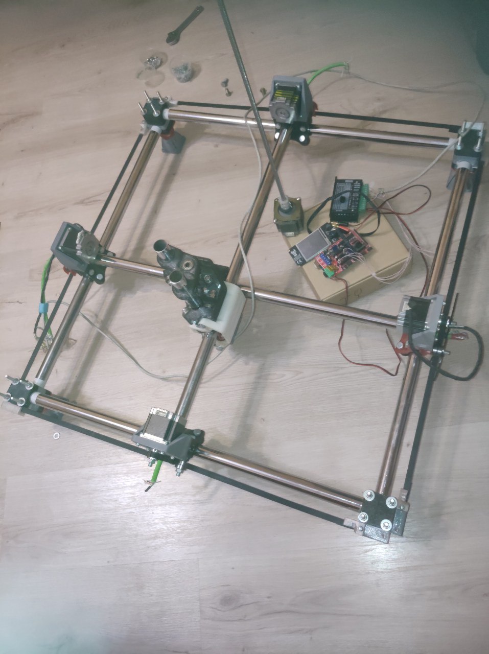
It begins around 2018 when I was posessed by a dream of a true DIY REPRAP CNC and found a Vicious1 and MPCNC and the work begins :smiley:


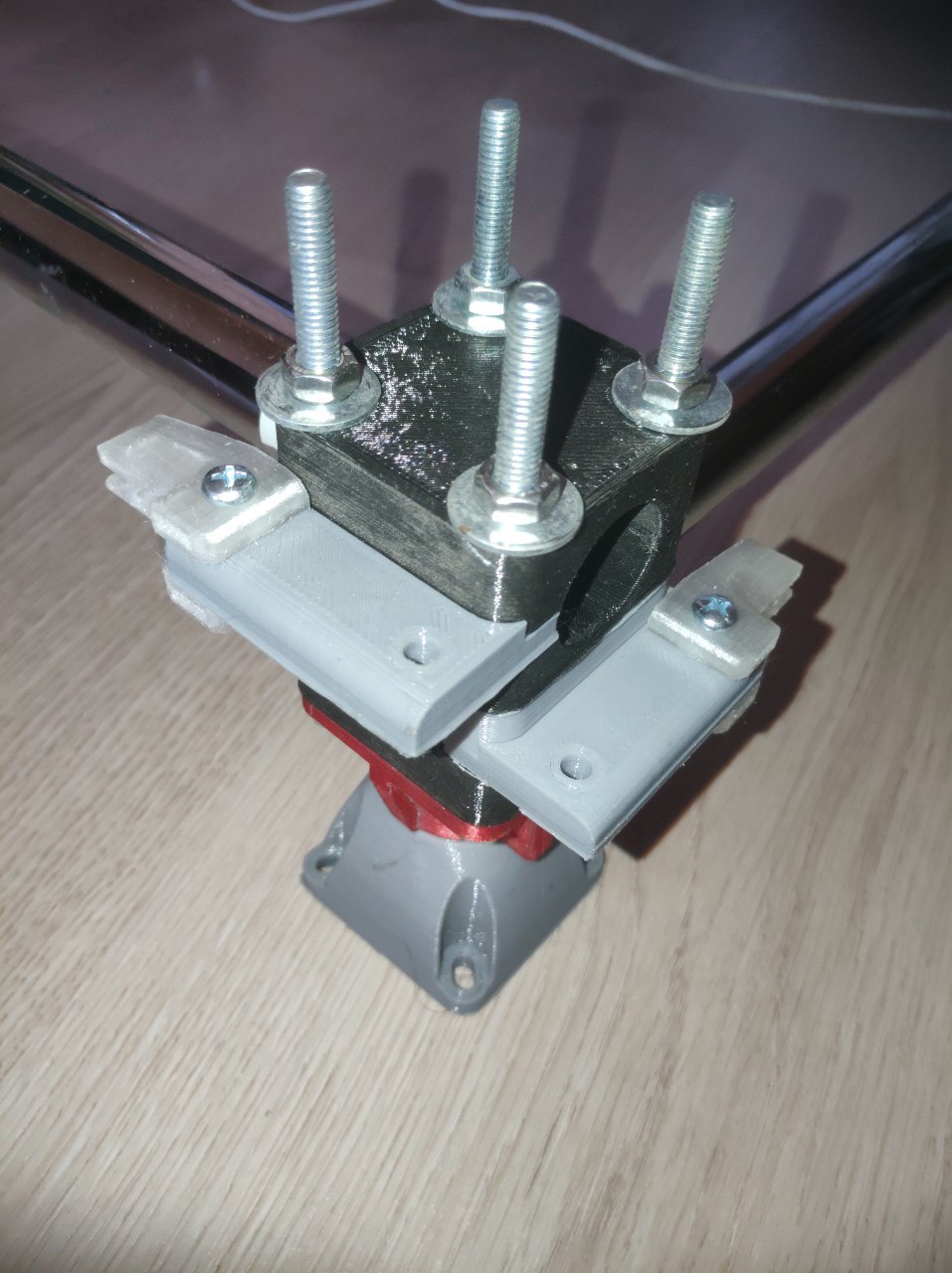
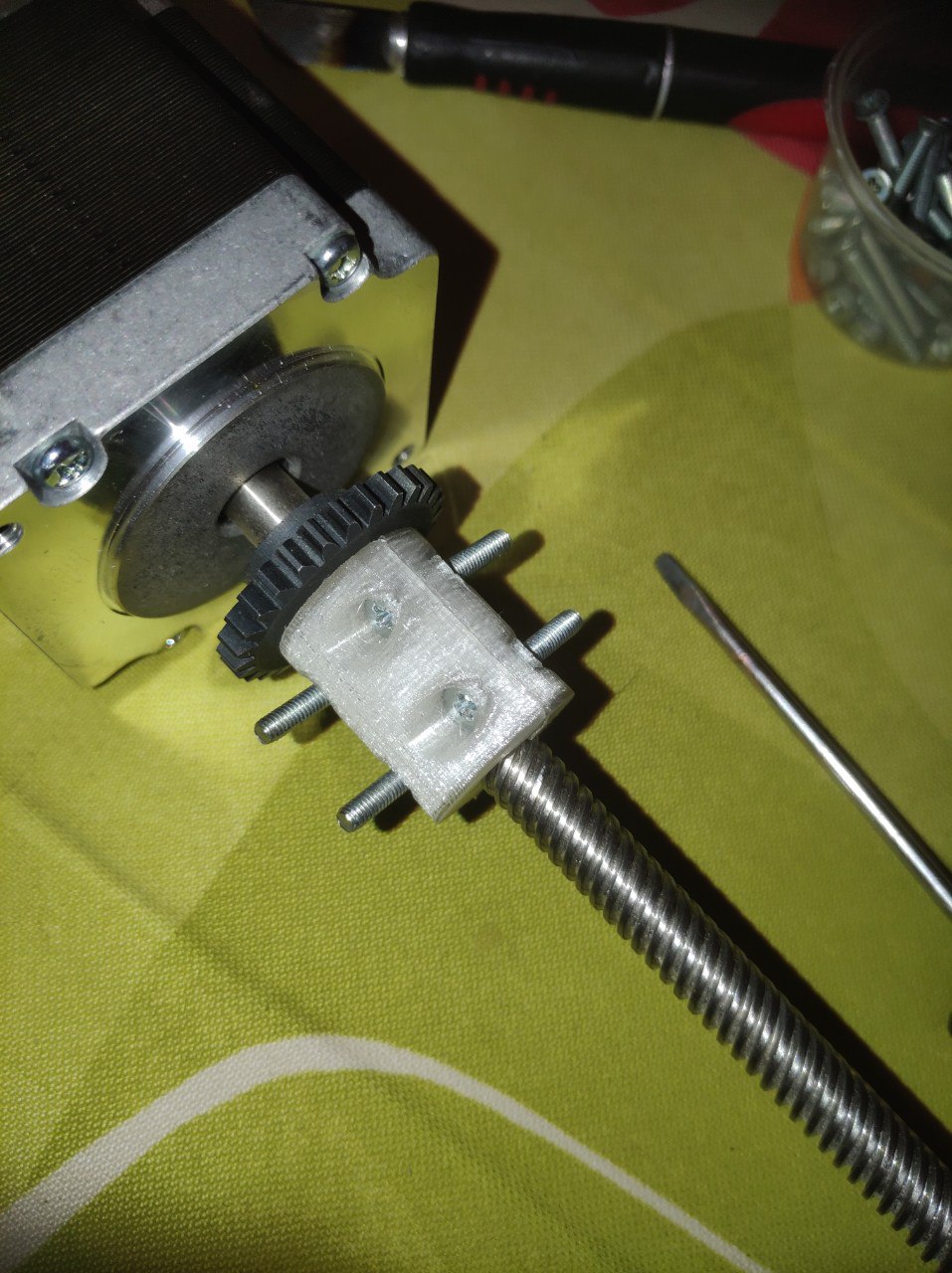
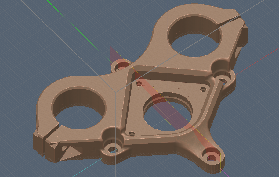
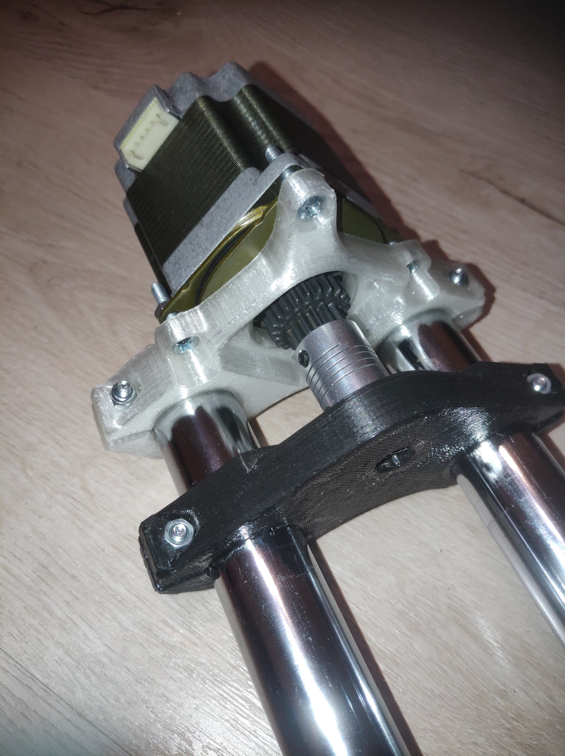
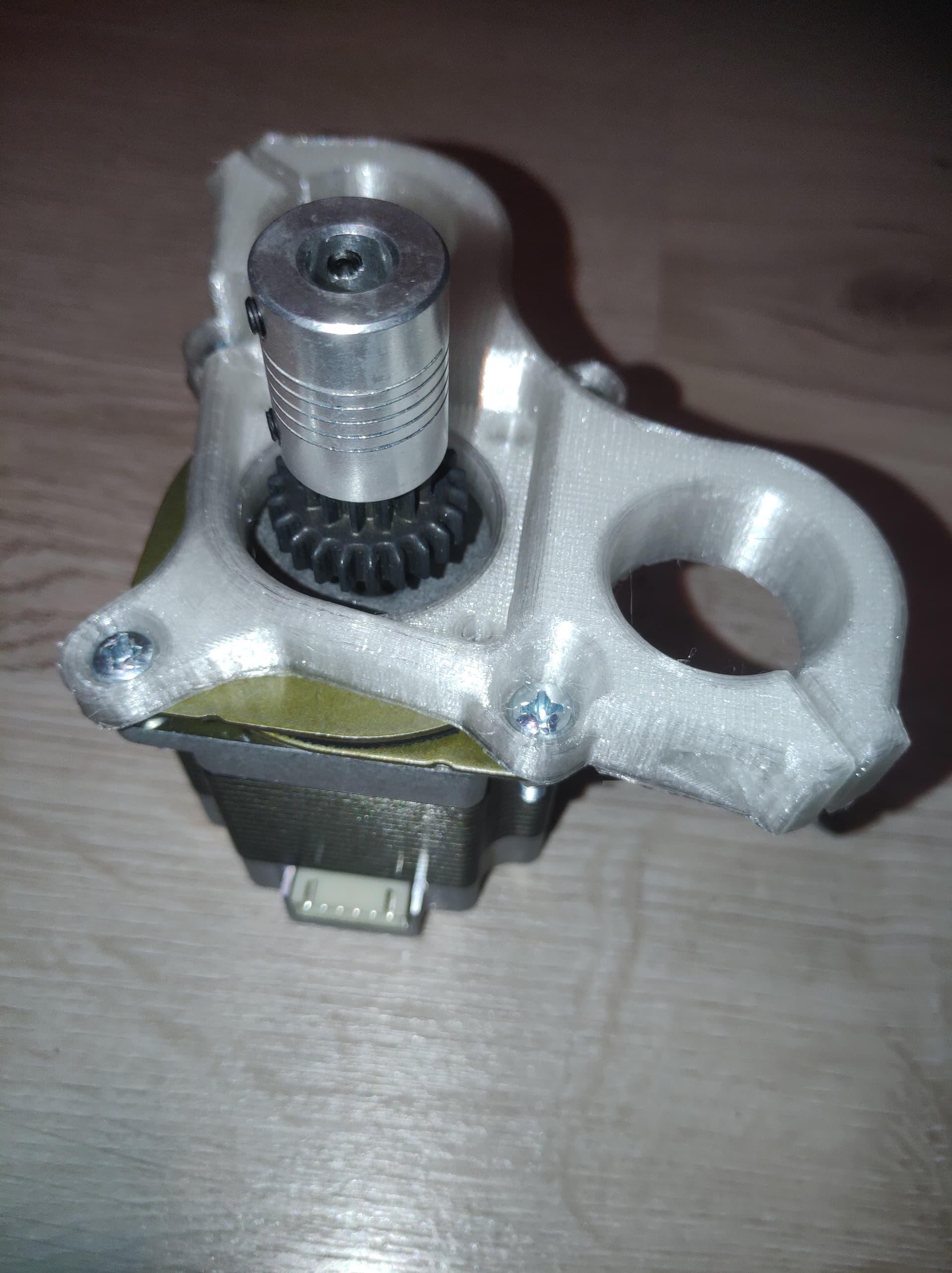
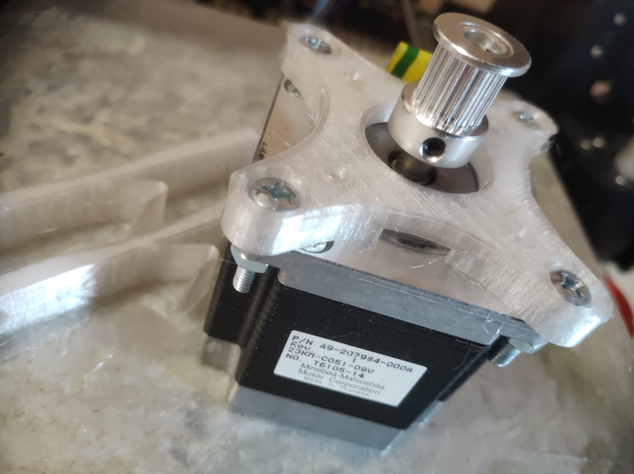
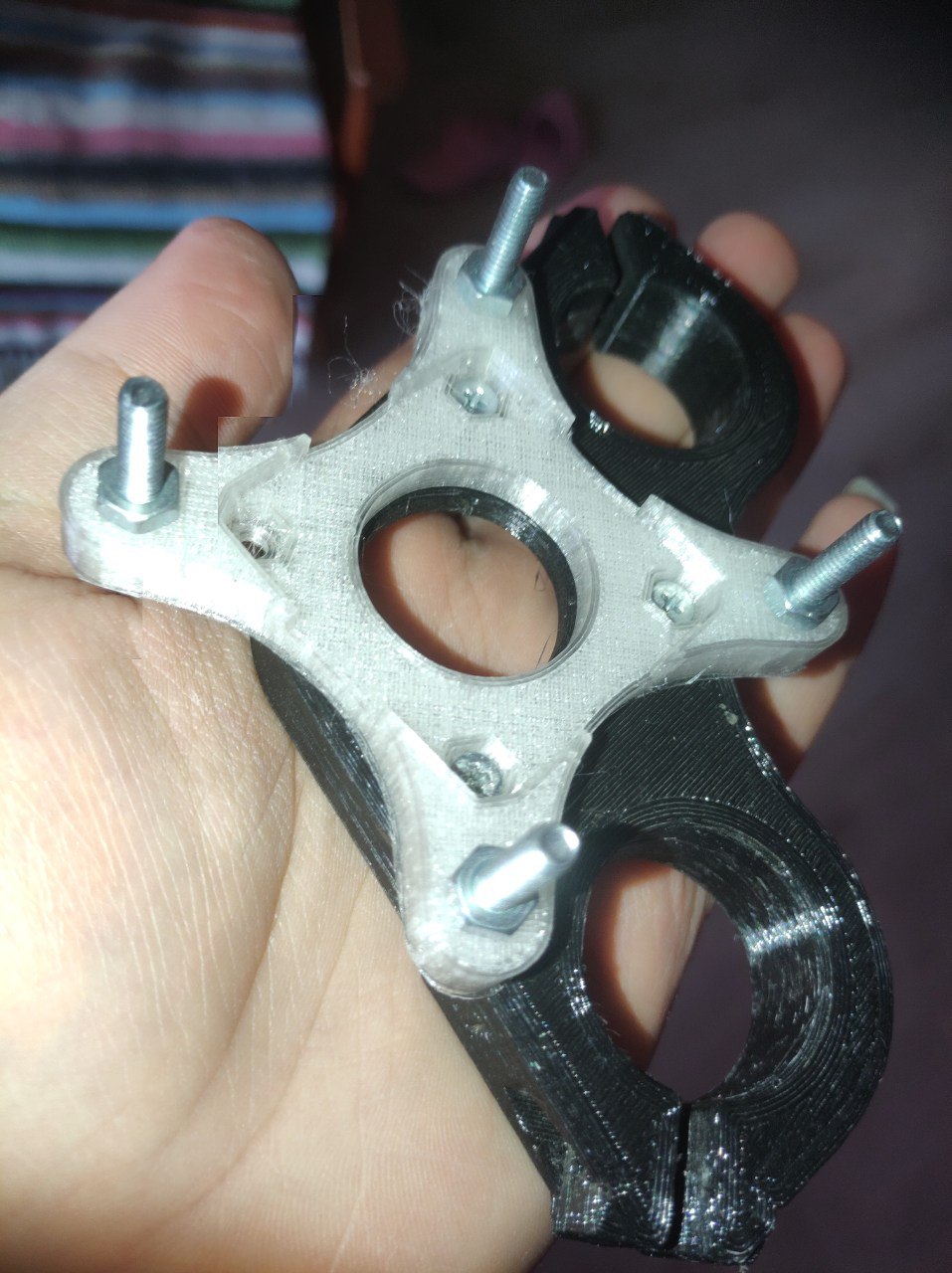
At first the idea was to use a nema23 instead of nema17 and i made my own nema23 motor holder:


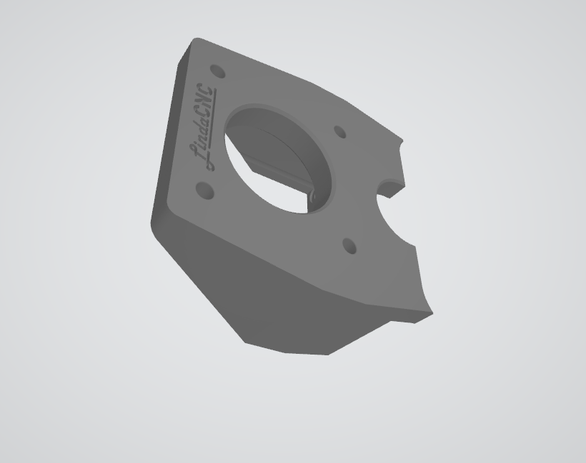
Btw if someone looking for my nema23 holder mod: here it is

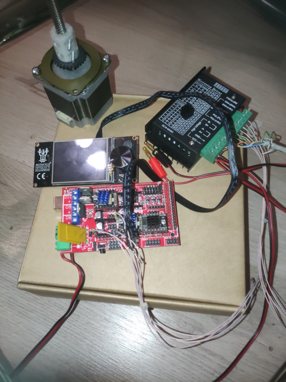
After that the madness threw me forward to the experimenting and testing how to control the motor and so on:

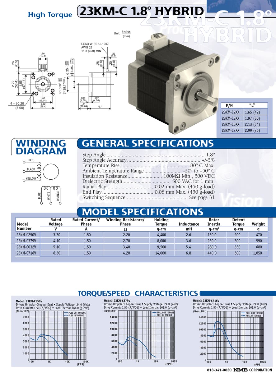
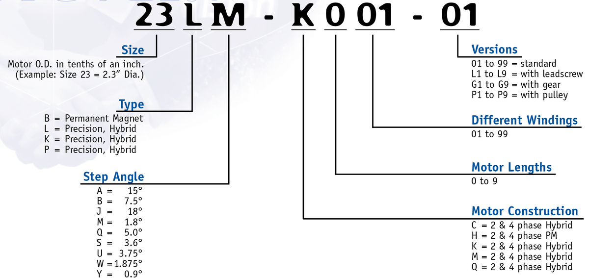
Nema23 ( 23KM-C051-09V ) test on Ramps 1.4/TB6600 driver

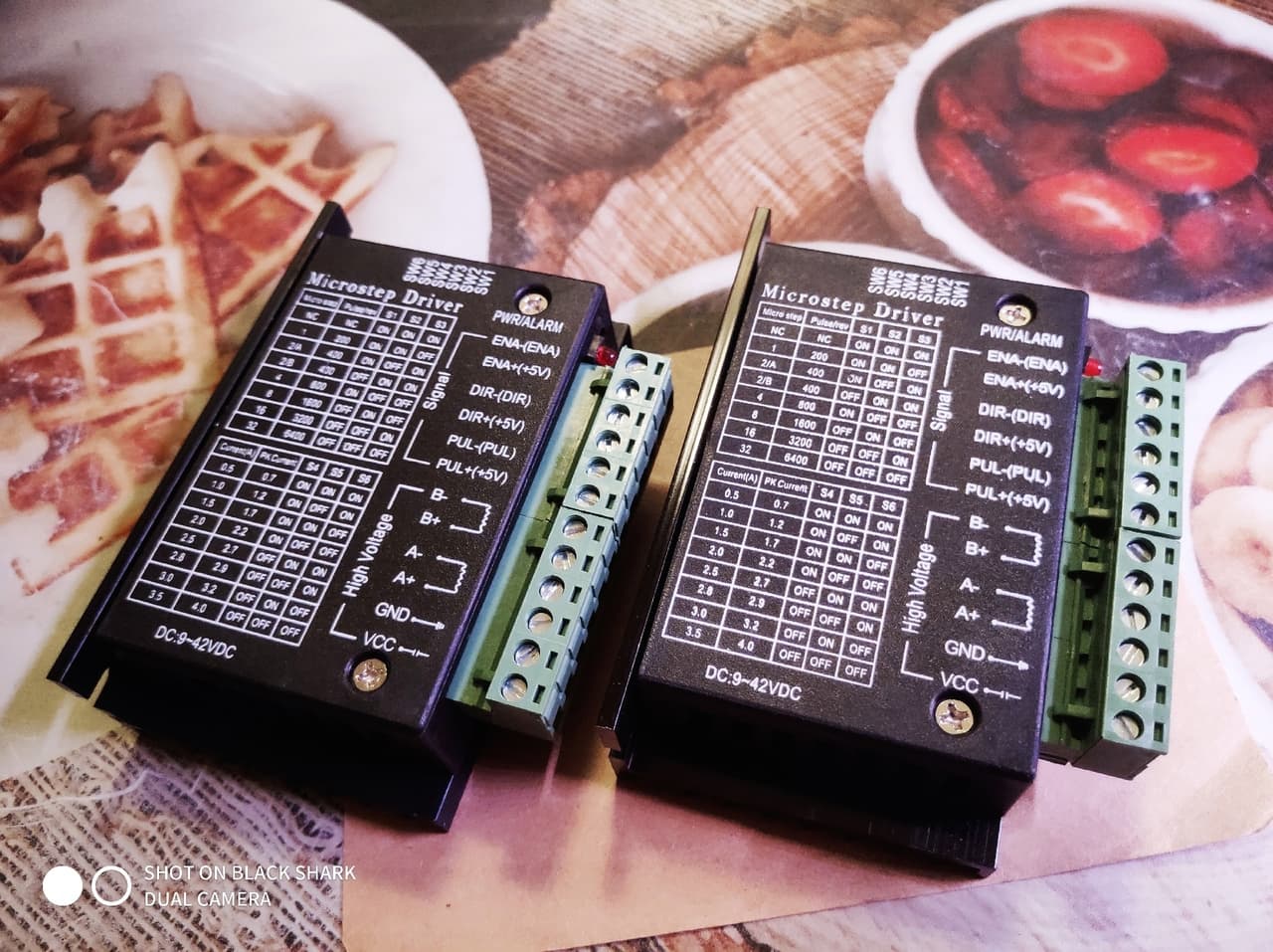
And and I trapped around way to use TMC2208 or TB6600. And left the TB6600 as working version.
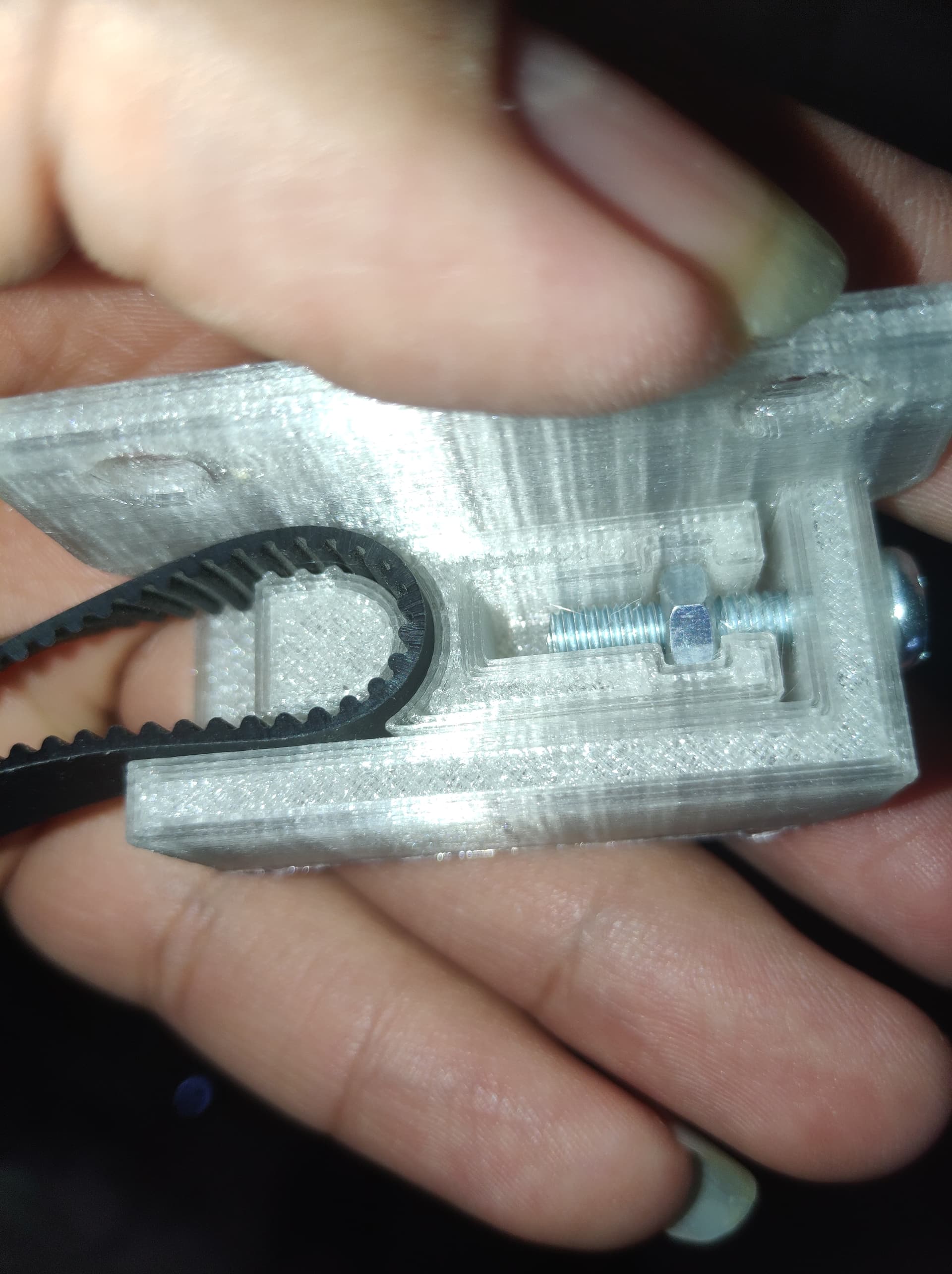
Than was a battle to control 2 motors via one driver:

After some results I focused to use 1 motor per one driver instead of 2per1.

Than becomes the EXperiments. I has an idea to use a chains instead of belts… why not? I made a prototype:


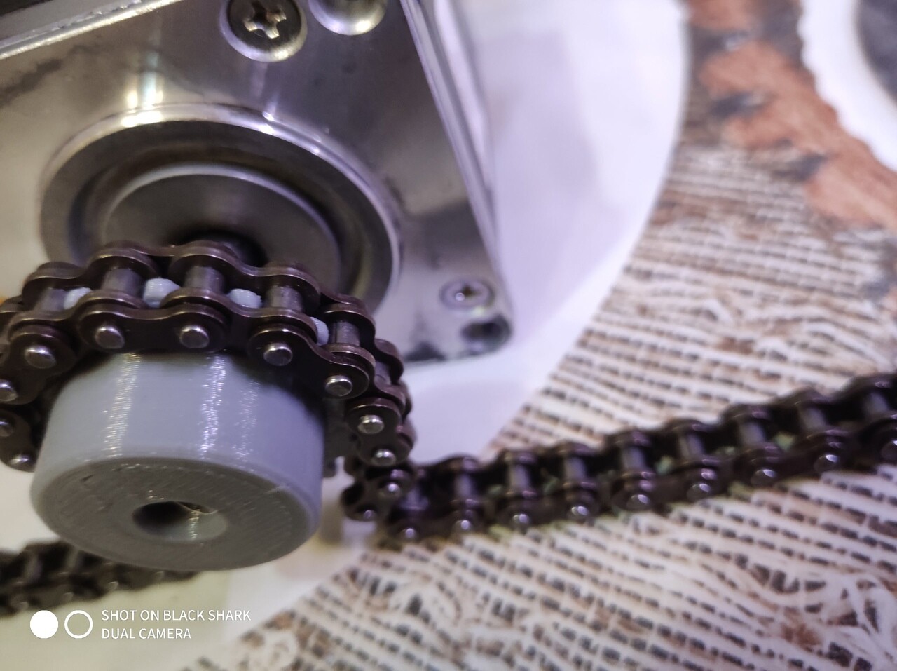
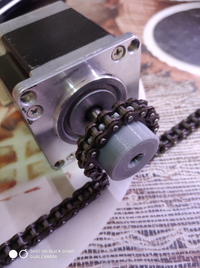
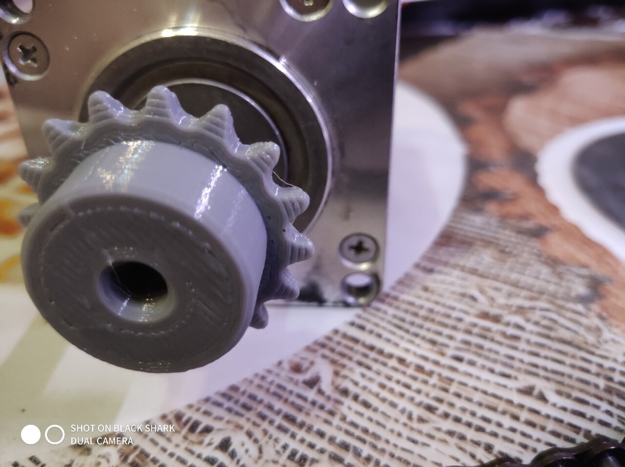
It was funny i can say:

But in some case im back to the belt version and left the chain to the history for no reason mb become bored XD And may be some day i will make a chain-based version too…

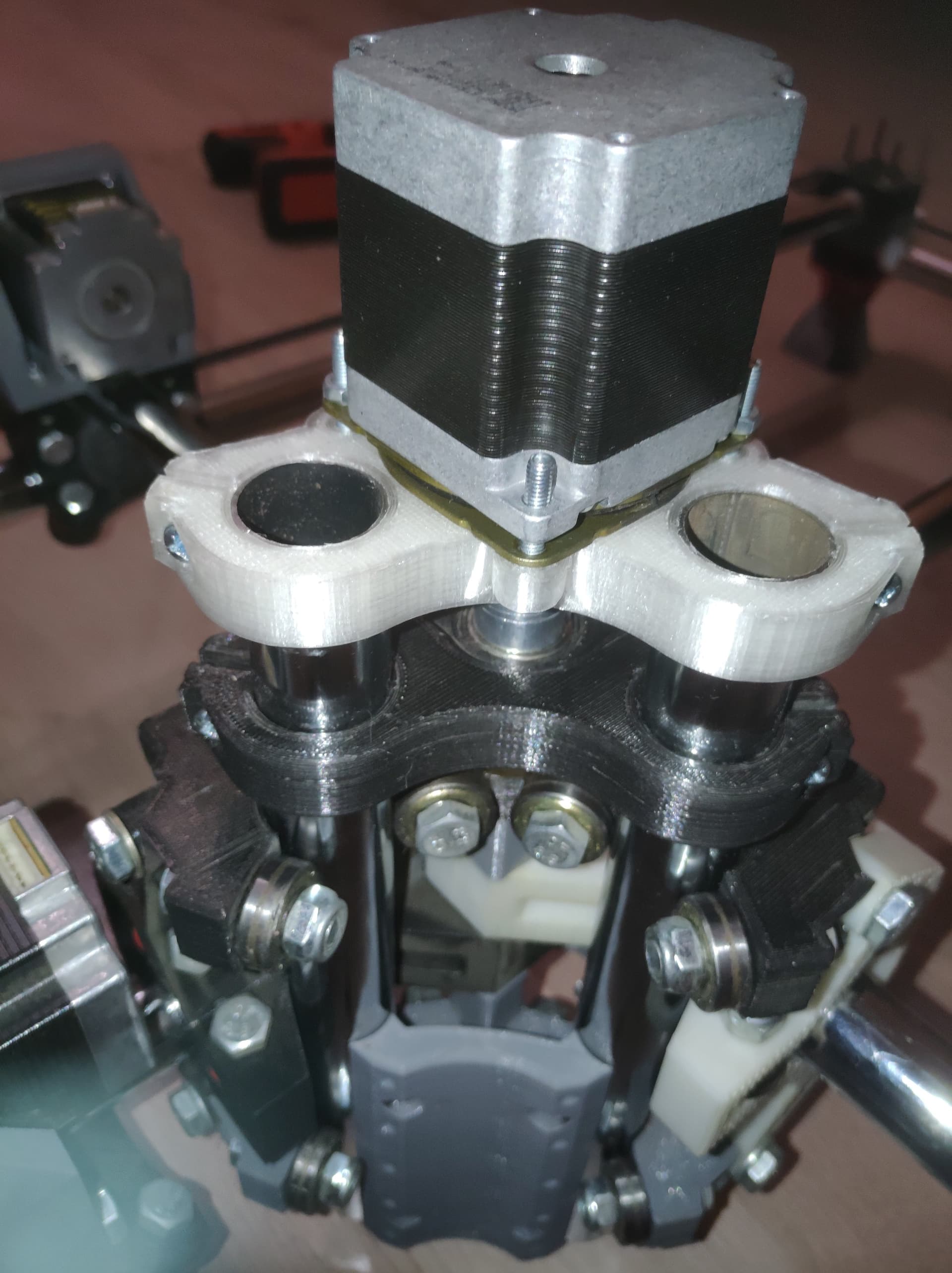
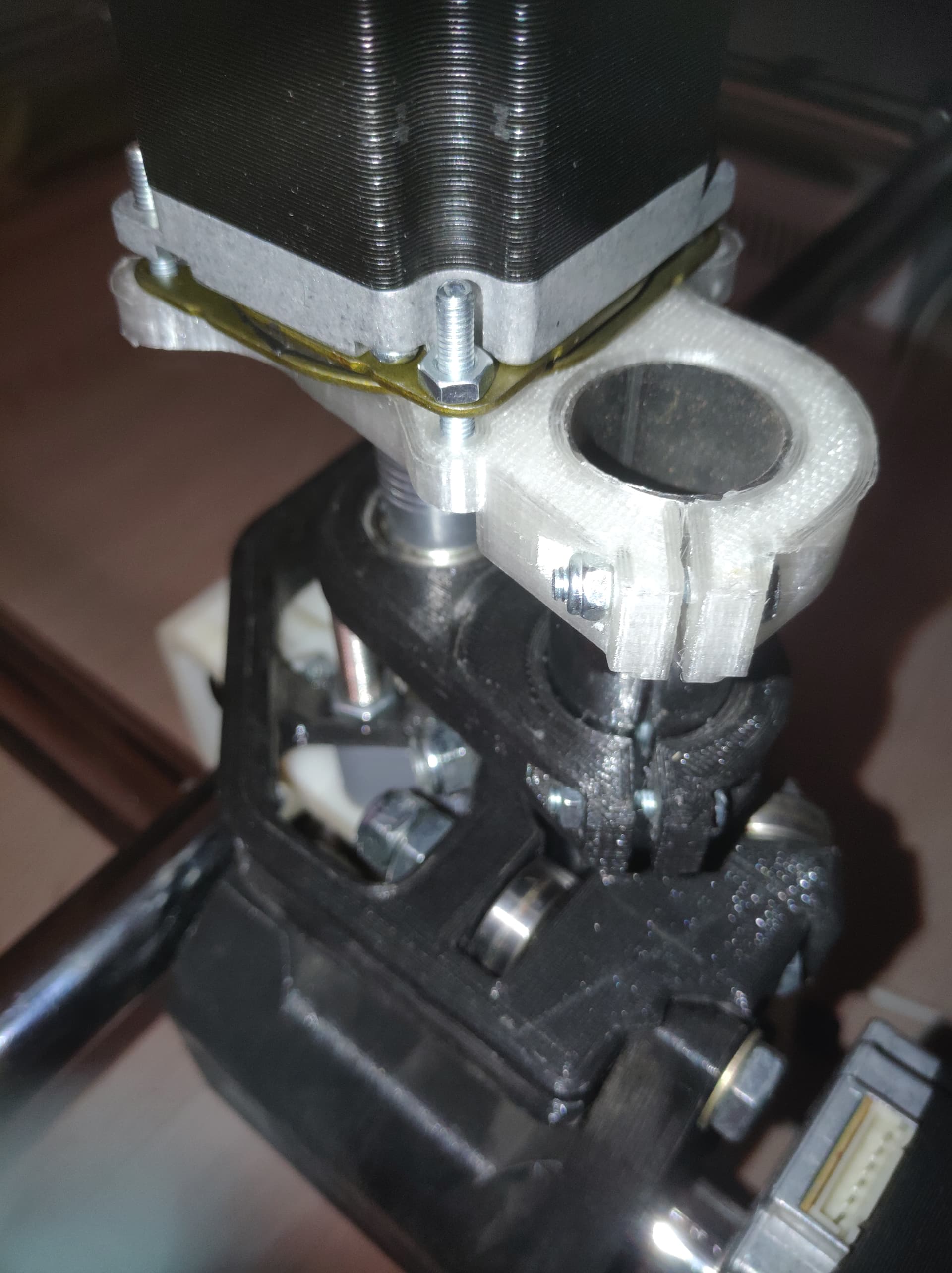
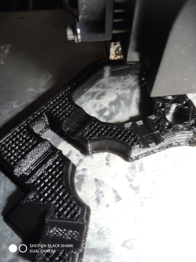
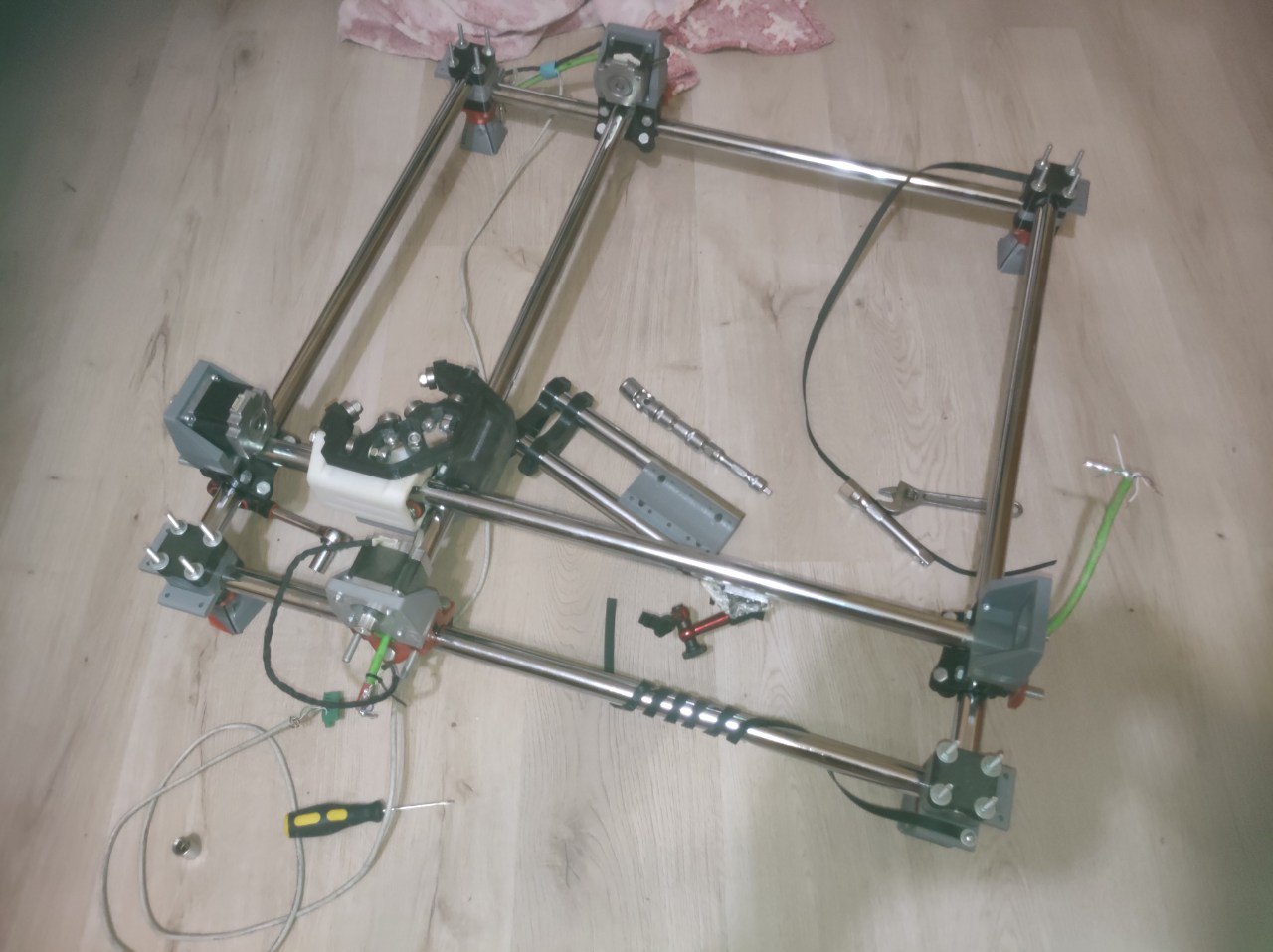
And after that was a long hiatus cuz of job, and I moved to another place where was no place for crafting and storage and so on… MPCNC prototype was left alone at the garage till the modern day and emerged :smiley:

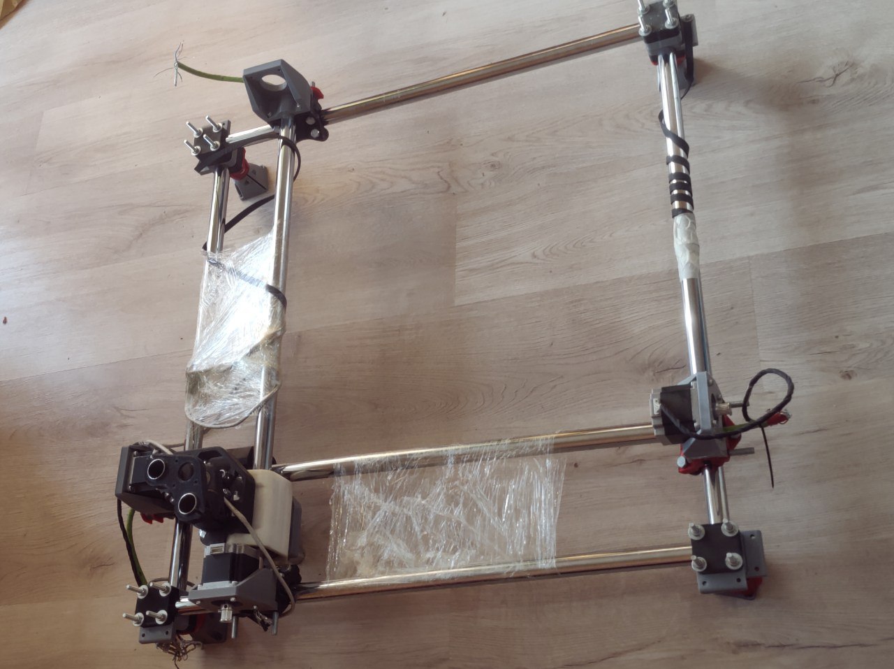
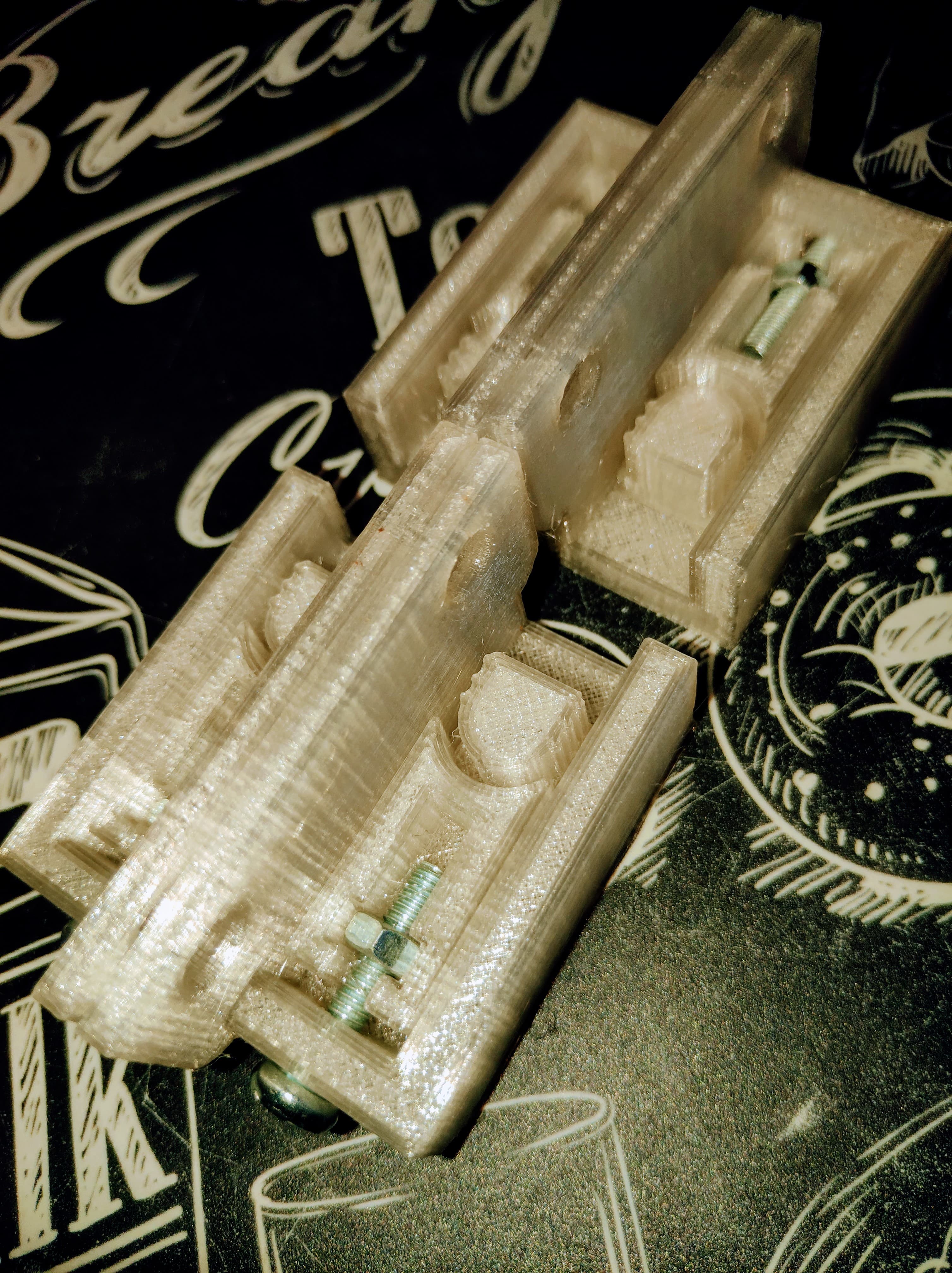
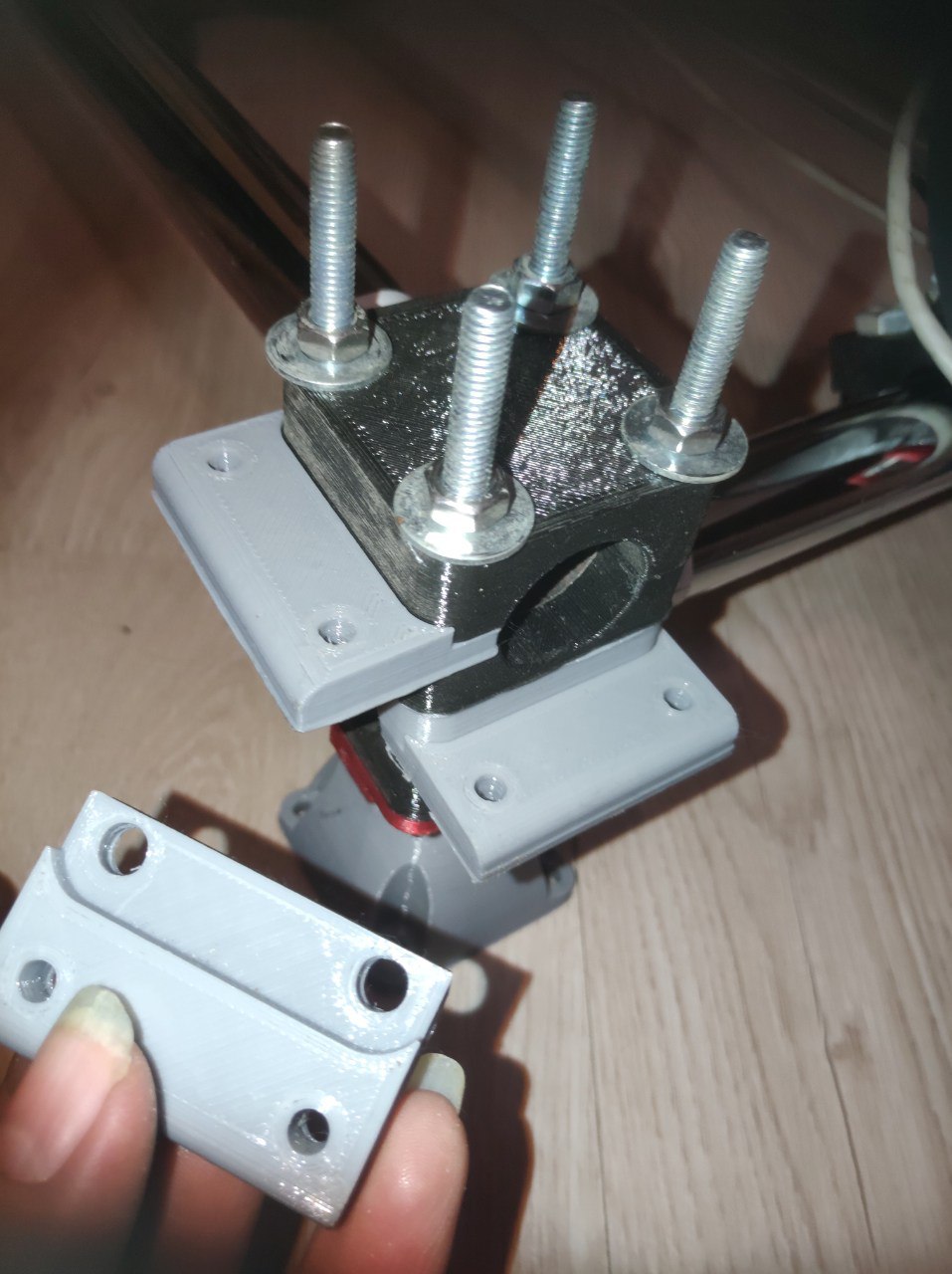
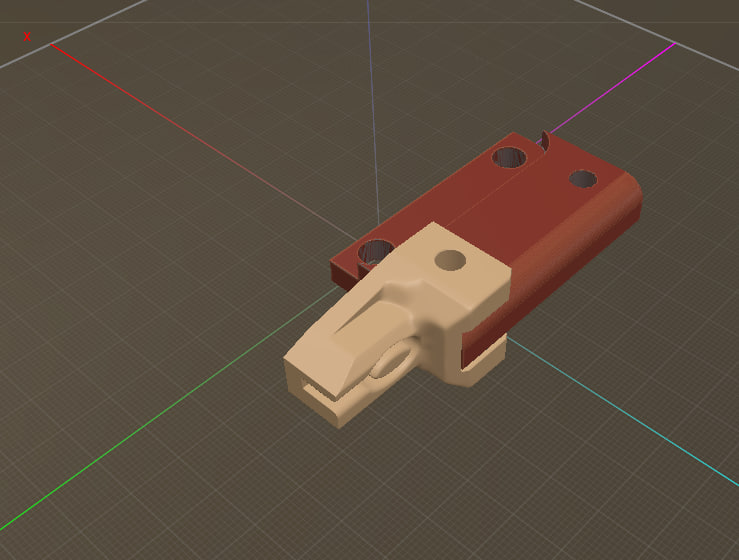
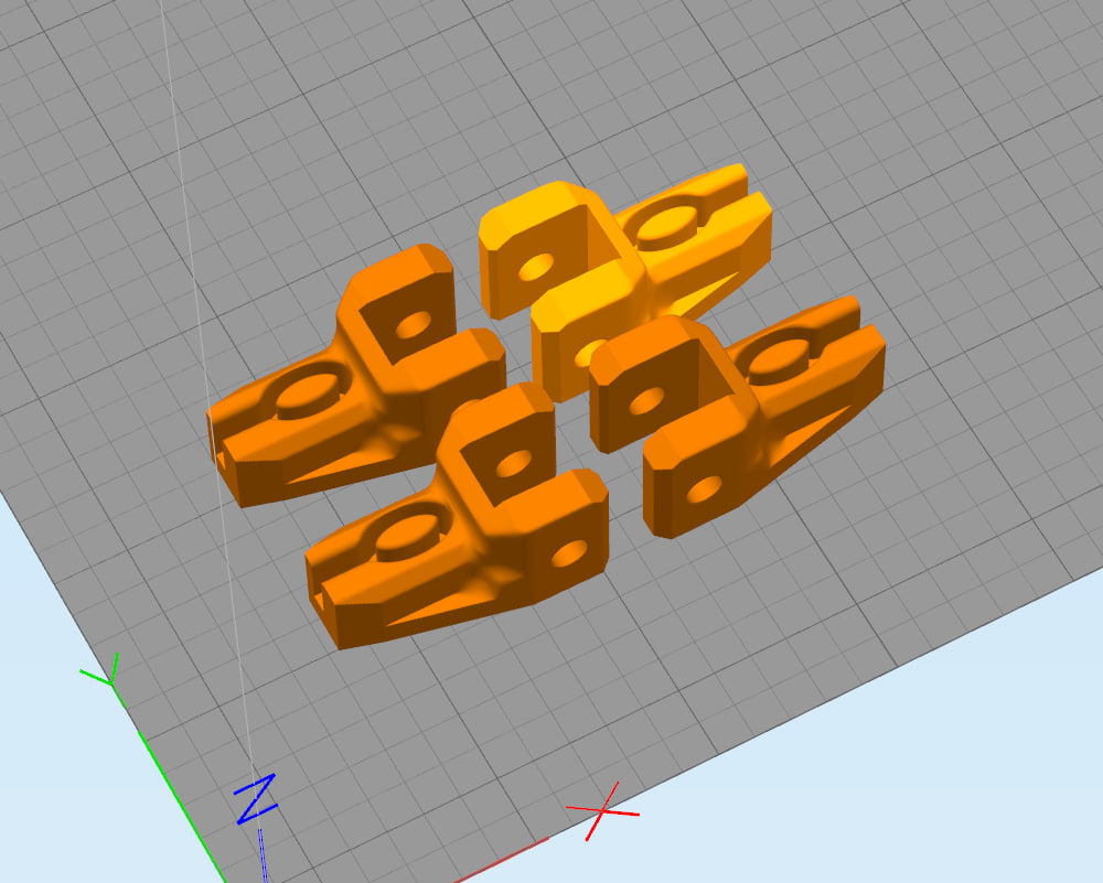
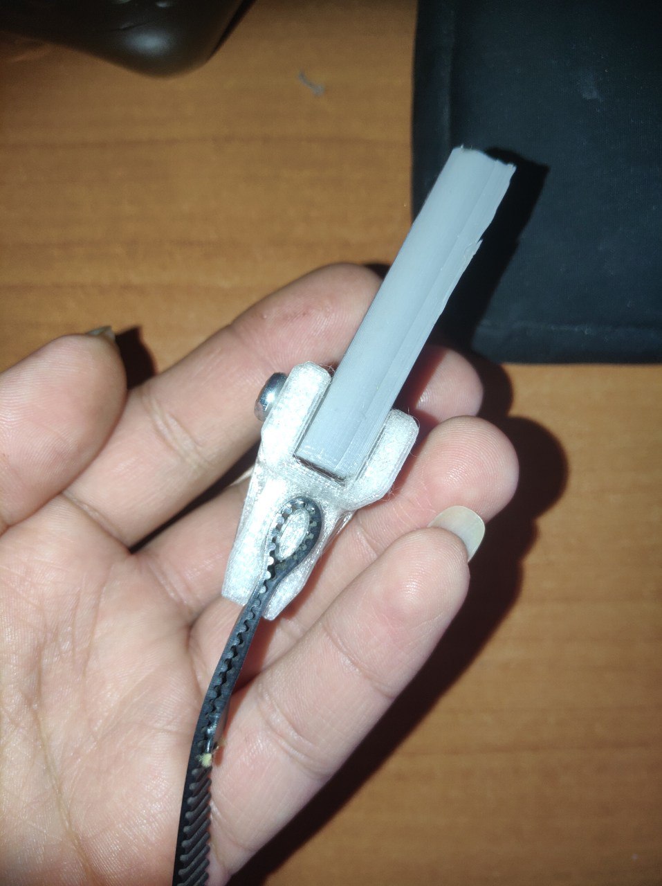
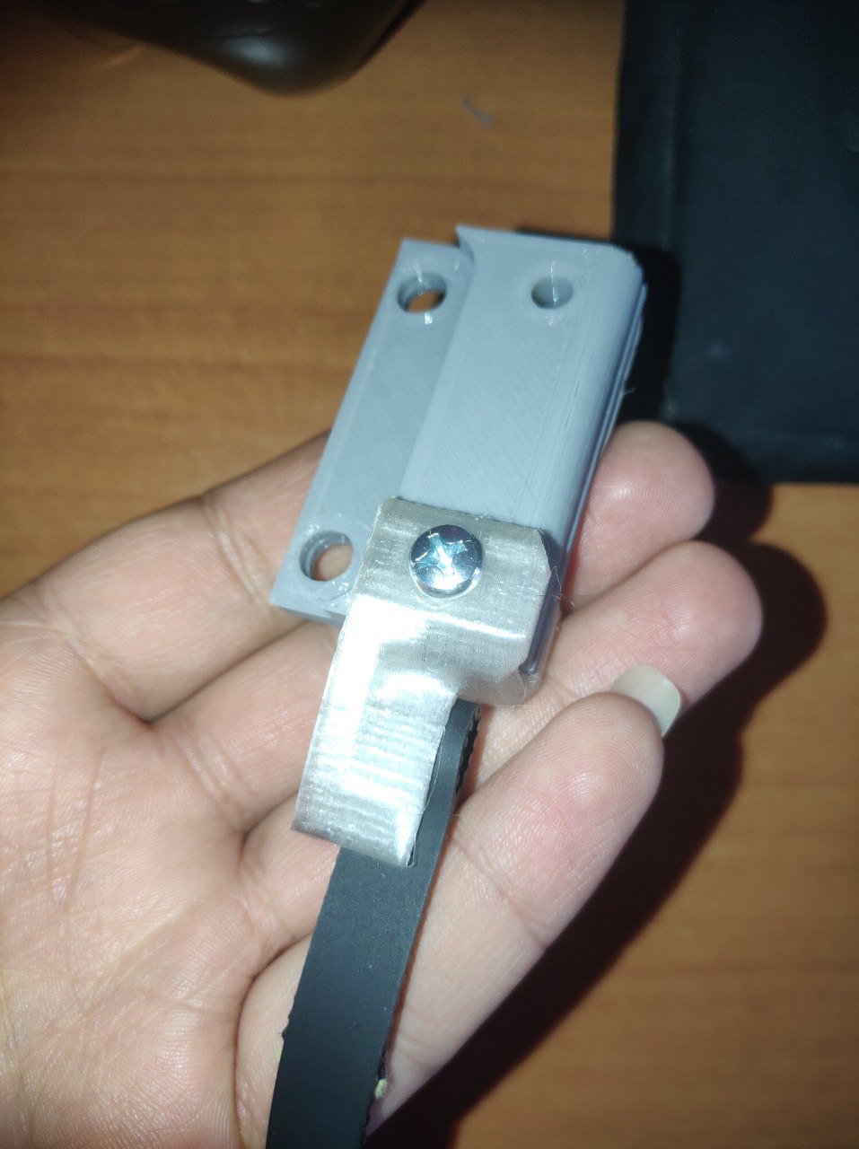
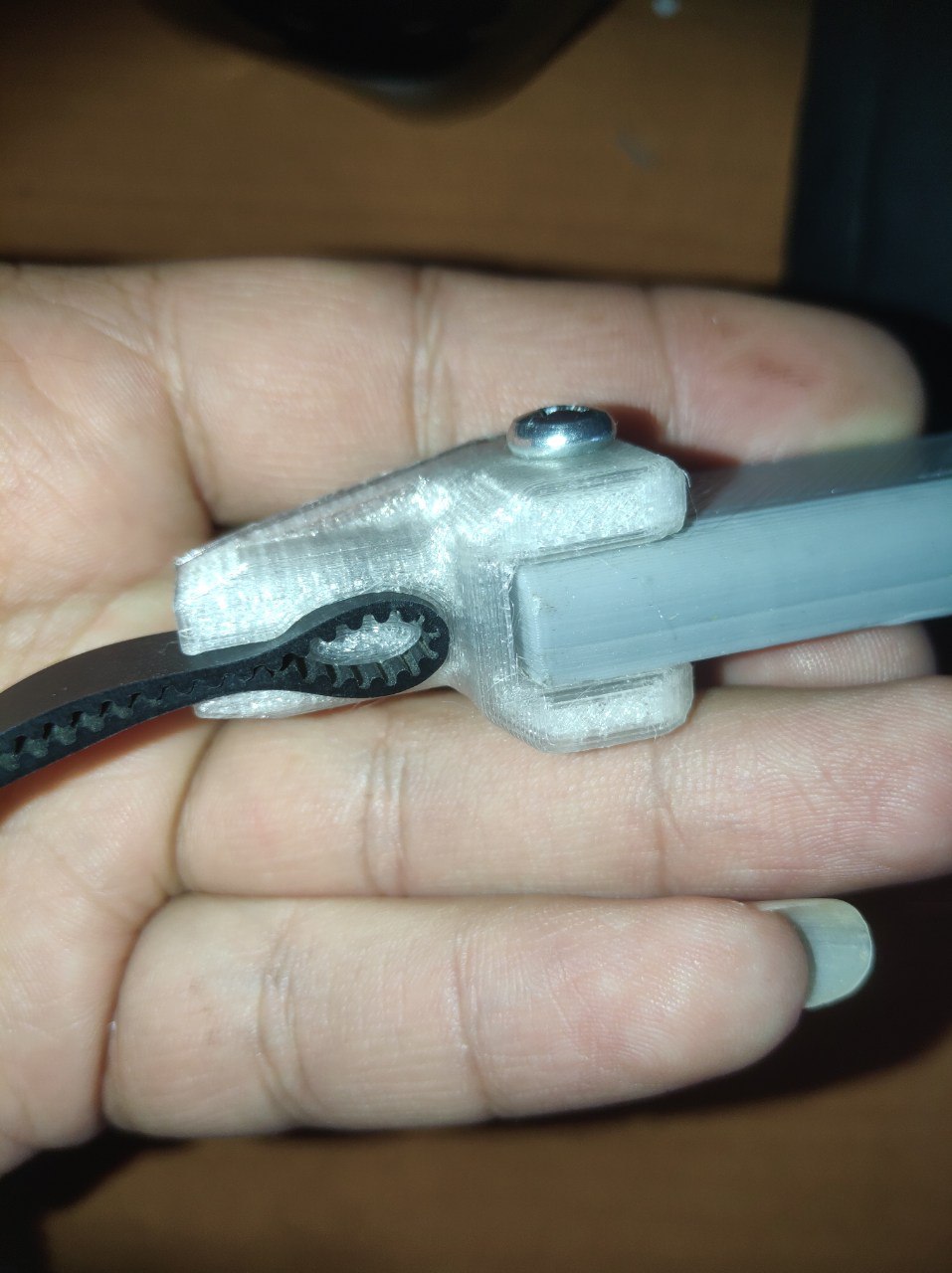
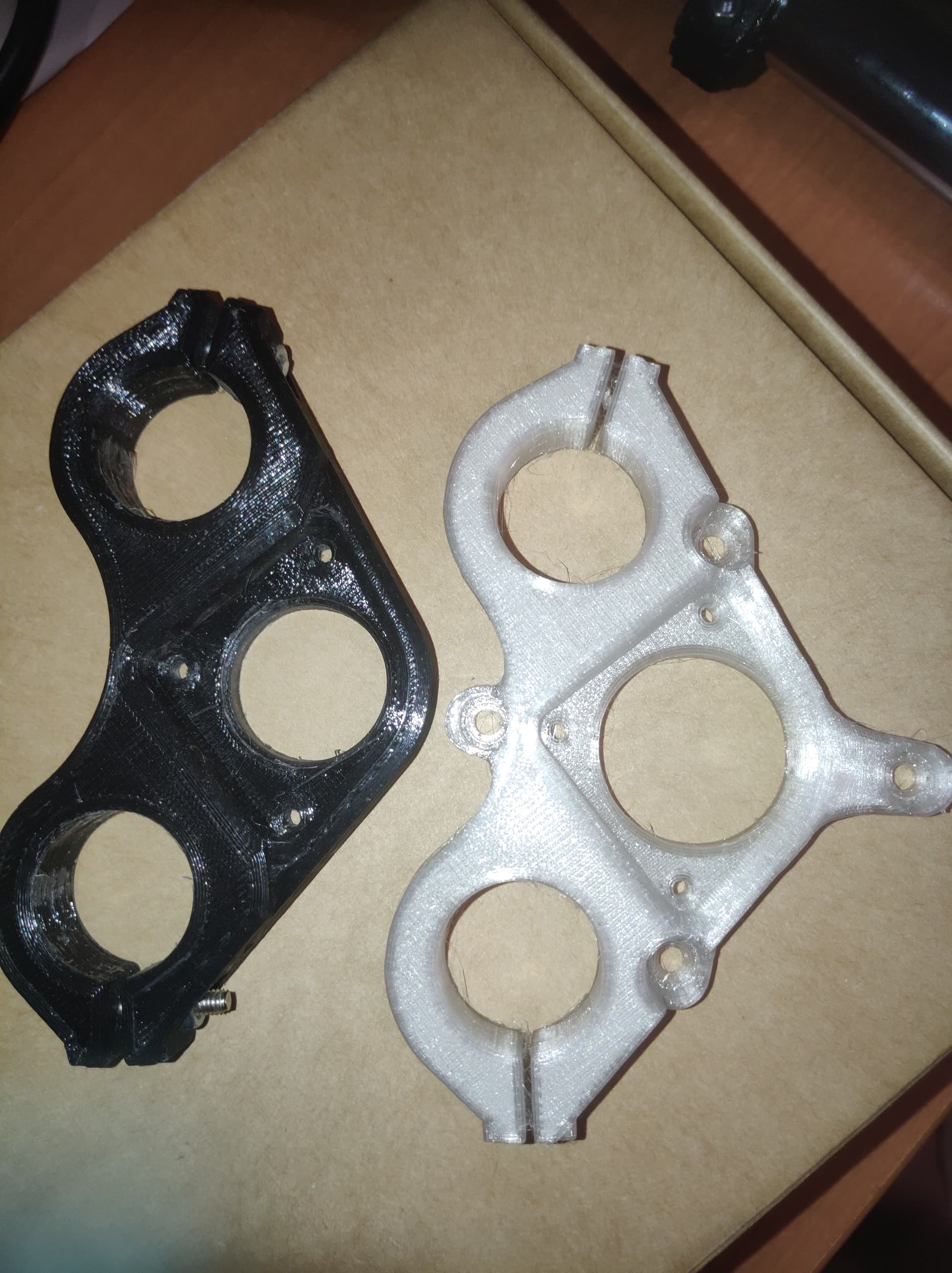
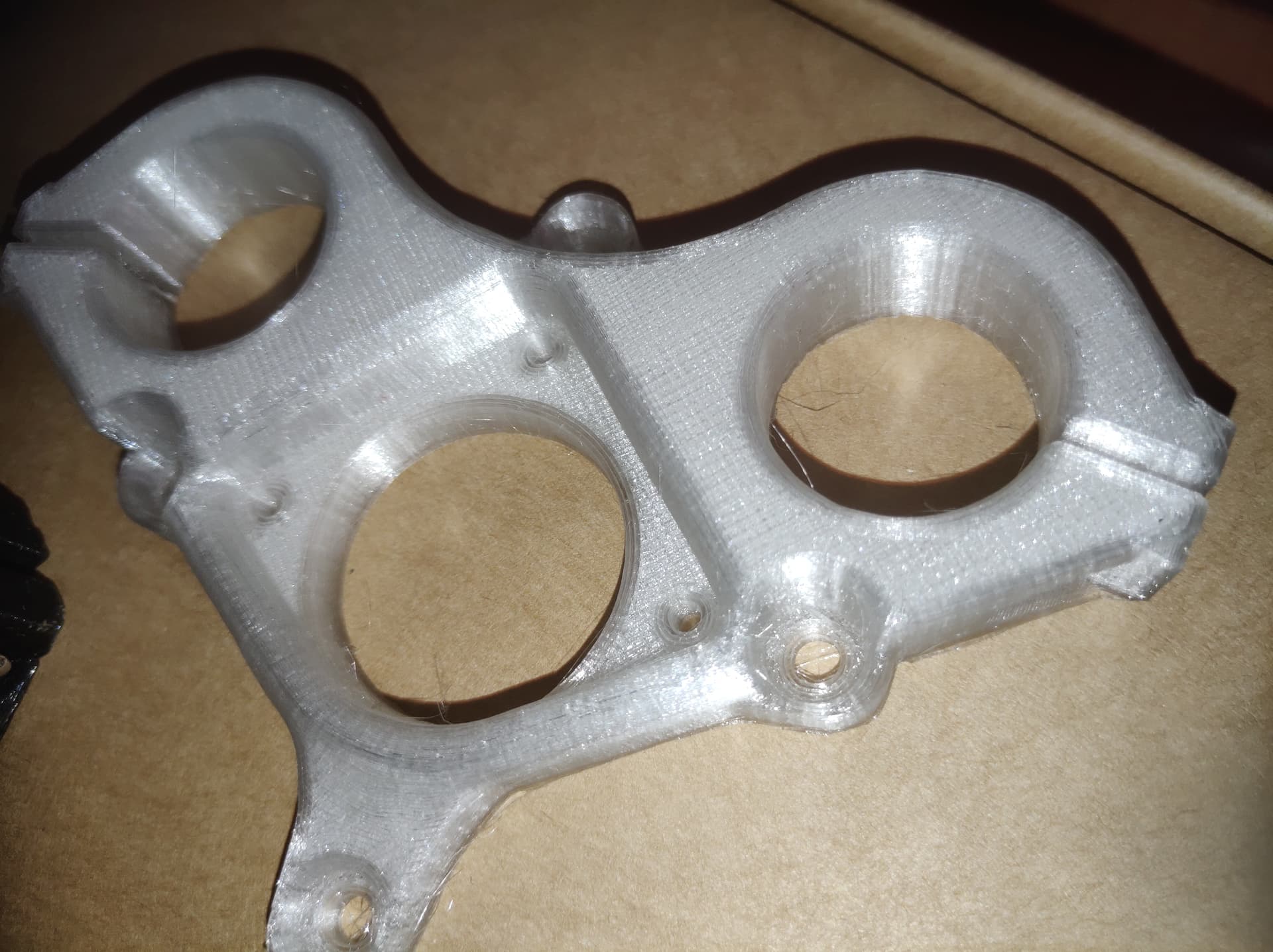
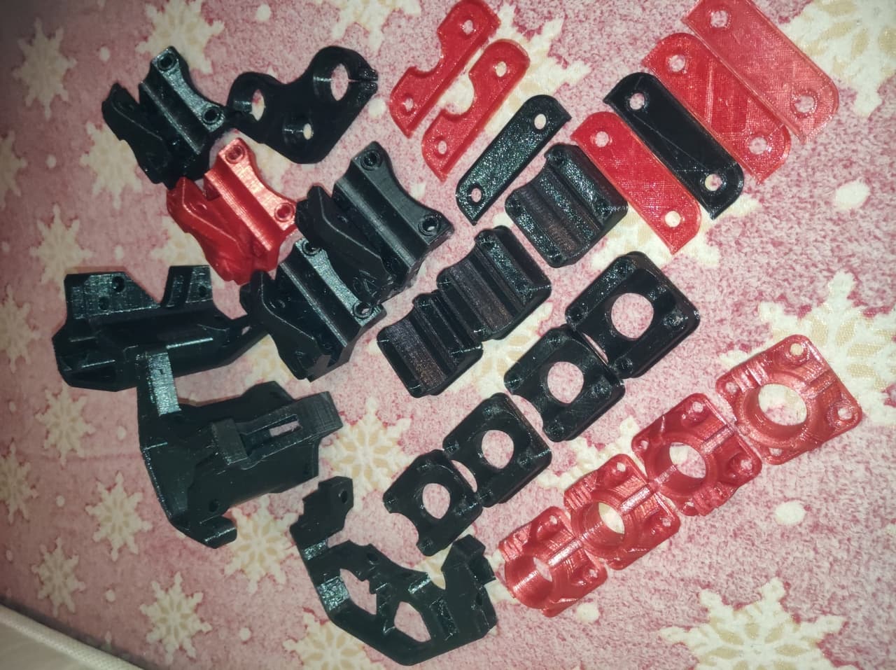
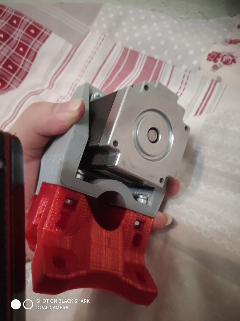
I become smarter from those days so some parts was remade.


I eventually found that a lot of versions are made after my pause: burly, primo and mb somethem betwixt. In this way my version become old paps but I love it and continue my job around it.

Uhuh:

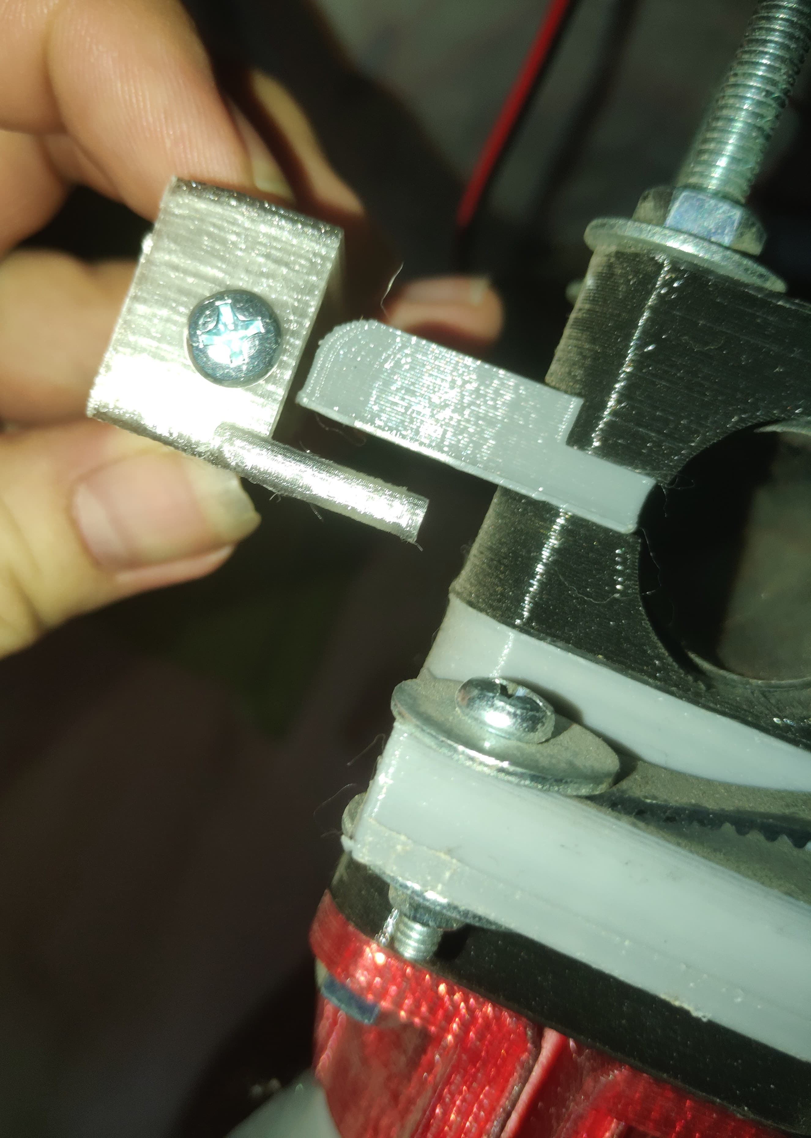
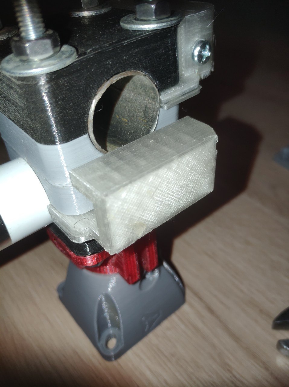
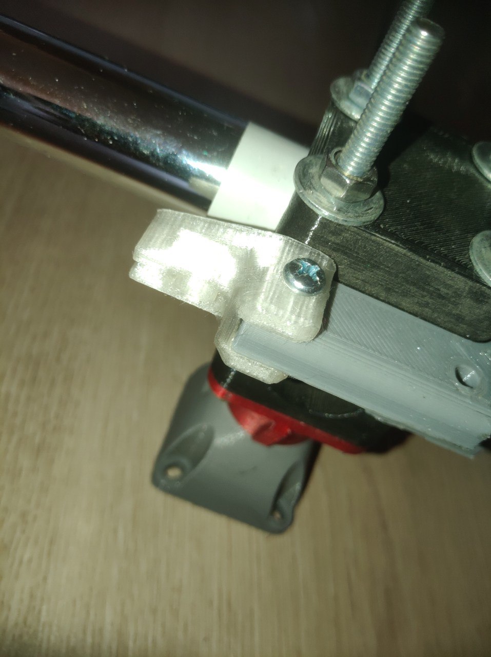
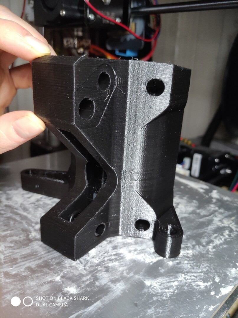
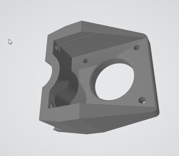
The next steps will be a new Z-axis rail, the old one are skewed, new z-motor mount adapted for nema23, cuz i forget to make a new model based on nema23 concept than I become lazy and stopped on the adaptor 17-to-23 version.

To be continued (Sure if this story is interesting) :innocent:

7 Likes

Ваще заебись, это успех =)

1 Like

Yus, indeed XD Somebody stop me!
For now some progress than!


The basic mount for the rails was disbanded for reason i can’t remember… And I printed the belt tensioning system. But I missed the height of the default one, lame Im…

1 Like

Journey for the belt system continues.
I added the belt tensioners to the 2 corners of the machine, so it looks sexy for now :laughing:

And than I need the receiver part.
There was a blank-looking holders, that used for something else… Mb for my old chain-based solution.

And I become too lazy to print a whole new set, so I quickly make a belt lock module that fit the old blank holders, why not?


Printin’ in progress…

4 Likes

This looks like a really fun build, looking forward to how it’s going to work out though you might consider switchting to the Primo, there were quite a few enhancements.

1 Like

Thx a lot i try to do my best!
Switching to the Primo will equal to make a whole new machine from scratch and it will not fit my nema23 concept and large belts. I will be forced to use nema 17 or remade whole parts in 3d to let the nema23 fit in in. At this way it’s pretty inefficient economically and no fun a lot. May be in future or if I will make a new one for the friends or so on - i will start from Primo! XD

1 Like

Sounds good, keep us posted. Are you British, btw? Your LinkedIn has your company seated in Bristol. I lived there for a few months and loved it.

Btw the progress for today.
I done with the belt locks for the holders and it looks nice on my opinion.


In this way the belt sliding system is absolutely done
First slide :smiling_face_with_three_hearts:

1 Like

Ah I see! Sure i will!
Cheers for Britain and castles! But I’m canadian :slight_smile: Mostly outsource for dev stuff, but in the basic reality the ECLSS engineer I’m.

2 Likes

Woohooh! The belt system are done!

Sameelse I begin the Z-axis part of the gantry. I have no proper coupler for the 8x8mm so I did a 3d version of it and it strong as i not expected.

I tried to make a fast setup to have a great excitement of the workin’ motors but…
The motors move awkwrdly - in turn despite the fact that they were connected in series, first one then the other, and not together, maybe because 12V was not enough for them(datasheet: 24V :sweat_smile:)? Or did I make a mistake somewhere with the connection… In the end, I want to ask, how do you connect your motors, 1 driver for each motor or 1 driver for 2 motors, and they themselves are connected in parallel or also in series, what is your experience in this?
Motor: KM23-C051-V09

Summary


Setup:
Arduino Mega + Ramps 1.4
BIGTREETECH TFT24 V1.1
TB6600

The video with the chain was painful haha. I can’t imagine how noisy that would be running. People would be begging for you to turn on the router to make it stop.

1 Like

Yeah, thats why I back to the belts than XD

Progress for today, I tryed to set the motors to the series and 24v than, they become hot as hell but work. I dont like how they work but it work :laughing:

1 Like

Linda’s MPCNC digest:
I done wiring both of the axis. After a lot of fight I preferred the separated drivers way instead of series connection, where only one driver serves for two motors. For now its 2 drivers per 2 motors, two by two :innocent:

This KM23-C051-v09 are very hot, they reach 80C pretty fast. But with separated system they never goes above the 60C, and there is be good. The next step is the Z-axis.

The life is full of fun XD Today is a Z-day.

I find the old way to hold a nema 23 stepper on the Z-motor holder as inappropriate. And i make a new 3d model of the Z-mount.


And printed:
black is old for nema17 and a new one! White for winners!

Than I assembled the full setup:


In the same time I’m accidently found at the scrape heap a PCB from the broken Xerox 3345 with stepper drivers, pretty interesting.


Its SLA7073MRT unipolar driver that is very powerfull with a cool properties:

Features and dataheet
  • Power supply voltages, VBB: 46 V(max.), 10 to 44 V normal operating range
  • Logic supply voltages, VDD: 3.0 to 5.5 V
  • Maximum output currents: 1 A, 1.5 A, 2 A, 3 A
  • Built-in sequencer
  • Simplified clock-in stepping control
  • Both full/half-stepping
  • Built-in sense resistor, RSInt
  • All variants are pin-compatible for enhanced design flexibility
  • ZIP type 23-pin molded package (SLA package)
  • Self-excitation PWM current control with fixed off-time
  • Built-in synchronous rectifying circuit reduces losses at PWM off
  • Synchronous PWM chopping function prevents motor noise in Hold mode
  • Sleep mode for reducing the IC input current in stand-by state
  • Built-in protection circuitry against motor coil opens/shorts option available


I have an obsession to tame it for my MPCNC (or something else) purpose, why not?

2 Likes