Texas Primo (Upgrading a part Burly/part 525)

1 Like

That does add parts, and the real trick is you are depending on the tension of the bolt to hold the bolt in place, laterally. As the plastic gives over time, it will slip. Compare that to a bolt that is pulling the bearing in tighter, and as you tighten it, it will suck into the tube. The second case could still loosen over time, but the loose is proportional to the screw and plastic give. If you’re depending on the tension to hold it in place, once you reach enough give to slide the bolt to the side, it will go all the way to the side.

An interesting question… there is also the possibility of directly adjusting position/tension like this

Or I’ve also been considering an option with inclined planes. Let’s see if I can describe…
image
This configuration could have a slot (only allowing 1-2 mm perhaps of travel) in the green part, and a circular hole in the red/brown part, and tightening the nut/bolt axially squeezes the red parts and also forces it toward the rail. More complex and easy to over-tighten. Probably not workable but in the spirit of brainstorming perhaps it will inspire a better idea.

1 Like

That is not very out of round at all.

Tensioning is hard. I tried a few options on this one. The easiest is just make the bearings stand off a little shorter on the core for the gantry clamps and then the bolt tension to the core actually brings it closer no added hardware needed…but it already is closer. Heck you can even sand or scrape them down a bit if needed.

We need to wait and see how this goes on other builds. I will also take mine apart again after I finish the 611 mount and see if I can replicate this.

1 Like

As I mentioned before… If my printer can print it, then anyone’s can :slight_smile:

I don’t know if you still consider Primo somewhat beta, but I think anyone building one right now is still a bit on the bleeding edge. I knew I’d probably run into some slight oddities, so it didn’t upset me.

I do seem to be getting the Lion’s share of hiccups on the build, so hopefully I’m taking one for the team and everyone else has better luck.

I’m currently printing a holder for the cable management for the core. Once that’s done I’ll have all my hardware in place. I need to re-wire the Y axis because I didn’t do that when I redid the rest of the wiring last fall. Then I need to decide if I’m going to shoe-horn this thing into my existing enclosure or try to make a new better one. I honestly haven’t measured the feet to see if they’ll even fit on the existing base.

2 Likes

The hardware is now finished. The last thing I wanted to get done was to design a cable run mount. I got that finished earlier today and mounted up.

I had the wife help me move the cnc machine. We were able to lift it up and place it in the current enclosure. I do need to get another piece of 3/4" plywood because the current base isn’t quite big enough for the legs to fit on correctly. I hope to get it moved into the enclosure this weekend. Then I need to finish upgrading the y axis stepper cables.

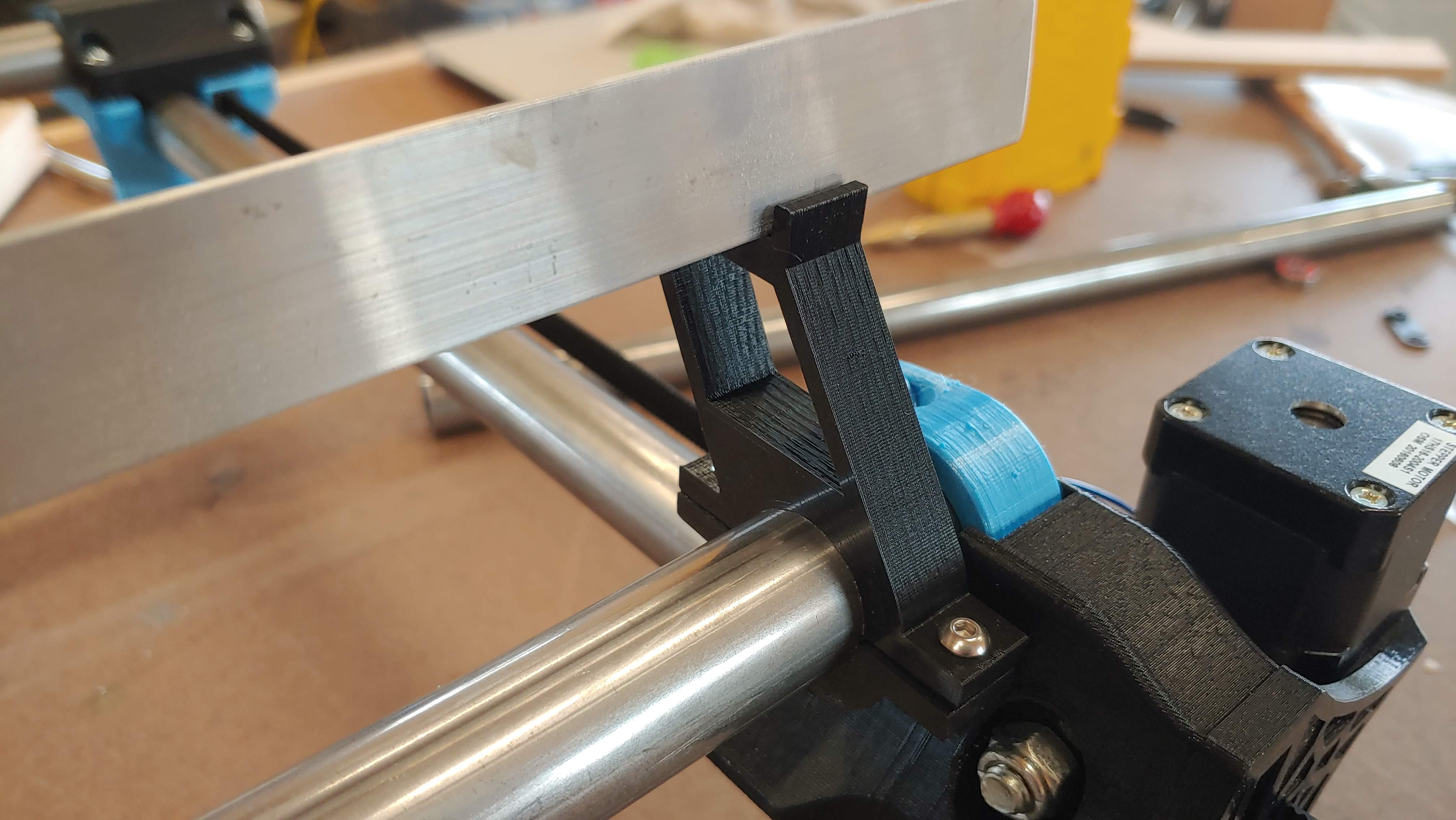
Here’s the cable run mount I came up with:

5 Likes

@niget2002 Looking good! What was your thinking on how you positioned the angle (the vertical leg of the angle is adjacent to the Core in your photos)? I’ve seen another design that had it reversed so the vertical leg was flipped (away from the Core). It looks like you could easily flip it on your design without any part changes. I just wanted to get input on if one orientation was better than the other.

As with most things I design: TLAR :slight_smile:

I mean… I really don’t think it matters. It just happens to be the way I had it on my other machine, so that’s the way I put it on this one. The cables are going to be held onto the plate using zip ties.

I guess on this machine it might matter some. I tried my hardest to keep the Flat part of the angle aluminum as close to the core as possible. Depending on how you install the zip ties, they could interfere with the core if it was flipped the other way. My plan is to drill small holes in the bottom of the angle aluminum and use the zip tie out over the outer edge and loop back to the hole to hold the cables on.

And then from the aesthetics side, I think it just looks better to hide the cable chain.

1 Like

Thanks for the input! I may need to rethink my design since my bracket is fixed facing the angle the other way. This will be my first build so I’m using thought experiments and the forum’s knowledge to guide my direction. :grin:

Or just use my brackets :slight_smile:

1 Like

Lol. I was including some keystone geometry in my design to use the CAT5 cable routing concept but I guess I could add that to your design. Will give it some thought. :grin:

Progress will be slow the next few days as I work around other projects.

I did sneak out to the shop on my lunch break and get a new build platform installed in the old enclosure. Had to bump up in length and width to fit the new feet. Luckily the enclosure is plenty wide for the steppers to still fit and run back and forth correctly (I think). I’m just hoping our test fitting last night was true.

I used 3/4" exterior grade plywood that I then sanded down so that I don’t get splinters. The spoilboard will be surfaced by the router, so this surface being perfectly flat is a little less of an issue.

I may end up needing to cut longer legs, though. I need to redo the math and make sure I have the clearance I want with the current legs.

I also have plans to move the existing power supply and on/off switch to a better location.

Gonna try to make some progress on the primo tonight, but first gotta turn this guy on in the shop…

1 Like

I couldn’t wait to get it moving…

First Moves! Still need to wire the Y axis, but the X and Z move. This machine seems to be quite a bit quieter than the last one.

6 Likes

You had conduit before, right? I wonder if that was the source of the noise.

I like that you took a really long time to try the Burly/T8 upgrades, but you are right on the bleeding edge with the Primo. This is fun to watch.

@niget2002 Can you share a link to the quick disconnect connectors you’re using?

Sure thing.

Here’s the 4 pin connectors.

I use these on my panels. The silver connector is one of these too, but a two pin for the spindle.

https://www.amazon.com/dp/B07D7SHKGK?ref=ppx_pop_mob_ap_share

I finished wiring up the Y axis. I need to do some wire management.

I also discovered that my controller is too low. Good thing I planned on moving it.

2 Likes

There she sits. All put back together. Just need to drop a spoil board on it and make some dust.

Cable management took a couple of tries. I had things too tight and the Y axis was sticking.

8 Likes

Get. It. Dirty. :+1:

Looks great.

My next shop WILL have ac.

1 Like