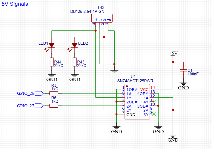
That is giving you level conversion from the ESP-32s 3.3V IO to 5V level. Probably also protcting the ESP-32 from badness on the output side from silly user tricks.
LED is mildly helpful but could go away in my opinion.
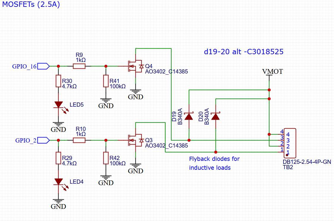
I’m not a fan of the low side switched MOSFETs.
Mildly helpful. Could go away.
Yes. Or you could look at the utility using an Airedale gives you. Probably a different topic but the next Jackpot should get the FluidNC style RJ12 UART connector to facilitate this kind of IO expansion.
You could nuke all that MOSFET nonsense and have another footprint for a bart-style expansion header.
I’ll see what I can do to change the mosfets, good catch.
Forcing someone to buy a module and another board to get a single output isn’t ideal. An SSR, or a laser is pretty common use for the outputs.
I think to save the one pin we need I will get rid of one mosfet output.
I am pretty sure I could handle a jumper selectable output just not really sure it’s needed.
Thanks for the explanation, the level shift is the part I wasn’t considering. But do we need that? A laser usually work fine with 3.3-5v pwm/ttl, same with WLED, and a ssr.
The level shift and the protection of the ESP-32 are both good features. The 3rd (and 4th) input to U1 are not presently used. You could easily move one of the MOSFET GPIOs over to the 3A input of U1 and have a 3rd output.
You could put a footprint for a pin on the GPIO side of R3 and R6 so if a user wants to break out the GPIO directly they could (a user might even then remove that series resistor)
You can protect against inductive loads with high or low side switches.
It’s my opinion that the disadvantage of low side switches is that you pass VMOT straight through to the output pins on the board, so if a user shorts that output you can blow your VMOT power supply or burn traces on the jackpot.
A valid counter argument is that if you short power to the ground pins you get the same result.
My counter-counter argument is you almost never find people randomly finding ways to put power supply rails into grounds, where you find people shorting things to ground all the time.
So can I just set up 3 outputs, all mosfets and make the output voltage changeable, 5v or input level? Simplified and options all in one? I understand that would make LED’s more complicated but I am willing to give those up.
I’d vote all three outputs default to 5V from U1, no MOSFET on the jackpot. With the option to break in to the GPIO directly if needed.
You can always use a 5V relay, SSR, or your own driver if you need them using one of those pins.
I’m not sure switching output level between 5V and 3V3 is valuable for the Jackpot use case, but I am sure there are 5V peripherals like those LEDs that need 5V.
Edit: I’d also consider making the outputs pluggable connectors instead of pins.
I know on my Primo I use 1 5v output to control the laser and one 24v output to control the air assist. So going to only 5v will limit people in what they can do.
Jim why not high side switch 3 mosfets with selectable voltage, 5V or 24V? Remember, I know very little beyond the general idea of what each component does So I very easily could be missing something.
Aren’t there a ton more outputs available from the i2s shift register? There should be plenty for generic switching but i2s outputs can’t be used for PWM, so at least one or maybe two outputs should be gpio.