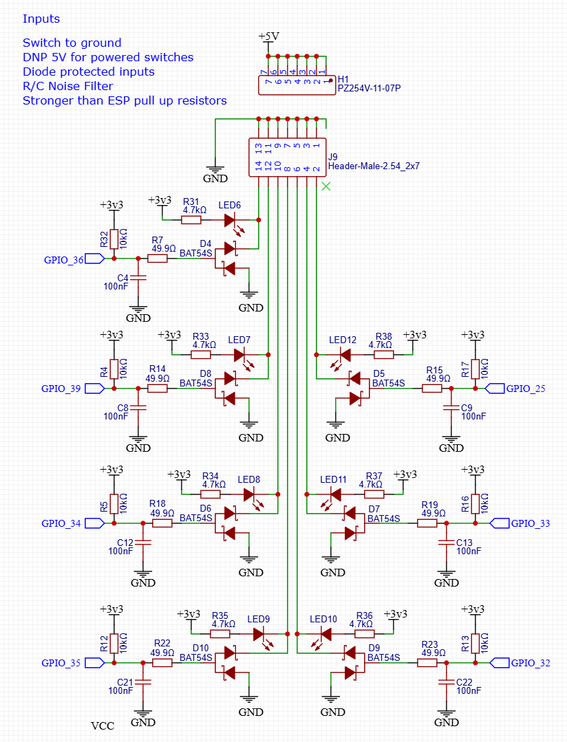
-7 inputs seems great to me. We typically use 6, nice to have a spare?? or should we go down to 6 as I have never used the spare. I can’t think of a time we have ever helped someone use the spare. Estop, door safety switch?
Looks like 7 is good, we will need a spare pin from elsewhere.
No complaints or other suggestions the diodes stay.
-The LED’s? I know we all love LED’s but honestly the $limits command is amazing, easy and tells you more info.
Reasults- Keeping the extra input is a good idea, popping out at least one pin (if not all) pre-diode is legit so the pins can be used for other things (at least the non-input only pins).
In this we also got the idea to possibly share the module port pins with something else.
The indicator LED’s are a question mark, $Limits is a fantastic idea for beginners to get over the fear of the terminal.
Fun, but It could be a plugin board, or some through holes waiting to be populated with an extension.
I think them being on or off makes them not as usefull as I expected, meaning the probe is off and the end stops are on. A little wonky.
The Current jackpot will not be getting erased from existence, in a new more cost-effective board are these really necessary? (if we had integrated esp or drivers, we will need some space).
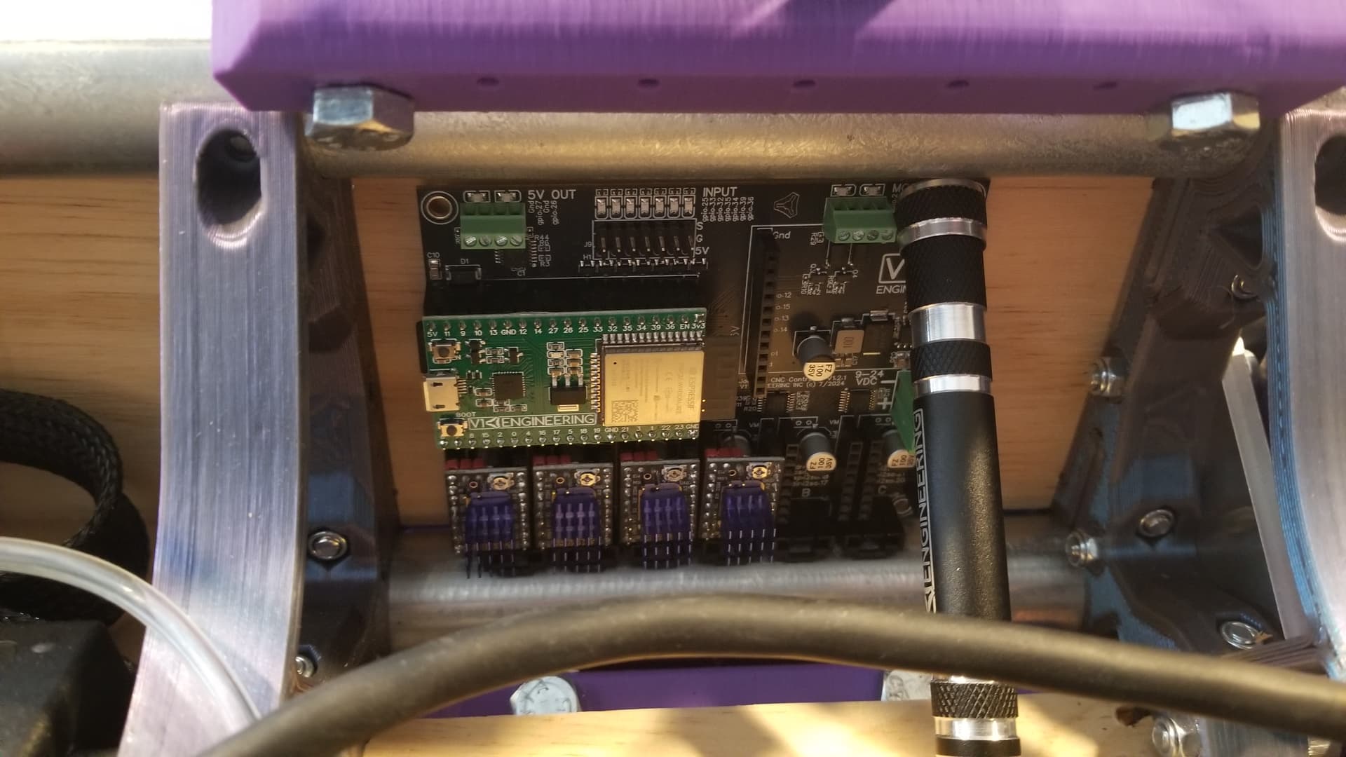
My board lives in a covered box, I do not see the lights.
On that note the 5V led is 100% gone, waste of time and space. The esp’s all have a power indicator LED (if we integrate yes I will add some sort of 3.3 or 5v or power indicator).
I have several new wire mounts coming for testing. That is actually the reason I am making a change in the first place.
Remember the current jackpot is not going away. I need a board I can use for international sales that I do not need to touch. Tariffs are making things brutal. There is simply no way around the fact that things can not enter the US, get handled and shipped out again. Every other non-US CNC company will swallow me alive.
I recall a few times where folks have used the spare because they blew an IO- recently someone with no grounding of the dust collection springs to mind.
These inputs are reasonably well thought out and protected for enstop use, but the thing that bums me out about them is there isn’t a good way to NOT have these be pulled up GPIOs.
I wonder if there could be footprint to optionally cut a trace and install a pin so that I get back up to 7 GPIOs to use for other things. This doesn’t have to be expensive, just give me a spot to cut a trace feature and manually solder a pin.
Note also there’s the whole discussion about FluidNC IO expansion which is now possible via the UART side of things with the awesome STM-32 IO expander (AKA the Airedale board.)
Consider some footprint to make it easier to do the fiber optic indicators that Jamie an Aza have done. (Maybe a registration hole or something?)
Are wiring connector input options in-scope for this topic?
Guessing genuine Molex part pricing will be too high for the current board you’re designing, but maybe lcsc has functionally comparable cheaper alternatives to parts PRUSA-MOLEX recently shared, with case study details/marketing… about how they’re using:
I should probably post this to a “other stuff” sub topic, but…
During LR4 beta, wondered if strut mounted, or strut semi-enclosed PCB mount could help reduce/avoid overall 3D printed material cost/time for a dedicated enclosure box. This could also help provide visual feedback to users if PCB has reverse LEDs (still top mounted to avoid extra cost of double sided assembly) and cutout window in Strut.
Maybe box cost isn’t a concern if you’re changing how the box is designed/manufactured for scale, and/or, you’re modifying PCB to fit in a commonly available enclosure box, e.g 2 gang electrical outlet.
With the sheer number of these boards being sold I have to assume V1 machines are only a part of what they are being used for. Making things as specific as led windows might not work for a lot of builds, plus I do not want to get locked in for other machines.
More general swiss army knife do it all motion controller.
This and the regular module fill the gaps of anything we might WANT, that is not included. The module socket is taking up 4 precious gpio.
This is why I am trying to boil down this to the basics. hopefully we regain a pin or two, save some money.
What is the most robust cost effective board that does everything 90% of the V1 users need without making it not ideal for users that are not using this on a V1 machine.
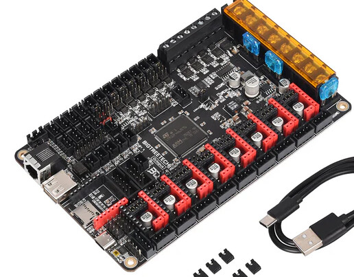
There are a huge number of FluidNC boards now. That are built for specific tasks. That market is covered. We have to be honest here. The V1 Market is the budget conscious maker. The one that THINKS this might, just barely, function until they can save up for a $30k machine. The maker that asks me to keep the bag of 5/16th’s nuts to save them a dollar because they have them on hand. I can not speak to why the non-V1 people buy this board over an official FluidNC board, I have to assume price to feature ratio.
Less unique components saves me time in figuring out a replacement when they go out of stock, and saves money in manufacture.
Built in esp’s and drivers saves me time in assembling the boards, sourcing, inventory, tariffs, and a little bit of cost in manufacture since it is one board not three.
Making sure things are not over specced saves a tiny bit of cost.
Making sure we are not just adding things to add things. I know we can and once we do it is just extra pennies but I value efficiency in all aspects.
Using popular components makes sure they are always in stock, which saves time, or have replacements available.
Lower BOM cost saves cost in manufacturing, elecrow mark up, and distribution costs.
Time is by far the largest cost in the Jackpot, sourcing, Assembling, and testing the jackpot, the ESP32, and the drivers adds the most cost to the board.
More of a basic board, not a do everything. A basic CNC Board. The FluidNC modules are what make it so appealing to me. We can have it all without everyone paying for it all.