My build is on hold while I wait for different M8 and M5 screws to arrive. I also had to guess on some wire and missed the crimp connectors.
Suggestions:
Be specific that the M8 need to be hex head bolts.
Be specific that the M5 need to have a round head AND specify the maximum head diameter.
List the crimp connectors for the limit switches in the BOM.
List the end stop wire in the BOM. Specify stranded with silicone jacket. Ideally include the total length needed for a 4’x8’ build. (The wires in the assembly pictures were maybe tinned with solder before crimping? Maybe solid core? I can’t tell from the pictures. )
I’m using metric hardware so this doesn’t impact me, but the listings of “machine screws” in the US equivalent column should list the diameter, thread pitch, and length in SAE units.
How I got hung up: I ordered Flat Head Hex Socket Cap Screws for the M8 and M5 bolts/screws. If I had looked very closely at the assembly pictures for the YZ plates I could have determined that hex head M8 is required but I only looked at the first few pictures of the Core where the hex head is not required and assumed that held for the rest of the parts. IMO that amount of inspection of the build pictures shouldn’t be needed, the BOM should specify. It’s worth noting that hex head M8 is not common among the search results for “M8 bolt 40mm” or “M8 screw 40mm” on either Amazon or AliExpress. They can be found but the search results are dominated by various types of round heads.
For the M5 I don’t think I would have thought about the head on the flat head screws being too big to fit in the holes so that dimension really should be in the BOM.
I have about $20 of screws for the hardware drawer and I can get replacements relatively quickly, but this delayed the process by several days. Hopefully these small changes to the BOM can help others avoid this issue.
Related, is it possible to directly submit changes to the documentation by a pull request or something? I already have some notes to improve clarity from the little bit of assembly I was able to do.
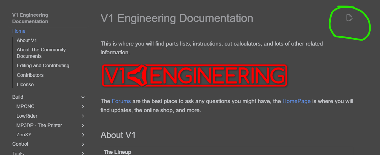
See the page here: V1 Engineering Documentation
Scroll down and there is a good description of the community documentation.
One of the more difficult tasks in a community like this one is writing/reviewing/revising the documentation. We’ve all collectively built these machines and helped people build them. We lose track of what it was like not to have context and frame of reference when new to them.
Thank you for offering to submit a pull request to improve the documentation.
I would highly recommend soldering. I was following the Docs and tried folding over the wire and crimping the connectors. 1 out of 5 worked! So I cut all the connectors off and soldered them. 5 out of 5 work!
Unfortunately, I do have limited time, one man company. Currently, the images and instructions cater more to purchased kits. When self sourcing, I do highly recommend looking at a few of the images to get a sense of what you are looking for.
When I do finally finish the LR4 instructions I will revisit some of these finer details.
Otherwise you can get your changes in right now by helping out and making the edits in the instructions and submitting them for approval. This will help you, me and anyone else self sourcing in the future for years to come. This is a community project and getting a little help is so appreciated.