Being that the struts are the length of the gantry toobz, at approximately 55” and my cut area is 48”x48”, does anyone have suggestion/insight for achieving the profile of the struts?
2 Likes
@Tokoloshe put up a video on how to do it…
2 Likes
Or alternatively you can make the y bigger temporarily
5 Likes
Orient the cut on the diagonal?
1 Like
I did mine diagonally. The flipping method looks promising. I had to convert the SVG from the LR4 generator to DXF via inkscape, before I could import into Fusion for rotating and to make sure it’d fit on my (~4x4) table, exported to DXF 1 at a time, and back to Estlcam (which I think can rotate anyway, just wanted to double check that it’d fit.)

2 Likes
Can’t these just be cut on a table saw with a dado stack?
Yes. But you’ll never get the m5 holes in as accurately as the cnc can. And that is what sets where your braces are and keeps everything lined up.
2 Likes
Never say never ![]() A quick 3d printed jig (like the temp strut) would take care of that.
A quick 3d printed jig (like the temp strut) would take care of that.
1 Like
Very possible. Until your drill bit grabs and takes a chunk out of your 3d printed jig and now you have to print another one lol.
There are many ways you can do this. But the machine is designed to cut them its self for the most accurate outcome.
1 Like
It is possible to rotate with Estlcam. I used it when I cut the LR3 struts diagonally.
1 Like
Shoot i meant to have this referenced!!
I just did mine in 3rds.
See here, He flipped them with the help of locator holes.
I myself used the bolt holes already there. I then changed positions easily, with 4 reference points.
Zeroed it at first, but then in Estlcam I kept using the lower left bolt hole (In the area I was cutting) as my zero.

these are SUPERB machines!
Guess i did not save the project, but here is how it was done (just recreated it quickly is all)
Remember to drill the first 4 holes deep into table for Reference!
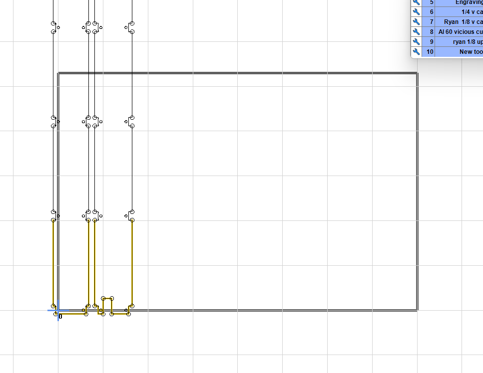
I need to add, i manually removed z probe,etc in file 2 and 3, Philipp was key here, you do not want to change zero at all from file 1 to 2 to 3
4 Likes