Good day,
I need a bit of advice. First test of the mpcnc. There is a lot of vibration on the x and y axis almost like it’s skipping steps and binding. It moves relative smooth when moved with the hand.
Inshort,
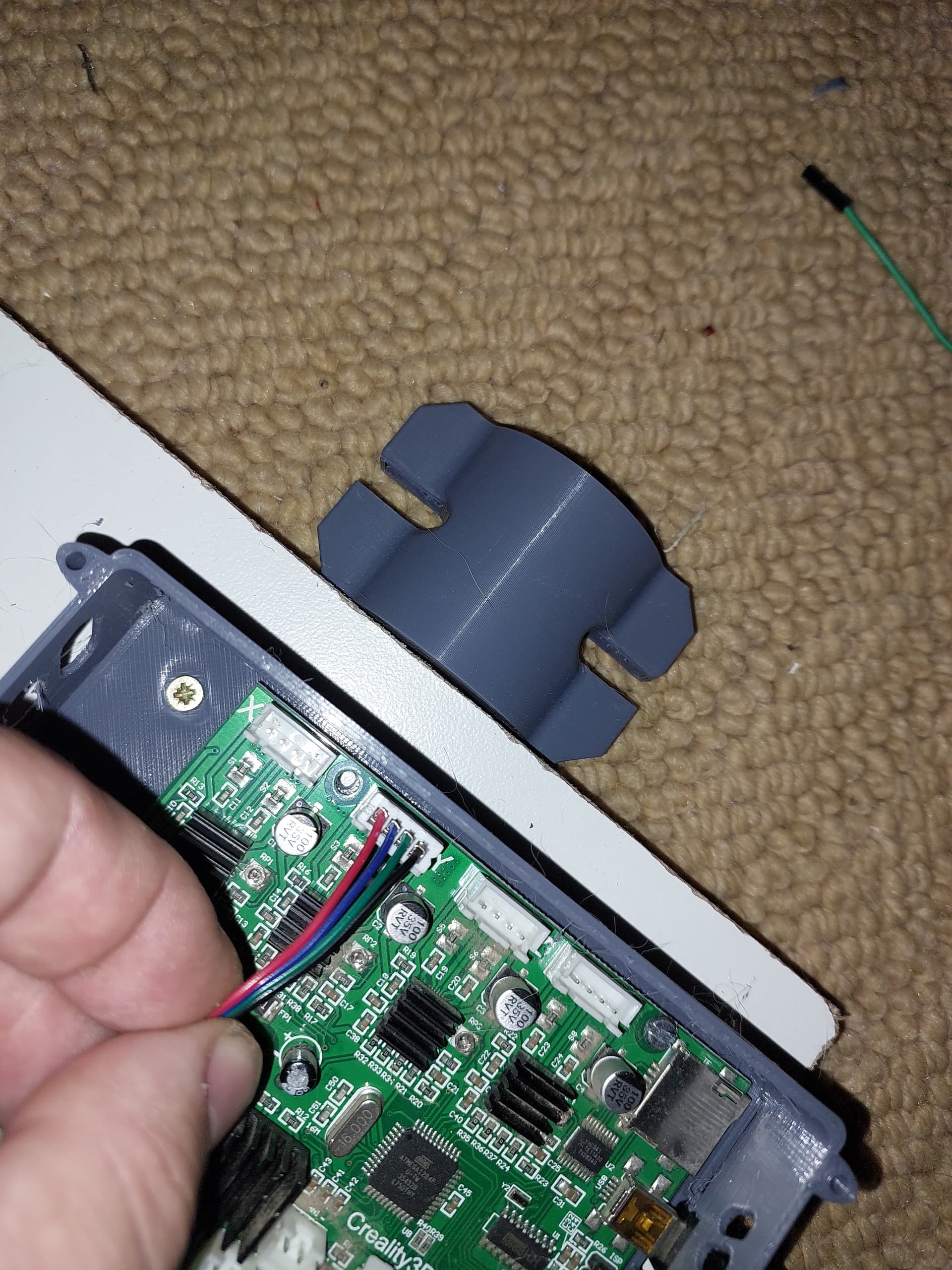
Using a creality board. The stepper motors is wired in series.
It seems like the motors is binding. My plan is to break it down and start again making sure it’s square again. It was 100 square before I added the belts.
Followed the steps exactly.
Please any advice to what the possible problem can be.
Check to see if you have a stepper reversed. If one is trying to go one way and the other the opposite way it will cause what your seeing. Try reversing one motor and then move that axis. If it moves the wrong direction then reverse both. Make sure to power down the board before changing any wiring.
Nope. Only tested it at slower speeds. Both x and y axis. Motors look like they are running in the correct direction. Will check wiring. Z axis smooth no problems.
Yes. Will triple check.
Nope. Will check that. Suggested current?
Yes. But a little bit tight. Struggled to square it. I suspect it contributes.
At least with X (the axis going from left ro tight in the video) your stepper on the left does not seem to do anything. The stepper on the bottom right starts to move and drags the other one behind. You should check whether the other one moves at all and if it does whether the grub screws are tightenend.
Three (the markdown is trying to make this a 2). It depends on the control board you use. But you need to set the current. You want it high enough to not skip steps, but not so high that the motors heat up over 50C. Something in the 800mA range is a good starting place, but it will depend on your steppers.
My guess is that it is one of these. But check the grub screws anyway.
Okay. I triple checked wiring.
Added a diagram of my wiring.
So the problem better defined. Motor a turns in the correct manner. Motor B vibrates.
My plane is to completely redo the wiring but want to confirm first. I looked at the diagram om the examples many times. Suspect I wired something wrong or I got the pin out on the stepper driver wrong.
I am not sure whether you can do it that way. I think you are supposed to split them before reaching the motors: Wiring The Steppers - V1 Engineering Documentation (You have to click “Archive” at the bottom!)
It may not be easy to see, but that is what he did, Philipp. I’m not sure the coils are correct, but it looks right to me. You may not be used to the series wiring, since you are using the TB drivers.
You can link directly to the series wiring (and I did that above):
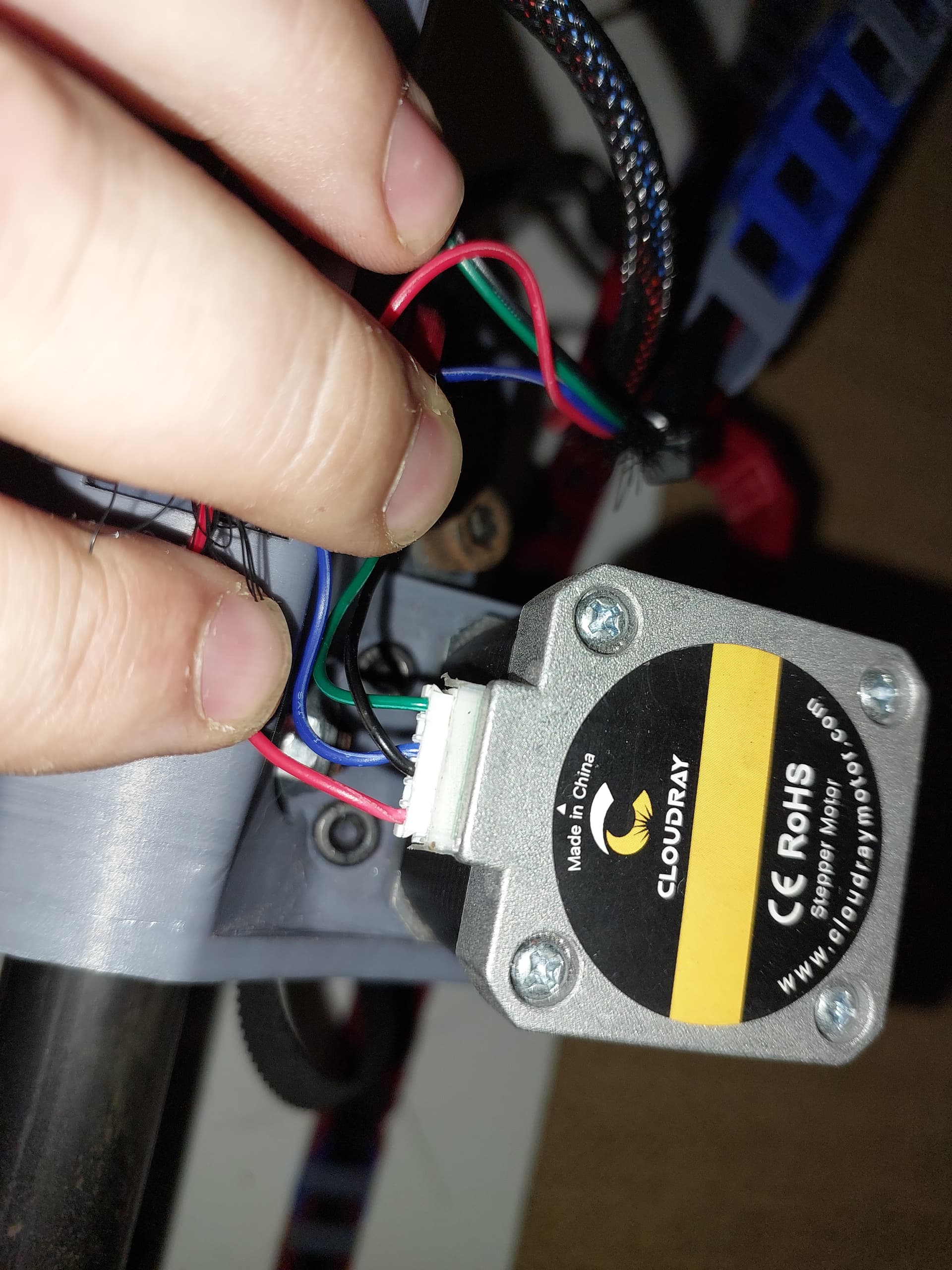
On the motors, the coils are pins 1/4 and 3/6 You can see this in your first couple of pictures. Red/blue are one pair and black/green are another pair.
Call the mobo pins 1, 2, 3, 4; Motor 1 as A1, A2, A3, A4, A5, A6; Motor B as B1, B2, B3, B4. B5, B6
Wire from 1 to A1
Wire from 2 to B4
Wire from 3 to A3
wire from 4 to B6
Wire from A4 to B1
wire from A6 to B3
This is for Z motors that need to turn the same way for both motors. The series wiring example in the V1 docs changes polarity on one coil so the motors turn opposite directions, which the Primo needs for the X/Y axes.