Jerry rig tug of war between the two steppers? First to skip steps loses. Don’t know if you can easily rig diff currents for different steppers from the same board. This feels like something CNC Kitchen would have an episode on.
More digging " A good rule of thumb is to use between 10 and 24 times the motor’s nameplate voltage for the system bus voltage" so #2 seems better again.
Could mod a LR3 to tug itself… #define Y_CURRENT / Y2_CURRENT appropriate for the steppers being tested, strap additional belt from YZ plate 1 to YZ plate 2, wrapping around existing Ymin left and Ymin right belt holder blocks, or EMT/pulleys or something?
I do have some looped belts so I could make a bracket and do a tug of war…I might do that. I would like to quantify the power though. I do love some numbers.
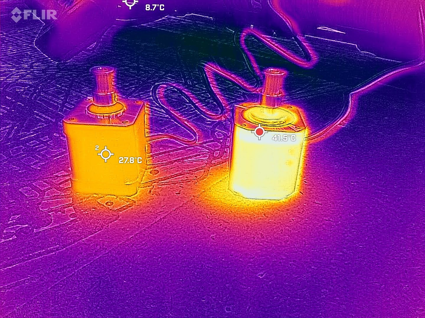
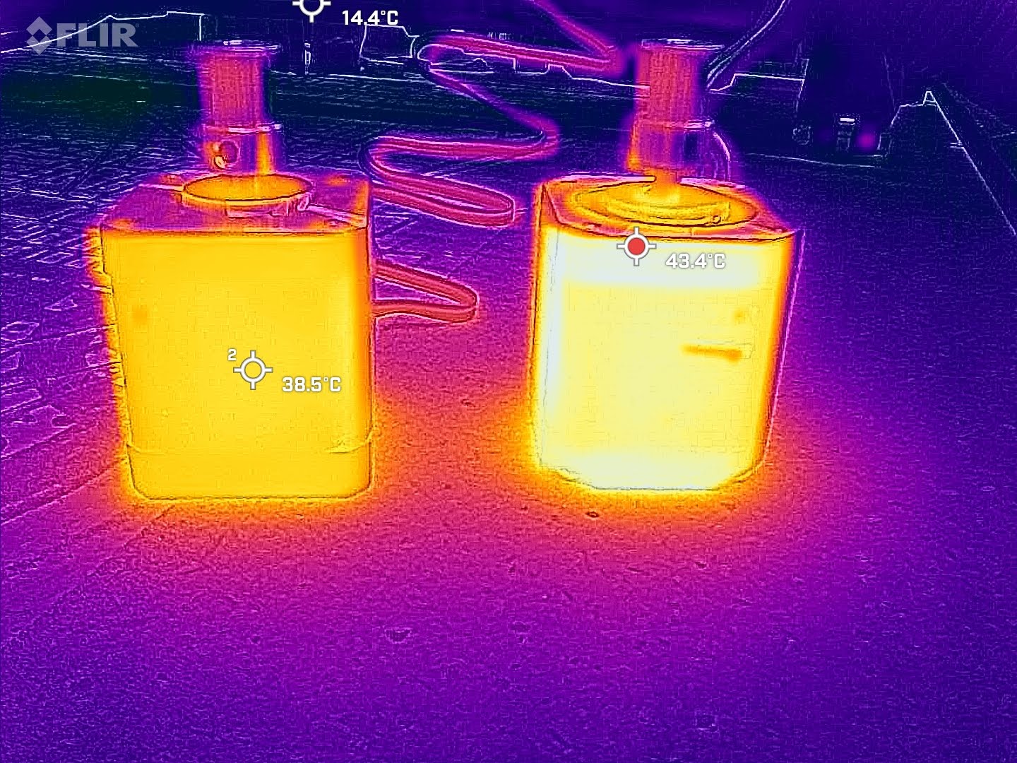
I have them both sitting powered up right now, same current. I will hit them with the thermal camera in 20 minutes or so when they warm up.
Okay I will have to test more in a bit after I get some orders out. So far at the same current settings #1 is hotter, and stronger. I can feel the heat, and I slapped a pulley on them and just grabbed it while moving them. Not scientific but I will figure out a better test later.
Current and torque (which be roughly proportional, more current = more torque, but not always exactly)
Inductance. Less is better. An inductive phase resists changes in current flow (thats what inductance is). This means it is slower to ramp up to its driven current, and slower to ramp back down. At faster speeds the driver has to apply higher voltages to get the current up quicker and then sink a lot of current when turning that phase off on the next step. This means they get hotter as well.
The voltage is simply a result of resistance per phase and maximum current. If you were driving them with a H bridge instead of a dedicated stepper driver IC, thats the maximum voltage you could use to ensure you dont go over the rated current.
When using a stepper driver IC you can run the 3v stepper on 12v/24v. The driver applies however much voltage is required for the current desired. When a phase is first switched on, the voltage over it will be 12v/24v, but the current will (for a very very short amount of time) be close to zero, and quickly ramp up (that is the inductance at play). The driver reduces voltage once it reaches the desired current. More inductance means its slower to ramp up. Higher voltage means you can get more current through it quicker (despite the inductance). Thats why a 24v 3d printer can move/accelerate faster than a 12v one (even if the stepper voltages are rated way less than either), because the inductance can be overcome better.
The ideal maximum voltage for a stepper can roughly be estimated by taking the square root of the inductance (in mH) and multiplying by 32. Any inductance higher than that or voltage lower than that will also work OK, but the closer the better (lowest inductance and highest voltage).
So I guess the 3.8mH would theoretically work best up around 60v, and the 4.8mH around 70v.
Inductance is only a concern when moving the motor. If its stationary, or only moves slowly, it doesn’t matter how much inductance there is.
If your going for a world speed record on a 3D printer your probably going to search to find the lowest inductance possible. For something like a CNC router, especially like the lowrider where your not really moving quickly, your probably not going to run into the speed limit where the inductance of the phases causes the peak current to drop off, reducing motor torque as you go faster and faster until you start losing steps. And if it did, you could switch from a 12v to a 24v supply and probably get a heap more speed/acceleration potential just from the increased voltage.